Deploy User-ID in a Large-Scale Network
User-ID Concepts in Large-Scale Networks
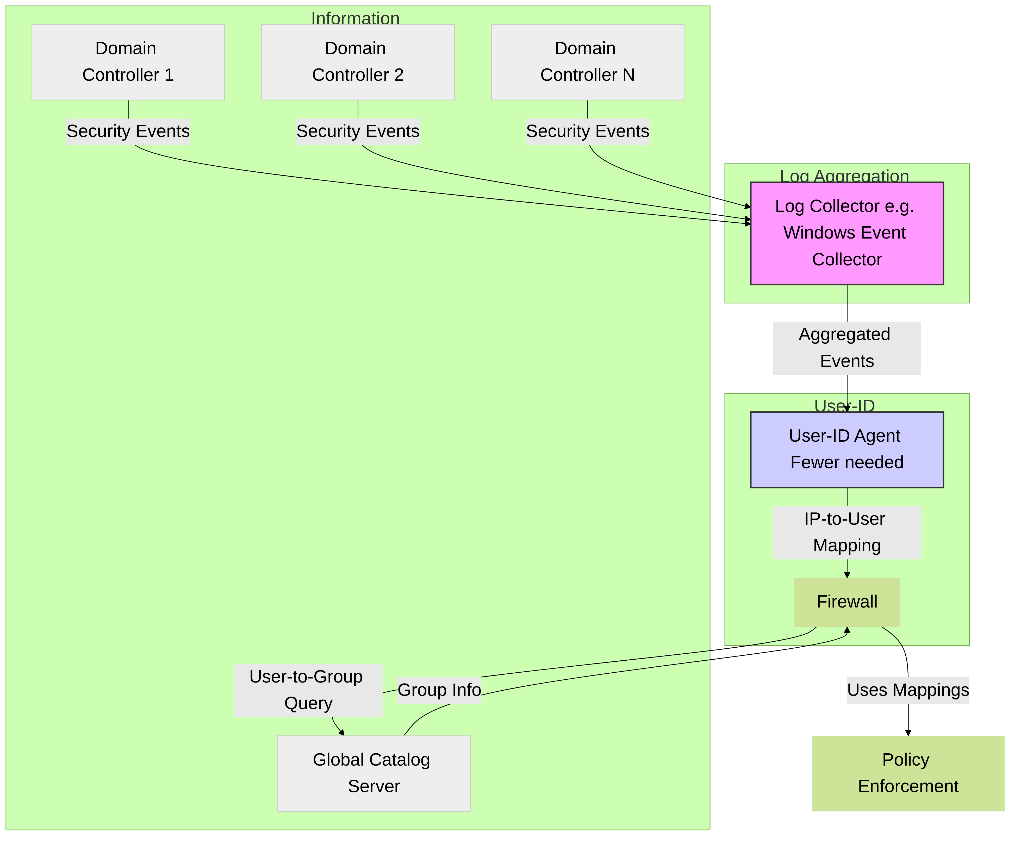
A large-scale network can have hundreds of information sources that firewalls query to map IP address - to - username mappings and to map username - to - group mappings. You can simplify User-ID administration for such a network by aggregating the user mapping and group mapping information before the User-ID agents collect it, thereby reducing the number of required agents.
Diagram 1: Information Aggregation (e.g., Log Forwarding)
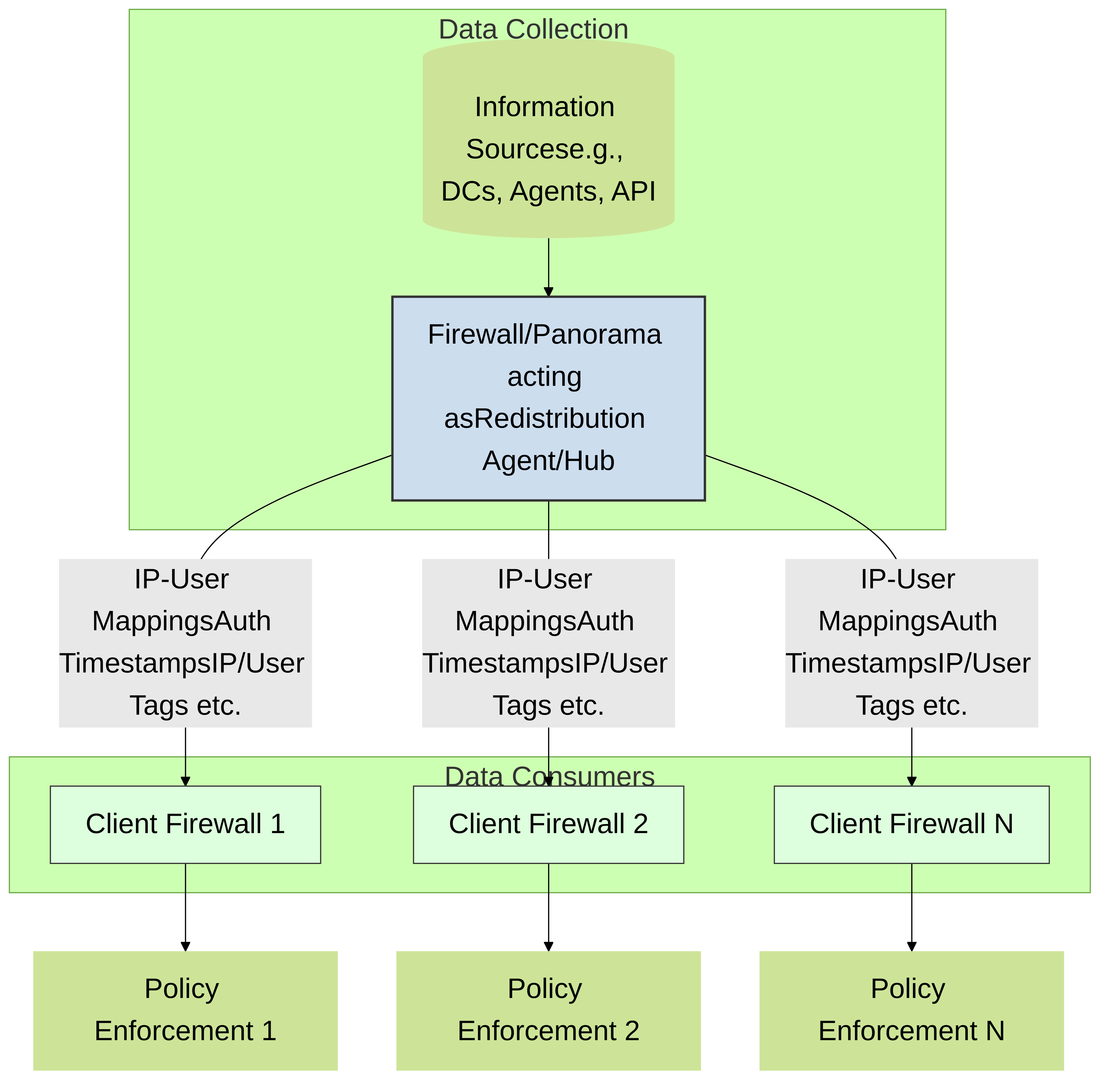
A large-scale network can also have numerous firewalls that use the mapping information to enforce policies. You can reduce the resources that the firewalls and information sources use in the querying process by configuring some firewalls to acquire mapping information through redistribution instead of direct querying. Redistribution also enables the firewalls to enforce user-based policies when users rely on local sources for authentication (such as regional directory services) but need access to remote services and applications (such as global data center applications).
If you Configure Authentication Policy, your firewalls also redistribute the Authentication Timestamps associated with user responses to authentication challenges. Firewalls use the timestamps to evaluate the timeouts for Authentication policy rules. The timeouts allow a user who successfully authenticates to later request services and applications without authenticating again within the timeout periods. Redistributing timestamps enables you to enforce consistent timeouts for each user even if the firewall that initially grants a user access is not the same firewall that later controls access for that user.
Diagram 2: Information Redistribution
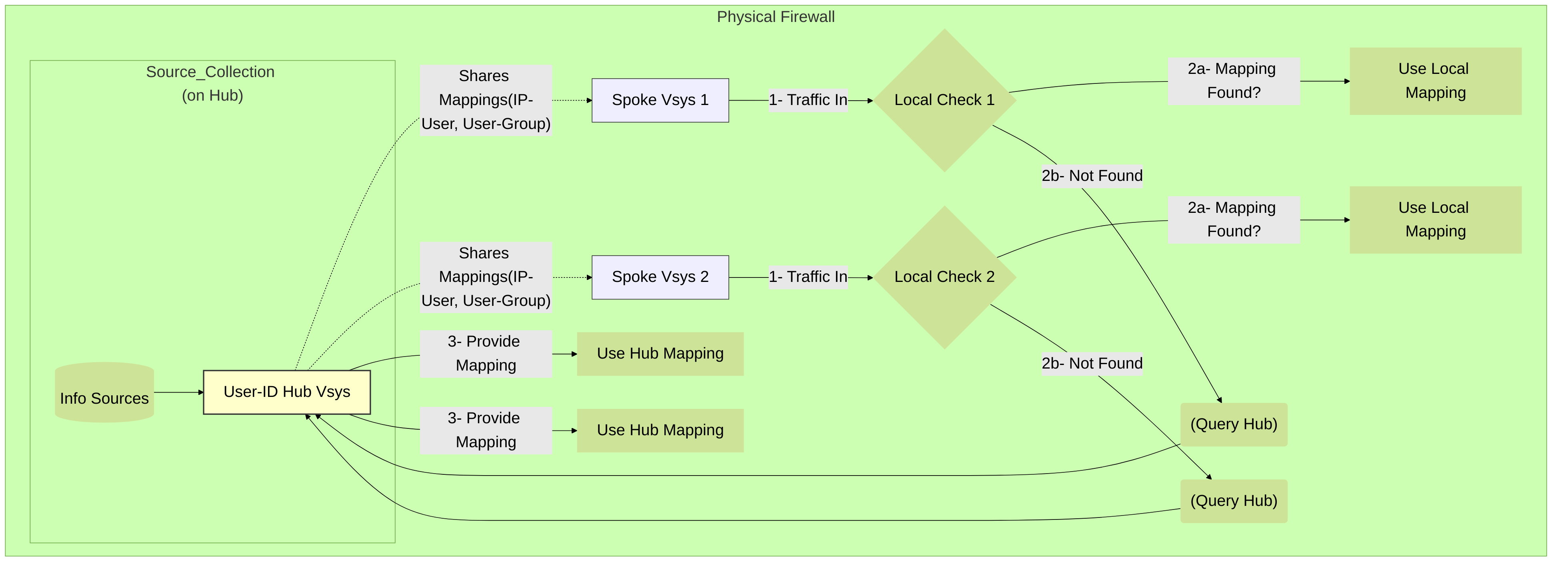
If you have configured multiple virtual systems on a single firewall, you can share IP address - to - username mapping information across virtual systems by selecting a virtual system as a User-ID hub .
Diagram 3: User-ID Hub (Intra-Firewall Virtual Systems)
Deploy User-ID for Numerous Mapping Information Sources
You can use Windows Log Forwarding and Global Catalog servers to simplify user mapping and group mapping in a large-scale network of Microsoft Active Directory (AD) domain controllers or Exchange servers. These methods simplify User-ID administration by aggregating the mapping information before the User-ID agents collect it, thereby reducing the number of required agents.
Windows Log Forwarding and Global Catalog Servers
Because each User-ID agent can monitor up to 100 servers, the firewall needs multiple User-ID agents to monitor a network with hundreds of AD domain controllers or Exchange servers. Creating and managing numerous User-ID agents involves considerable administrative overhead, especially in expanding networks where tracking new domain controllers is difficult. Windows Log Forwarding enables you to minimize the administrative overhead by reducing the number of servers to monitor and thereby reducing the number of User-ID agents to manage. When you configure Windows Log Forwarding, multiple domain controllers export their login events to a single domain member (the Windows Event Collector ) from which a User-ID agent collects the user mapping information.
You can configure Windows Log Forwarding for Windows Server versions 2012 and 2012 R2. Windows Log Forwarding is not available for non-Microsoft servers.
To collect group mapping information in a large-scale network, you can configure the firewall to query a Global Catalog server that receives account information from the domain controllers.
Information Flow Diagram
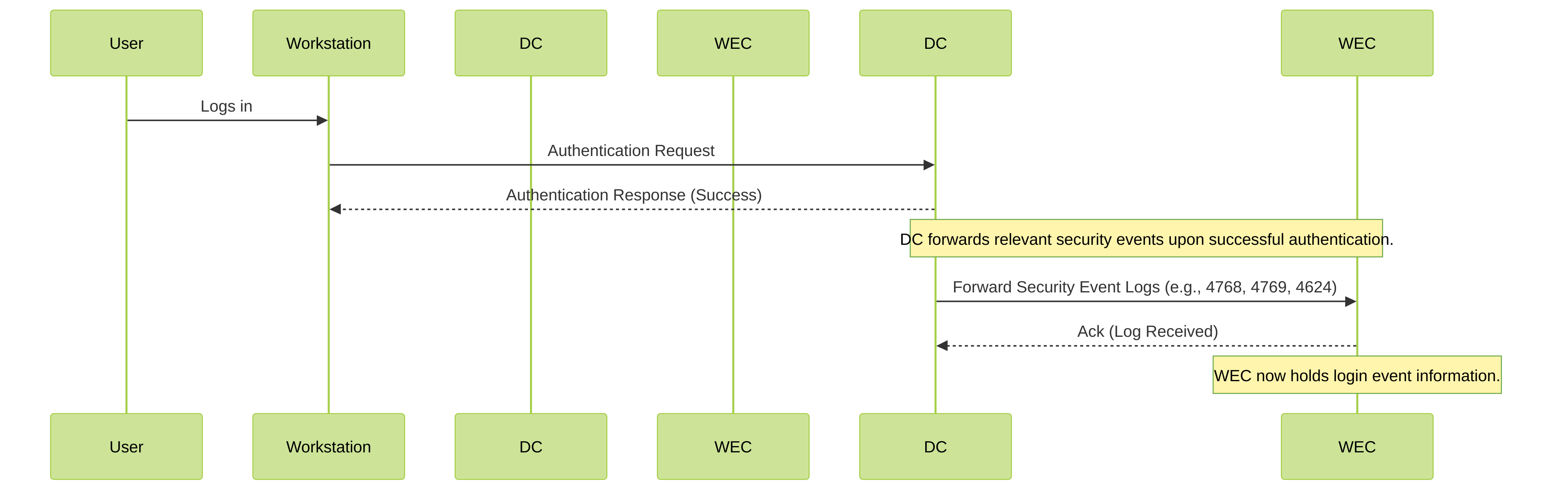
The above figure illustrates user mapping and group mapping for a large-scale network in which the firewall uses a Windows-based User-ID agent. See Plan a Large-Scale User-ID Deployment to determine if this deployment suits your network.
Knowledge Check
Question 1:
What is the primary benefit of using Windows Log Forwarding in a large-scale User-ID deployment?
Plan a Large-Scale User-ID Deployment
When deciding whether to use Windows Log Forwarding and Global Catalog servers for your User-ID implementation, consult your system administrator to determine:
- Bandwidth required for domain controllers to forward login events to member servers. The bandwidth is a multiple of the login rate (number of logins per minute) of the domain controllers and the byte size of each login event.
Domain controllers won't forward their entire security logs, they forward only the events that the user mapping process requires per login: four events for Windows Server 2012 and MS Exchange (Event IDs:
4768
,
4769
,
4770
,
4624
).
-
Whether the following network elements support the required bandwidth:
- Domain controllers support the processing load associated with forwarding the events.
- Member Servers support the processing load associated with receiving the events.
- Connections The geographic distribution (local or remote) of the domain controllers, member servers, and Global Catalog servers is a factor. Generally, a remote distribution supports less bandwidth.
Configure Windows Log Forwarding
To configure Windows Log Forwarding, you need administrative privileges for configuring group policies on Windows servers. Configure Windows Log Forwarding on all the Windows Event Collectors the member servers that collect login events from domain controllers. The following is an overview of the tasks; consult your Windows Server documentation for the specific steps.
-
On each Windows Event Collector, enable event collection, add the domain controllers as event sources, and configure the event collection query (subscription). The events you specify in the subscription vary by domain controller platform:
-
Windows Server 2012 (including R2) and 2016, or MS Exchange
The event IDs for the required events are
4768(Authentication Ticket Granted),4769(Service Ticket Granted),4770(Ticket Granted Renewed), and4624(Logon Success).
-
Windows Server 2012 (including R2) and 2016, or MS Exchange
The event IDs for the required events are
To forward events as quickly as possible, select Minimize Latency when configuring the subscription.
User-ID agents monitor the Security log on Windows Event Collectors, not the default Forwarded Events location . To change the event logging path to the Security log, perform the following steps on each Windows Event Collector.
- Open the Event Viewer.
- Right-click the Security log and select Properties .
-
Copy the
Log path
(default
%SystemRoot%\System32\Winevt\Logs\security.evtx) and click OK . - Right-click the Forwarded Events folder and select Properties .
-
Replace the default
Log path
(
%SystemRoot%\System32\Winevt\Logs\ForwardedEvents.evtx) by pasting the value from the Security log, and then click OK . - Configure a group policy to enable Windows Remote Management (WinRM) on the domain controllers.
- Configure a group policy to enable Windows Event Forwarding on the domain controllers.
Configuring Windows Log Forwarding
Configure User-ID for Numerous Mapping Information Sources
-
Configure Windows Log Forwarding on the member servers that will collect login events.
Configure Windows Log Forwarding. This step requires administrative privileges for configuring group policies on Windows servers.
-
Install the Windows-based User-ID agent.
Install the Windows-Based User-ID Agent on a Windows server that can access the member servers. Make sure the system that will host the User-ID agent is a member of the same domain as the servers it will monitor.
-
Configure the User-ID agent to collect user mapping information from the member servers (Windows Event Collectors).
- Start the Windows-based User-ID agent.
-
Select
User Identification > Discovery
and perform the following steps for each member server that will receive events from domain controllers:
- In the Servers section, click Add and enter a Name to identify the member server.
- In the Server Address field, enter the FQDN or IP address of the member server.
- For the Server Type , select Microsoft Active Directory .
- Click OK to save the server entry.
- Configure the remaining User-ID agent settings (refer to Configure the Windows-Based User-ID Agent for User Mapping).
- If the User-ID sources provide usernames in multiple formats, specify the format for the Primary Username when you Map Users to Groups.
The primary username is the username that identifies the user on the firewall and represents the user in reports and logs, regardless of the format that the User-ID source provides.
-
Configure an LDAP server profile to specify how the firewall connects to the
Global Catalog servers
(up to four) for group mapping information.
To improve availability, use at least two Global Catalog servers for redundancy.
You can collect group mapping information only for universal groups , not local domain groups (subdomains).
- Select Device > Server Profiles > LDAP , click Add , and enter a Name for the profile.
-
In the Servers section, for each Global Catalog, click
Add
and enter the server
Name
, IP address (
LDAP Server
), and
Port
. For a plaintext or Start Transport Layer Security (Start TLS) connection, use
Port
3268. For an LDAP over SSL connection, use Port3269. If the connection will use Start TLS or LDAP over SSL, select the Require SSL/TLS secured connection check box. -
In the
Base DN
field, enter the Distinguished Name (DN) of the point in the Global Catalog server where the firewall will start searching for group mapping information (for example,
DC=acbdomain,DC=com). - For the Type , select active-directory .
-
Configure an LDAP server profile to specify how the firewall connects to the servers (up to four) that contain
domain mapping
information.
User-ID uses this information to map DNS domain names to NetBIOS domain names. This mapping ensures consistent domain/username references in policy rules.
To improve availability, use at least two servers for redundancy.
The steps are the same as for the LDAP server profile you created for Global Catalogs in the previous step, except for the following fields:
- LDAP Server Enter the IP address of the domain controller that contains the domain mapping information.
-
Port
For a plaintext or Start TLS connection, use
Port
389. For an LDAP over SSL connection, use Port636. If the connection will use Start TLS or LDAP over SSL, select the Require SSL/TLS secured connection check box. -
Base DN
Select the DN of the point in the domain controller where the firewall will start searching for domain mapping information.
The value
- start with the string:
cn=partitions,cn=configuration(for example,cn=partitions,cn=configuration,DC=acbdomain,DC=com).
-
Create a group mapping configuration for each LDAP server profile you created.
- Select Device > User Identification > Group Mapping Settings .
- Click Add and enter a Name to identify the group mapping configuration.
- Select the LDAP Server Profile and ensure the Enabled check box is selected.
If the Global Catalog and domain mapping servers reference more groups than your security rules require, configure the Group Include List and/or Custom Group list to limit the groups for which User-ID performs mapping .
- Click OK and Commit .
Knowledge Check
Question 2:
When configuring an LDAP Server Profile on the firewall to query a Global Catalog for group mapping, which port should typically be used for an LDAP over SSL connection?
3268
is used for standard LDAP queries to the GC, while port
3269
is used for LDAP over SSL (LDAPS) queries to the GC. Ports
389
(LDAP) and
636
(LDAPS) are used for standard domain controller queries.
Insert Username in HTTP Headers
When you configure a secondary enforcement appliance with your Palo Alto Networks firewall to enforce user-based policy, the secondary appliance may not have the IP address - to - username mapping from the firewall. Transmitting user information to downstream appliances may require deployment of additional appliances such as proxies or negatively impact the user's experience (for example, users having to log in multiple times). By sharing the user's identity in the HTTP headers , you can enforce user-based policy without negatively impacting the user's experience or deploying additional infrastructure.
When you configure this feature, apply the URL Filtering profile to a Security policy rule, and commit your changes, the firewall:
- Populates the user and domain values with the format of the primary username in the group mapping for the source user.
- Encodes this information using Base64.
- Adds the Base64-encoded header to the payload.
- Routes the traffic to the downstream appliance.
If you want to include the username and domain only when the user accesses specific domains, configure a domain list and the firewall inserts the header only when a domain in the list matches the Host header of the HTTP request.
To share user information with downstream appliances, you - first enable User-ID and configure group mapping.
To include the username and domain in the header, the firewall requires the
IP address - to - username
mapping for the user. If the user isn't mapped, the firewall inserts
unknown
in Base64 encoding for both the domain and username in the header.
To include the username and domain in headers for HTTPS traffic, you - first create a Decryption profile to decrypt HTTPS traffic.
This feature supports forward-proxy decryption traffic.
-
Create or edit a URL Filtering profile.
The firewall does not insert headers if the action for the URL Filtering profile is block for the domain.
-
Create or edit an HTTP header insertion entry using predefined types.
You can define up to five headers for each profile.
- Select Dynamic Fields as the header Type .
- Add the Domains where you want insert headers. When the user accesses a domain in the list, the firewall inserts the specified header.
- Add a new Header or select X-Authenticated-User to edit it.
-
Select a header
Value
format (either
($domain)\($user)orWinNT://($domain)/($user)) or enter your own format using the($domain)and($user)dynamic tokens (for example,($user)@($domain)for UserPrincipalName).Do not use the same dynamic token (either
($user)or($domain)) more than once per value.Each value can be up to 512 characters. The firewall populates the
($user)and($domain)dynamic tokens using the primary username in the group mapping profile. For example:-
If the primary username is the sAMAccountName, the value for
($user)is the sAMAccountName and the value for($domain)is the NetBIOS domain name. -
If the primary username is the UserPrincipalName, the
($user)the user account name (prefix) and the($domain)is the Domain Name System (DNS) name.
-
If the primary username is the sAMAccountName, the value for
- ( Optional ) Select Log to enable logging for the header insertion.
- Apply the URL Filtering profile to the Security policy rule for HTTP or HTTPS traffic.
- Select OK twice to confirm the HTTP header configuration.
- Commit your changes.
-
Verify the firewall includes the username and domain in the HTTP headers.
-
Use the
show user user-ids allcommand to verify the group mapping is correct. -
Use the
show counter global name ctd_header_insertcommand to view the number of HTTP headers inserted by the firewall. -
If you configured logging in Step 7, check the logs for the inserted Base64 encoded payload (for example,
corpexample\testuserwould appear in the logs asY29ycGV4YW1wbGVcdGVzdHVzZXI=).
-
Use the
Redistribute Data and Authentication Timestamps
In a large-scale network, instead of configuring all your firewalls to directly query the mapping information sources, you can streamline resource usage by configuring some firewalls to collect mapping information through redistribution .
You can redistribute user mapping information collected through any method except Terminal Server (TS) agents . You cannot redistribute Group Mapping or HIP match information.
If you use Panorama to manage firewalls and aggregate firewall logs, you can use Panorama to manage User-ID redistribution. Leveraging Panorama is a simpler solution than creating extra connections between firewalls to redistribute User-ID information.
If you Configure Authentication Policy, your firewalls - also redistribute the Authentication Timestamps that are generated when users authenticate to access applications and services. Firewalls use the timestamps to evaluate the timeouts for Authentication policy rules. The timeouts allow a user who successfully authenticates to later request services and applications without authenticating again within the timeout periods. Redistributing timestamps enables you to enforce consistent timeouts across all the firewalls in your network.
Firewalls share data and authentication timestamps as part of the same redistribution flow ; you don't have to configure redistribution for each information type separately.
Firewall Deployment for Data Redistribution
In a large-scale network, instead of configuring all your firewalls to directly query the data sources, you can streamline resource usage by configuring some firewalls to collect data through redistribution. Data redistribution also provides granularity, allowing you to redistribute only the types of information you specify to only the devices you select. You can also filter the IP user mappings or IP address - to - tag mappings using subnets and ranges to ensure the firewalls collect only the mappings they need to enforce policy.
Data redistribution can be unidirectional (the agent provides data to the client) or bidirectional , where both the agent and the client can simultaneously send and receive data.
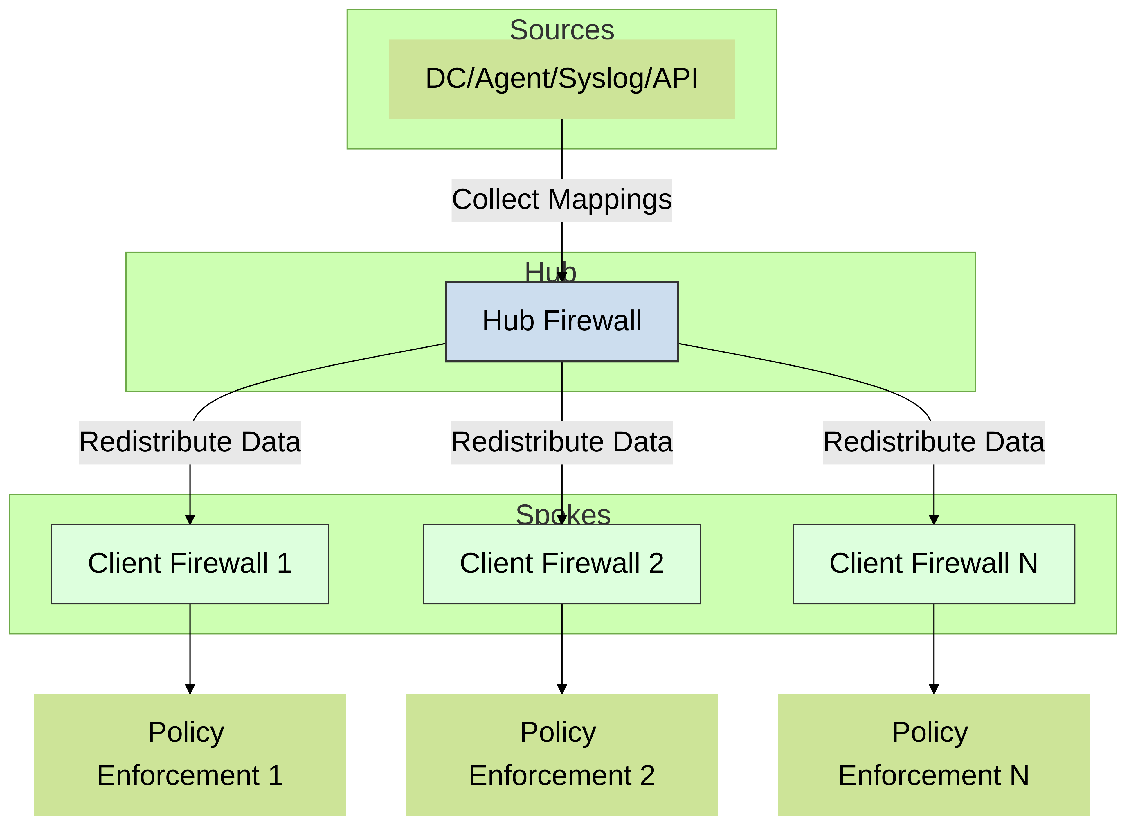
To redistribute the data, you can use the following architecture types:
-
Hub and spoke architecture for a single region:
To redistribute data between firewalls, use a hub and spoke architecture as a best practice . In this configuration, a hub firewall collects the data from sources such as Windows User-ID agents, Syslog Servers, Domain Controllers, or other firewalls. Configure the redistribution client firewalls to collect the data from the hub firewall.
For example, a hub (consisting of a pair of VM-50s for resiliency) could connect to the User-ID sources for the user mappings. The hub would then be able to redistribute the user mappings when the client firewalls that use the user mappings to enforce policy connect to the hub to receive data.
-
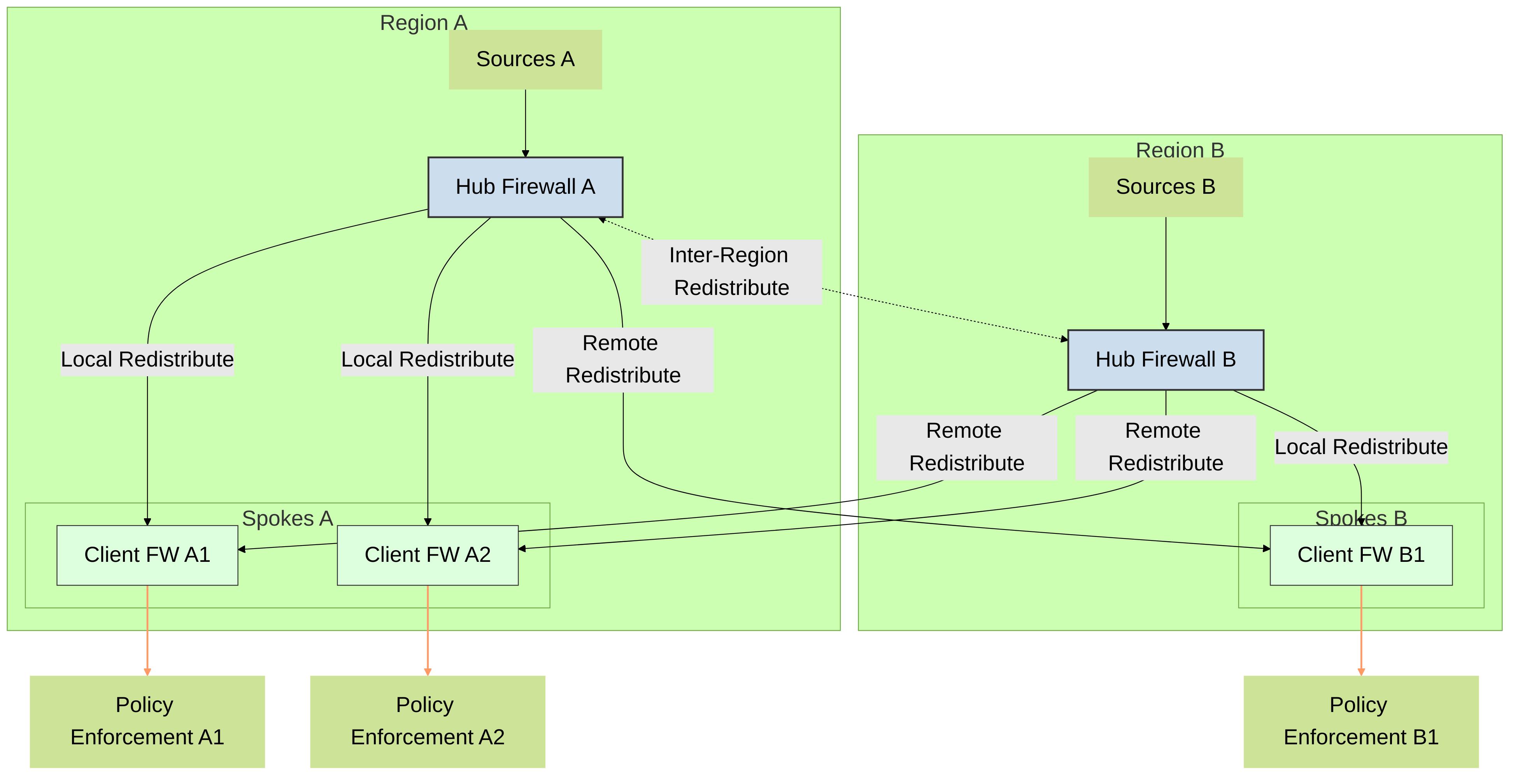
Multi-Hub and spoke architecture for multiple regions:
If you have firewalls deployed in multiple regions and want to distribute the data to the firewalls in all of these regions so that you can enforce policy consistently regardless of where the user logs in, you can use a multi-hub and spoke architecture for multiple regions.
Start by configuring a firewall in each region to collect data from the sources. This firewall acts as a local hub for redistribution. This firewall collects the data from all sources in that region so that it can redistribute it to the client firewalls. Next, configure the client firewalls to connect to the redistribution hubs for their region and all other regions so that the client firewalls have all data from all hubs.
As a best practice, enable bidirectional redistribution within a region if the firewalls need to both send and receive data. For example, if a firewall is acting as a GlobalProtect gateway for remote users and as a branch firewall for local users, the firewall - send the user mappings it collects for remote users to the hub firewall as well as receive the user mappings of the local users from the hub firewall.
-
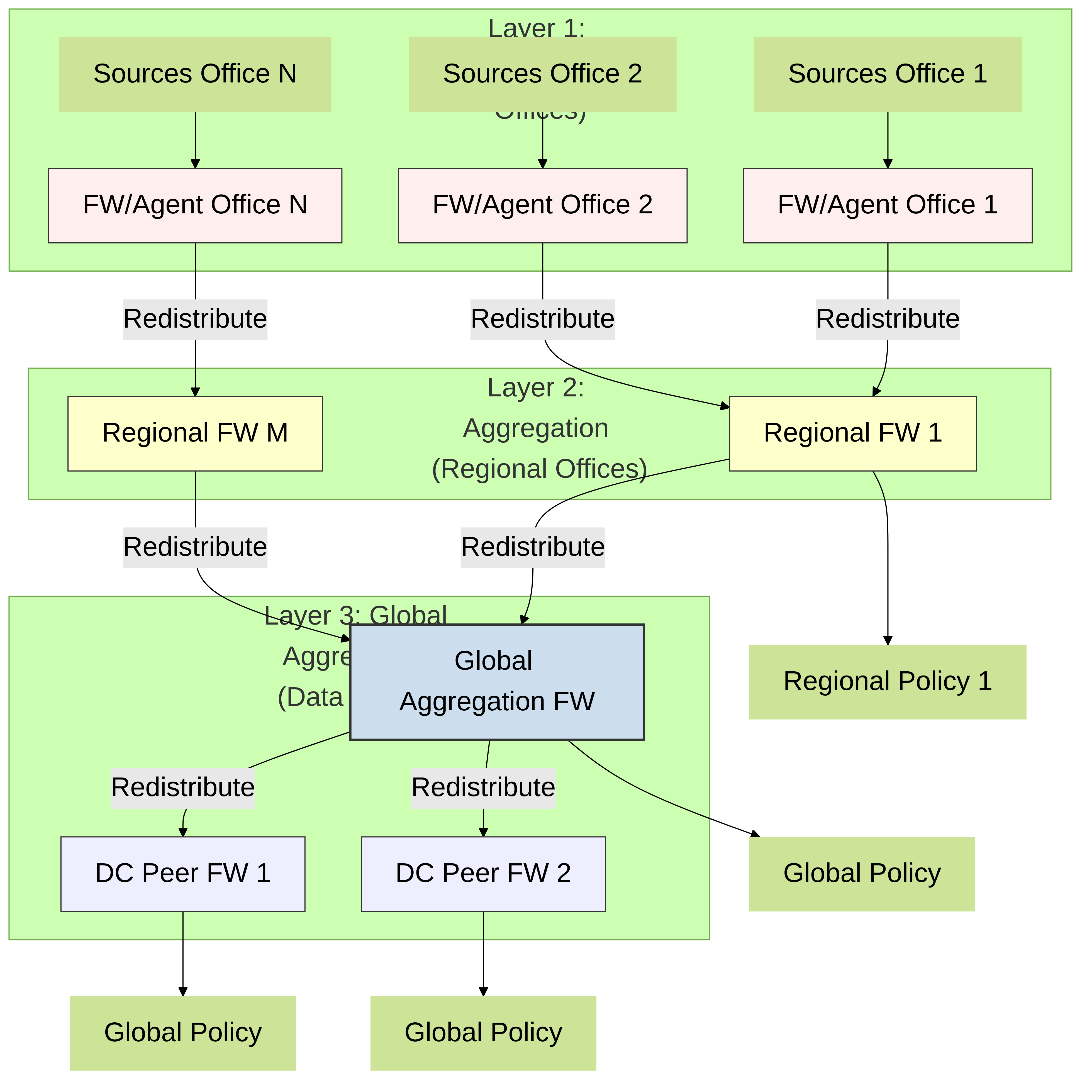
Hierarchical architecture:
To redistribute data, you can also use a hierarchical architecture. For example, to redistribute data such as User-ID information, organize the redistribution sequence in layers, where each layer has one or more firewalls. In the bottom layer, PAN-OS integrated User-ID agents running on firewalls and Windows-based User-ID agents running on Windows servers map IP addresses to usernames. Each higher layer has firewalls that receive the mapping information and authentication timestamps from up to 100 redistribution points in the layer beneath it. The top-layer firewalls aggregate the mappings and timestamps from all layers. This deployment provides the option to configure policies for all users in top-layer firewalls and region- or function-specific policies for a subset of users in the corresponding domains served by lower-layer firewalls.
In this scenario, three layers of firewalls redistribute mappings and timestamps from local offices to regional offices and then to a global data center. The data center firewall that aggregates all the information shares it with other data center firewalls so that they can all enforce policy and generate reports for users across your entire network. Only the bottom layer firewalls use User-ID agents to query the directory servers.
The information sources that the User-ID agents query do not count towards the maximum of ten hops in the sequence. However, Windows-based User-ID agents that forward mapping information to firewalls do count. Also in this example, the top layer has two hops: the first to aggregate information in one data center firewall and the second to share the information with other data center firewalls.
Redistribution Architecture Flowchart
Firewall Deployment Architectures for Data Redistribution
In a large-scale network, instead of configuring all your firewalls to directly query the data sources, you can streamline resource usage by configuring some firewalls to collect data through redistribution . Data redistribution also provides granularity, allowing you to redistribute only the types of information you specify to only the devices you select. You can also filter the IP user mappings or IP address - to - tag mappings using subnets and ranges to ensure the firewalls collect only the mappings they need to enforce policy.
Data redistribution can be unidirectional (the agent provides data to the client) or bidirectional , where both the agent and the client can simultaneously send and receive data.
To redistribute the data, you can use the following architecture types:
Hub and spoke architecture for a single region
To redistribute data between firewalls, use a hub and spoke architecture as a best practice . In this configuration, a hub firewall collects the data from sources such as Windows User-ID agents, Syslog Servers, Domain Controllers, or other firewalls. Configure the redistribution client firewalls (spokes) to collect the data from the hub firewall.
For example, a hub (consisting of a pair of VM-50s for resiliency) could connect to the User-ID sources for the user mappings. The hub would then be able to redistribute the user mappings when the client firewalls that use the user mappings to enforce policy connect to the hub to receive data.
Diagram: Hub and Spoke (Single Region)
Multi-Hub and spoke architecture for multiple regions
If you have firewalls deployed in multiple regions and want to distribute the data to the firewalls in all of these regions so that you can enforce policy consistently regardless of where the user logs in, you can use a multi-hub and spoke architecture for multiple regions.
Start by configuring a firewall in each region to collect data from the sources. This firewall acts as a local hub for redistribution. This firewall collects the data from all sources in that region so that it can redistribute it to the client firewalls. Next, configure the client firewalls to connect to the redistribution hubs for their region and all other regions so that the client firewalls have all data from all hubs.
As a best practice, enable bidirectional redistribution within a region if the firewalls need to both send and receive data. For example, if a firewall is acting as a GlobalProtect gateway for remote users and as a branch firewall for local users, the firewall must send the user mappings it collects for remote users to the hub firewall as well as receive the user mappings of the local users from the hub firewall.
Diagram: Multi-Hub and Spoke (Multiple Regions)
Hierarchical architecture
To redistribute data, you can also use a hierarchical architecture. For example, to redistribute data such as User-ID information, organize the redistribution sequence in layers , where each layer has one or more firewalls. In the bottom layer, PAN-OS integrated User-ID agents running on firewalls and Windows-based User-ID agents running on Windows servers map IP addresses to usernames. Each higher layer has firewalls that receive the mapping information and authentication timestamps from up to 100 redistribution points in the layer beneath it. The top-layer firewalls aggregate the mappings and timestamps from all layers. This deployment provides the option to configure policies for all users in top-layer firewalls and region- or function-specific policies for a subset of users in the corresponding domains served by lower-layer firewalls.
In this scenario, three layers of firewalls redistribute mappings and timestamps from local offices to regional offices and then to a global data center. The data center firewall that aggregates all the information shares it with other data center firewalls so that they can all enforce policy and generate reports for users across your entire network. Only the bottom layer firewalls use User-ID agents to query the directory servers.
The information sources that the User-ID agents query do not count towards the maximum of ten hops in the sequence. However, Windows-based User-ID agents that forward mapping information to firewalls do count. Also in this example, the top layer has two hops: the first to aggregate information in one data center firewall and the second to share the information with other data center firewalls.
Diagram: Hierarchical Architecture
Configure Data Redistribution
Before you configure data redistribution:
-
Plan the redistribution architecture. Some factors to consider are:
- Which firewalls will enforce policies for all data types and which firewalls will enforce region- or function-specific policies for a subset of data?
- How many hops does the redistribution sequence require to aggregate all data? The maximum allowed number of hops for user mappings is ten and the maximum allowed number of hops for IP address - to - username mappings and IP address - to - tag mappings is one.
- How can you minimize the number of firewalls that query the user mapping information sources? The fewer the number of querying firewalls, the lower the processing load is on both the firewalls and sources.
-
Configure the data sources from which your redistribution agents obtain the data to redistribute to their clients:
- user mappings from PAN-OS Integrated User-ID agents or Windows-based User-ID agents
- IP address - to - tag mappings for dynamic address groups
- username - to - tag mappings for dynamic user groups
- GlobalProtect for HIP-based Policy Enforcement
- data for device quarantine ( Panorama only )
- Configure Authentication Policy.
Data redistribution consists of:
- The redistribution agent that provides information
- The redistribution client that receives information
Perform the following steps on the firewalls in the data redistribution sequence.
-
On a redistribution client firewall, configure a firewall, Panorama, or Windows User-ID agent as a data redistribution agent.
- Select Device > Data Redistribution > Agents .
- Add a redistribution agent and enter a Name .
- Confirm that the agent is Enabled .
-
Add the agent using its
Serial Number
or its
Host and Port
.
- To add an agent using a serial number, select the Serial Number of the firewall you want to use as a redistribution agent.
-
To add an agent using its host and port information:
- Enter the information for the Host .
- Select whether the host is an LDAP Proxy .
-
Enter the
Port
(default is
5007, range is 1—65535). - ( Multiple virtual systems only ) Enter the Collector Name to identify which virtual system you want to use as a redistribution agent.
- ( Multiple virtual systems only ) Enter and confirm the Collector Pre-Shared Key for the virtual system you want to use as a redistribution agent.
-
Select one or more
Data Type
for the agent to redistribute.
- IP User Mappings IP address - to - username mappings for User-ID.
- IP Tags IP address - to - tag mappings for dynamic address groups.
- User Tags username - to - tag mappings for dynamic user groups.
- HIP Host information profile (HIP) data from GlobalProtect, which includes HIP objects and profiles.
- Quarantine List Devices that GlobalProtect identifies as quarantined.
-
(
Multiple virtual systems only
) Configure a virtual system as a collector that can redistribute data.
Skip this step if the firewall receives but does not redistribute data.
You can redistribute information among virtual systems on different firewalls or on the same firewall. In both cases, each virtual system counts as one hop in the redistribution sequence.
- Select Device > Data Redistribution > Collector Settings .
- Edit the Data Redistribution Agent Setup .
- Enter a Collector Name and Pre-Shared Key to identify this firewall or virtual system as a User-ID agent.
- Click OK to save your changes.
-
(
Optional but recommended
) Configure which networks you want to
include
in data redistribution and which networks you want to
exclude
from data redistribution.
You can include or exclude networks and subnetworks when redistributing either IP address - to - tag mappings or IP address - to - username mappings.
As a best practice, always specify which networks to include and exclude to ensure that the agent is only communicating with internal resources.
- Select Device > Data Redistribution > Include/Exclude Networks .
- Add an entry and enter a Name .
- Confirm that the entry is Enabled .
- Select whether you want to Include or Exclude the entry.
- Enter the Network Address for the entry.
- Click OK .
-
Configure the
service route
that the firewall uses to query other firewalls for User-ID information.
Skip this step if the firewall only receives user mapping information from Windows-based User-ID agents or directly from the information sources (such as directory servers) instead of from other firewalls.
- Select Device > Setup > Services .
- ( Firewalls with multiple virtual systems only ) Select Global (for a firewall-wide service route) or Virtual Systems (for a virtual system-specific service route), and then configure the service route.
- Click Service Route Configuration , select Customize , and select IPv4 or IPv6 based on your network protocols. Configure the service route for both protocols if your network uses both.
- Select UID Agent and then select the Source Interface and Source Address .
- Click OK twice to save the service route.
-
Enable the firewall to respond when other firewalls query it for data to redistribute.
Skip this step if the firewall receives but does not redistribute data.
Configure an Interface Management Profile with the User-ID service enabled and assign the profile to a firewall interface.
-
(
Optional but recommended
) Use a
custom certificate
from your enterprise PKI to establish a unique chain of trust from the redistribution client to the redistribution agent.
- On the redistribution client firewall, create a custom SSL certificate profile to use for outgoing connections.
- Select Device > Setup > Management > Secure Communication Settings .
- Edit the settings.
- Select the Customize Secure Server Communication option.
- Select the Certificate Profile you created in Substep 1.
- Click OK .
- Customize Communication for Data Redistribution .
- Commit your changes.
-
Enter the following CLI command to confirm the certificate profile (
SSL config)
uses
Custom certificates
:
show redistribution agent state(where
-
(
Optional but recommended
) Use a
custom certificate
from your enterprise PKI to establish a unique chain of trust from the redistribution agent to the redistribution client.
- On the redistribution agent firewall, create a custom SSL/TLS service profile for the firewall to use for incoming connections.
- Select Device > Setup > Management > Secure Communication Settings .
- Edit the settings.
- Select the Customize Secure Server Communication option.
- Select the SSL/TLS Service Profile you created in Step 1.
- Click OK .
- Commit your changes.
-
Enter the following CLI command to confirm the certificate profile (
SSL config)
uses
Custom certificates
:
show redistribution service status.
-
Verify the agents correctly redistribute data to the clients.
- View the agent statistics ( Device > Data Redistribution > Agents ) and select Status to view a summary of the activity for the redistribution agent, such as the number of mappings that the client firewall has received.
- Confirm that the Connected status is yes .
-
On the agent, access the CLI and enter the following CLI command to check the status of the redistribution:
show redistribution service status. -
On the agent, enter the following CLI command to view the redistribution clients:
show redistribution service client all. -
On the client, enter the following CLI command to check the status of the redistribution:
show redistribution service client all. - Confirm the Source Name in the User-ID logs ( Monitor > Logs > User-ID ) to verify that the firewall receives the mappings from the redistribution agents.
- On the client, view the IP-Tag log ( Monitor > Logs > IP-Tag ) to confirm that the client firewall receives data.
-
On the client, enter the following CLI command and verify that the source the firewall receives the mappings
From
is
REDIST
:
show user ip-user-mapping all.
-
(
Optional
) To troubleshoot data redistribution, enable the
traceroute option
.
When you enable the traceroute option, the firewall that receives the data appends its IP address to the
-
On the redistribution agent where the source originates, enter the following CLI command:
debug user-id test cp-login traceroute yes ip-address(whereuser -
On a client of the firewall where you configured the traceroute, verify the firewall redistributes the data by entering the following CLI command:
show user ip-user-mapping all.
The firewall displays the timestamp for the creation of the mapping ( SeqNumber ) and whether the user has GlobalProtect ( GP User ).
admin > show user ip-user-mapping-mp ip 192.0.2.0

IP address:       192.0.2.0 (vsys1)
User:             jimdoe
From:             REDIST
Timeout:          889s
Created:          11s ago
Origin:           198.51.100.0
SeqNumber:        15895329682-67831262
GP User:          No
Local HIP:        No
Route Node 0:     198.51.100.0 (vsys1)
Route Node 1:     198.51.100.1 (vsys1)
-
On the redistribution agent where the source originates, enter the following CLI command:
Knowledge Check
Question 3:
Which type of User-ID information CANNOT be redistributed between firewalls?
Share User-ID Mappings Across Virtual Systems
To simplify User-ID™ source configuration when you have multiple virtual systems, configure the User-ID sources on a single virtual system to share IP address - to - username mappings and username - to - group mappings with all other virtual systems on the firewall.
Configuring a single virtual system as a User-ID hub simplifies user mapping by eliminating the need to configure the sources on multiple virtual systems, especially if traffic will pass through multiple virtual systems based on the resources the user is trying to access (for example, in an academic networking environment where a student will be accessing different departments whose traffic is managed by different virtual systems).
To map the user or group, the firewall uses the mapping table on the local virtual system and applies the policy for that user or group. If the firewall does not find the mapping for a user or group on the virtual system where that user's traffic originated, the firewall queries the hub to fetch the IP address - to - username information for that user or group mapping information for that group. If the firewall locates the mapping on both the User-ID hub and the local virtual system, the firewall uses the mapping it learns locally. If the mapping on the local firewall differs from the mapping on the virtual system hub, the firewall uses the local mapping.
After you configure the User-ID hub, the virtual system can use the mapping table on the User-ID hub when it needs to identify a user for user-based policy enforcement or to display the username in a log or report but the source is not available locally. When you select a hub, the firewall retains the mappings on other virtual systems so we recommend consolidating the User-ID sources on the hub. However, if you don't want to share mappings from a specific source, you can configure an individual virtual system to perform user or group mapping.
-
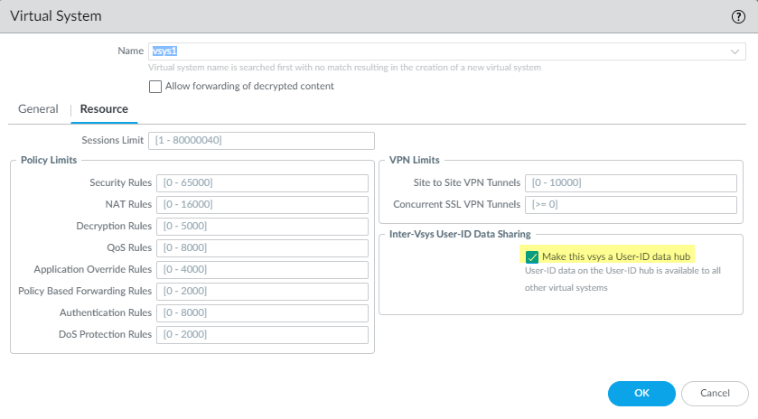
Assign the virtual system as a User-ID hub.
- Select Device > Virtual Systems and then select the virtual system where you consolidated your User-ID sources.
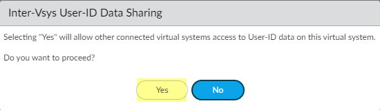
- On the Resource tab, check Make this vsys a User-ID data hub and click Yes to confirm. Then click OK .
-
Click
Yes
to confirm.
-
Select the
Mapping Type
that you want to share then click
OK
.
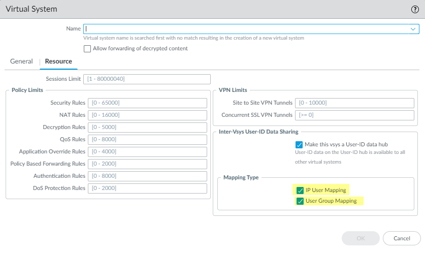
- IP User Mapping Share IP address - to - username mapping information with other virtual systems.
- User Group Mapping Share group mapping information with other virtual systems.
You - select at least one mapping type.
-
Consolidate your User-ID sources and migrate them to the virtual system that you want to use as a User-ID hub.
This consolidates the User-ID configuration for operational simplicity. By configuring the hub to monitor servers and connect to agents that were previously monitored by other virtual systems, the hub collects the user mapping information instead of having each virtual system collect it independently. If you don't want to share mappings from specific virtual systems, configure those mappings on a virtual system that will not be used as the hub.
Use the same format for the Primary Username across virtual systems and firewalls.
- Remove any sources that are unnecessary or outdated.
- Identify all configurations for your Windows-based or integrated agents and any sources that send user mappings using the XML API and copy them to the virtual system you want to use as a User-ID hub.
On the hub, you can configure any User-ID source that is currently configured on a virtual system. However, IP address-and-port-to-username mapping information from Terminal Server agents are not shared between the User-ID hub and the connected virtual systems.
- Specify the subnetworks that User-ID should include in or exclude from mapping.
- Define the Ignore User List .
- On all other virtual systems, remove any sources that are on the User-ID hub.
- Commit the changes to enable the User-ID hub and begin collecting mappings for the consolidated sources.
-
Confirm the User-ID hub is mapping the users and groups.
-
Use the
show user ip-user-mapping allcommand to show the IP address - to - username mappings and which virtual system provides the mappings. -
Use the
show user user-id-agent statisticscommand to show which virtual system is serving as the User-ID hub. - Confirm the hub is sharing the group mappings by using the following CLI commands:
-
show user group-mapping statistics -
show user group-mapping state all -
show user group list -
show user group name
-
Use the
Knowledge Check
Question 4:
If a firewall has multiple virtual systems and one is configured as a User-ID Hub, what happens if a specific user mapping exists both locally on a spoke vsys and on the hub vsys?