IoT Security Overview
You have several options when a license for an IoT Security subscription or a third-party integration add-on expires. If you no longer want a firewall to subscribe to IoT Security services or integrate with third-party systems, you can let the license expire. If you do want to continue using these services or integrations, you can extend trial and eval licenses, renew paid licenses, and even convert licenses from one type to another.
License Extensions
Before buying IoT Security, you might first try it out and evaluate it. The initial term of a trial or eval (evaluation) license is 60 days and can be extended in 30-day increments. To extend the trial or eval term, request a 30-day extension through your Palo Alto Networks sales representative or sales engineer.
License Renewals
As a paid license approaches its expiration date, you can renew it so that there’s no break in service, the next license beginning immediately after the current license ends. You can renew the following licenses:
- IoT Security Subscription lab license
- IoT Security Subscription prod (production) license
- IoT Security, Doesn’t Require Data Lake (DRDL) Subscription lab license
- IoT Security, DRDL Subscription prod license
- Basic IoT Security Third-party Integrations Add-on license
- Advanced IoT Security Third-party Integrations Add-on license
To renew any of these licenses, contact your Palo Alto Networks sales representative.
License Conversions
A license conversion is the change of one license type to another. The license can be for an IoT Security subscription or a third-party integration add-on.
You can convert an IoT Security license on a firewall from trial to prod, but not from eval to prod. An eval license is for an eval firewall, which is Palo Alto Networks property and loaned out for temporary use. However, if you create an IoT Security tenant URL for eval licenses on eval firewalls and then replace them with prod licenses on prod firewalls, you can continue using the same IoT Security tenant URL.
Palo Alto Networks supports the following conversions:
IoT Security license conversions
- Trial > Prod
- IoT Security Subscription > IoT Security, Doesn't Require Data Lake (DRDL) Subscription
- IoT Security, DRDL Subscription > IoT Security Subscription
Activate a Strata Logging Service instance before converting from a subscription that doesn't require a data lake to one that does.
IoT Security Third-party Integrations Add-on license conversions
- Basic > Advanced
- Advanced > Basic
All conversions can be done after the current license expires at the end of its term, but only conversions considered to be upgrades are allowed midterm. Midterm conversions take place immediately, replacing the previous term with the new term. The following conversions are considered to be upgrades:
IoT Security license upgrades
- Trial version of any type of license > Prod version of any type of license
- IoT Security Subscription > IoT Security, DRDL Subscription
IoT Security Third-party Integrations Add-on license upgrades
- Trial version of any type of add-on > Prod version of any type of add-on
- Basic > Advanced
Converting IoT Security licenses from trial to prod generates a new purchase order with a link to a new onboarding workflow. During the onboarding process, you can select the existing IoT Security tenant you were previously using for trial purposes. The rest of the onboarding workflow follows the same mechanism for activating prod licenses on firewalls as it did for activating trial licenses.
To convert any licenses, contact your Palo Alto Networks sales representative.
IoT Security Prerequisites
Ensure your environment meets all prerequisites for deploying IoT Security with Palo Alto Networks next-generation firewalls:
-
One or more firewalls running
PAN-OS 8.1 to PAN-OS 9.0.2 with Panorama management, or PAN-OS 9.0.3 or later with or without Panorama management.
Note: Check the specific PAN-OS version for desired functionality (visibility vs. automatic policy enforcement).
Firewalls running PAN-OS 8.1, PAN-OS 9.0, and PAN-OS 9.1 support IoT Security for device visibility and manual policy enforcement. Firewalls running PAN-OS 10.0 or later support IoT Security for both device visibility and automatic policy enforcement through Device-ID .
-
One IoT Security license PER FIREWALL that integrates with IoT Security.
Note: Not all firewalls on your network need a license, only those sending logs or receiving policy/mapping updates.
The license controls whether IoT Security ingests log data... and whether a firewall can pull IP address-to-device mappings and policy rule recommendations... for use in its security policy rules.
(A note about IP address-to-device mappings: IoT Security uses patented multi-tier machine-learning algorithms to profile device behaviors and identify the device type, make, model, OS, and OS version. It bundles this set of attributes into a logical object, maps it to the IP address of a device, and sends it to the firewall. This object is called an IP address-to-device mapping.)
When you buy an IoT Security subscription, you have a 90-day grace period to activate the license on a firewall. If you activate it within the first 90 days, the subscription starts on the activation date. Otherwise, it starts 90 days after the purchase date.
A Panorama management server itself does NOT require an IoT Security license.
-
When using
IoT Security Subscription
, which stores data in Strata Logging Service,
you need one Strata Logging Service license PER ACCOUNT.
(When using
IoT Security, Doesn't Require Data Lake Subscription
, you do not need a Strata Logging Service license.)
Be Aware: Firewalls stream logs automatically and continuously to the IoT Security infrastructure regardless of whether a data lake subscription is used for storage. Data retention periods vary by data type.
Tip: Use the Cortex sizing calculator for new SLS instances to estimate storage needs based on the number of firewalls with IoT Security licenses.
Your Strata Logging Service subscription can either be new or an existing one, and the data lake can be in the Americas, European Union, or Asia-Pacific region. Regardless of the use of the data lake, firewalls stream logging data automatically and continuously to the IoT Security infrastructure where it is retained for varying periods of time based on data type. For details about data retention, see IoT/OT Security Privacy documentation.
For a new Strata Logging Service instance, figure out the amount of storage you'll need with the Cortex sizing calculator. When making your calculations, enter the number of firewalls with an IoT Security license and select IoT Security.
-
Using the logging service (for either subscription type) requires a Premium Support license or better.
Note: A Premium Support license is automatically included with the purchase of a Strata Logging Service instance.
- A Threat Prevention license is REQUIRED for IoT Security to get all the traffic and threat logs necessary to fully assess risk and detect vulnerabilities.
-
The following licenses and firewall capability provide additional value (RECOMMENDED, but not strictly required for basic function):
- A DNS Security license helps IoT Security detect DNS-related threats and risks.
- A Wildfire license enhances the detection of malware and file-related vulnerabilities.
- A URL Filtering license controls the online content devices can access and how they can interact with it.
- Enabling SSL decryption on the firewall SIGNIFICANTLY improves the coverage and accuracy of device identification, as well as helping with risk assessment and threat detections.
- When using IoT Security on networks with medical equipment, make sure the application content version on your firewalls is 8367-6513 or later . These versions include healthcare-specific applications needed for medical equipment discovery and utilization data.
- When integrating IoT Security with Prisma Access, Prisma Access must be running the Prisma Access 2.0-Innovation release or later WITH an IoT Security add-on. Additional requirements apply (see IoT Security Integration with Prisma Access documentation).
- When Panorama manages firewalls running PAN-OS 10.2, it requires the 3.1 cloud services plugin.
IoT Security Solution Components
IoT Security is an on-demand cloud subscription service designed to discover and protect the growing number of connected “things” on your network. Unlike IT devices such as laptop computers that perform a wide variety of tasks, IoT devices tend to be purpose-built with a narrowly defined set of functions. As a result, IoT devices generate unique, identifiable patterns of network behavior. Using machine learning and AI, IoT Security recognizes these behaviors and identifies every device on the network, creating a rich, context-aware inventory that’s dynamically maintained and always up to date.
After IoT Security identifies a device and establishes a baseline of its normal network activities, it continues monitoring its network activity so it can detect any unusual behavior indicative of an attack or breach. If it detects such behavior, IoT Security notifies administrators through security alerts in the portal and, depending on each administrator’s notification settings, through email and SMS notifications.
IoT Security also uses those behaviors and device identities to automatically generate security policy rule recommendations that allow IoT devices to continue doing normal network activities and block them from doing anything unusual. Panorama or next-generation firewalls can then import these policy rules and enforce them.
For Panorama-managed firewalls that have an IoT Security subscription requiring Strata Logging Service – Panorama can only import policy rule recommendations if it was used to onboard its managed firewalls to Strata Logging Service.
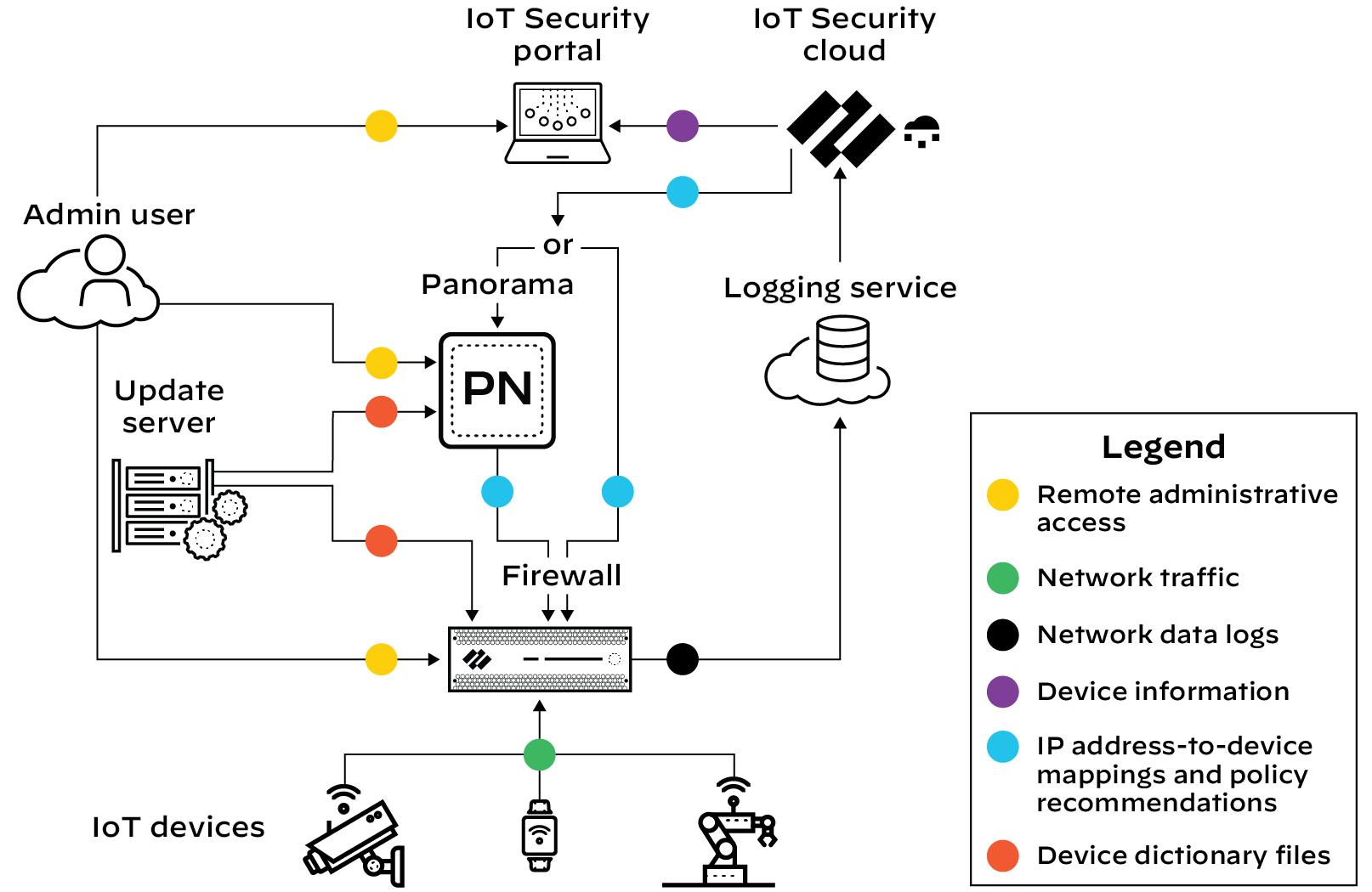
Figure: Basic IoT Security Solution Architecture showing data flow from firewalls to logging service to IoT Security.
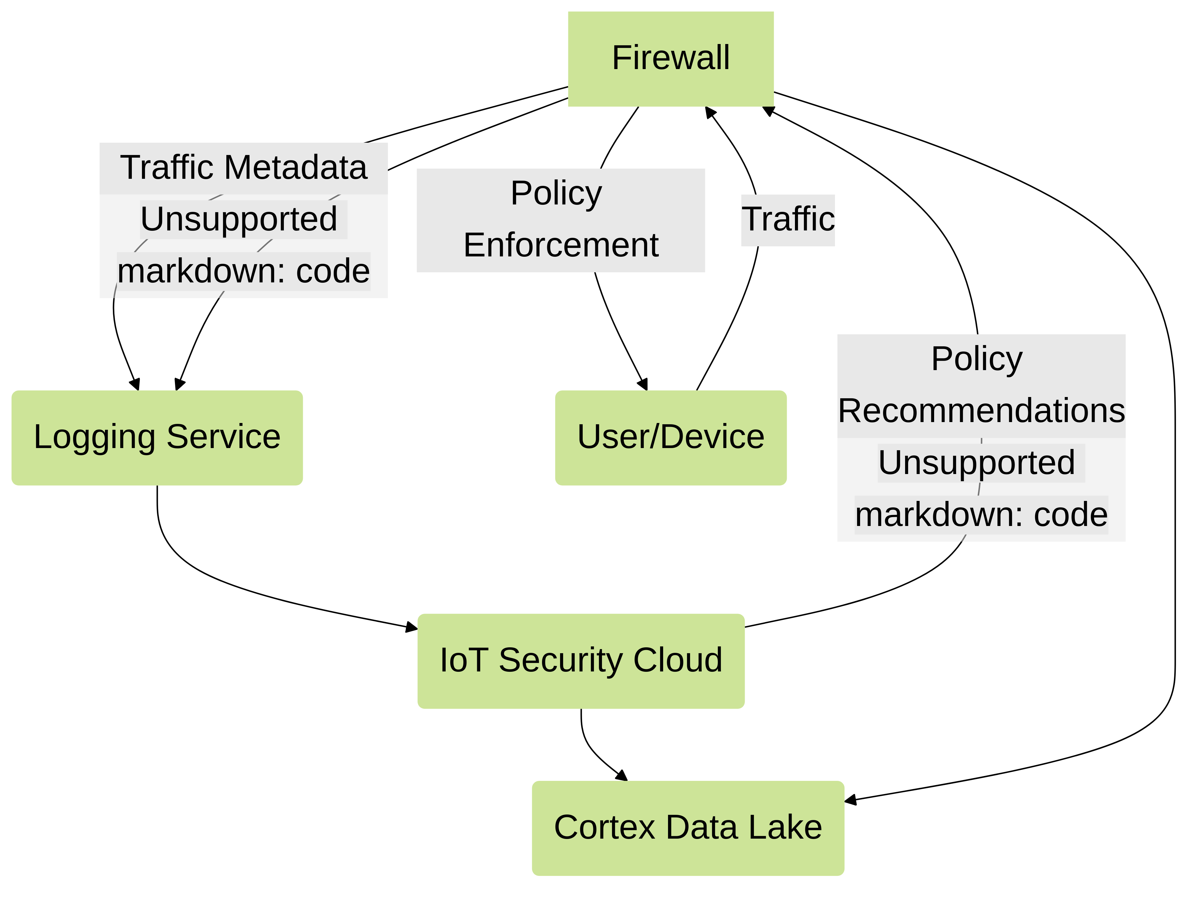
The firewall collects metadata from the network traffic of IoT devices, generates Enhanced Application logs (EALs), and forwards them to the logging service. The IoT Security cloud then extracts metadata from these logs for analysis and employs AI and machine-learning algorithms to detect and identify IoT devices using its patented three-tier deep-learning engine:
- Tier 1: Device category —IoT Security first identifies the category to which an IoT device belongs. For example, it might identify network behaviors common to all security cameras.
- Tier 2: Device profile —IoT Security next constructs a profile of the device, learning its vendor, make, and model. For example, it might discover that the camera behaves in ways that uniquely identify it, such as checking a particular server for software updates for example.
- Tier 3: Device instance —IoT Security continues its analysis until it discerns behaviors unique to a specific instance of the identified security camera.
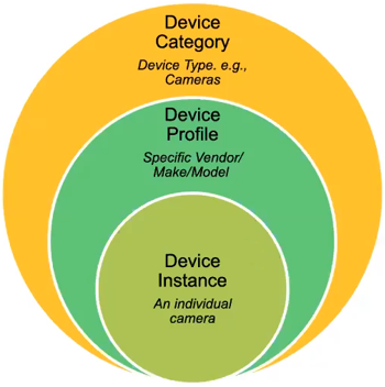
Figure: The three tiers of the IoT Security deep-learning engine for device identification.
IoT Security looks at over 200 parameters in network traffic metadata , including DHCP option 55 parameter lists, HTTP user agent IDs, protocols, protocol headers, and a host of others. It matches the network traffic patterns of new devices with those of previously identified devices to identify the same types or similar types of devices, even those it is encountering for the first time.
Depending on various factors such as how much network traffic IoT devices generate and how varied their behavior patterns are, IoT Security typically identifies most IoT devices with a high level of confidence during the first day it starts accessing metadata from the logging service. After that, IoT Security continues to increase the number of confidently identified devices until it identifies all or nearly all of them. During this time, you can log in to the IoT Security portal to check that the device inventory is being populated and monitor its progress.
A confidence score indicates the level of confidence IoT Security has in its identification of a device. IoT Security has three confidence levels based on calculated confidence scores: high (90-100%) , medium (70-89%) , and low (0-69%) .
In addition to using machine learning (ML) to observe network traffic and extract various attributes to identify devices and detect anomalous behaviors, IoT Security employs an ML-based model to check for SQL content injected into HTTP URLs, a technique commonly used in SQL vulnerability exploits. By using an ML-based model instead of a model based on rules, IoT Security can find certain patterns of injected SQL content even without specific signatures.
The architectural components that constitute the IoT Security solution are introduced here. Learn about the various components, how they work together, and how to set them up. Also learn about all the educational resources available for IoT Security.
IoT Security Solution Structure
Using AI and machine learning, IoT Security automatically discovers and identifies all network-connected devices and constructs a data-rich, dynamically updating inventory. In addition to identifying IoT devices and IT devices (laptops and servers for example), IoT Security provides deep visibility into network behaviors, establishing what’s normal and discerning what’s suspicious. When it detects a device vulnerability or anomalous behavior posing a threat, IoT Security notifies administrators, who can then take action to investigate and remediate the issue.
To accomplish all this, the cloud-based IoT Security app works with Palo Alto Networks next-generation firewalls, logging service, and update server, and optionally with Panorama and integrated third-party products. These elements of the IoT Security solution collaborate to carry out the following tasks:
- Firewalls with IoT Security subscriptions collect information about network traffic and forward their logs to the logging service, which streams metadata to IoT Security for analysis.
- The update server provides firewalls and Panorama with a regularly updated device dictionary file of device attributes (profile, vendor, category, and so on) that Security policy rules use for device identification, or Device-ID .
- IoT Security recommends Security policy rules based on Device-ID to firewalls. When Panorama provides centralized firewall management, IoT Security works through it to recommend Security policy rules to managed firewalls. When Panorama is not in use, IoT Security interacts directly with firewalls.
- IoT Security maps IP addresses to devices and notifies firewalls of their corresponding device attributes so they can enforce Device-ID-based Security policy rules that reference attributes in IP address-to-device mappings.
With a third-party integrations add-on license for your IoT Security account, you are able to expand IoT Security capabilities to include product-specific features and those of the integrated products to include IoT.
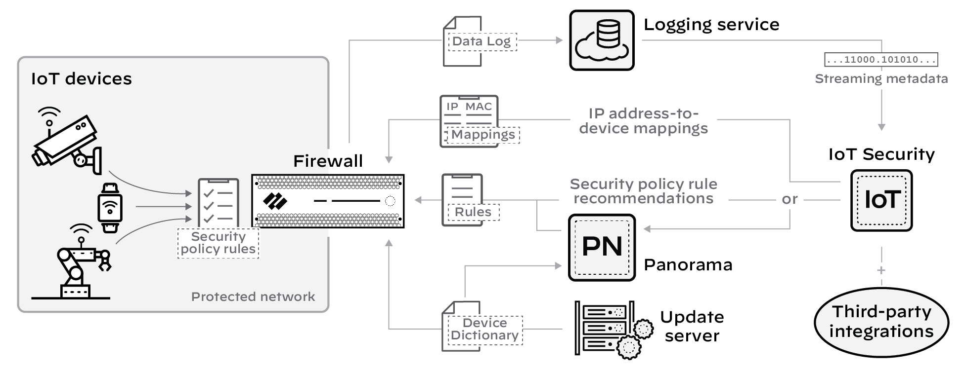
Figure: How firewalls interact with cloud services like IoT Security, Logging Service, and Update Server.
Learn about the major components that constitute the IoT Security solution:
- Device Data Collection
- Data Analysis
- IoT Device Protection
- Third-party Integrations
- Using Prisma Access instead of Next-generation Firewalls
1 - Device Data Collection
For IoT Security to identify IoT devices and establish a baseline of their acceptable network behaviors, it needs to analyze their network activity. That’s where next-generation firewalls come in. They log network traffic to which they apply Security policy rules and then forward logs to the logging service where IoT Security accesses them. Depending on whether your IoT Security subscription includes data storage, the logging service either streams metadata to your IoT Security account and Strata Logging Service instance or just to your IoT Security account.
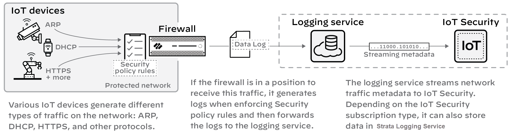
Figure: Data collection flow from firewall logs to the Logging Service and IoT Security.
Detailed Instructions: Onboard IoT Security, Prepare Your Firewall for IoT Security documentation.
2 - Data Analysis
IoT Security uses AI and machine-learning algorithms to analyze numerous aspects of the network behavior of a device and classify it within three levels or tiers... (Content similar to the overview section, focused on the *analysis* process). In addition to device identification, IoT Security applies proprietary and supplemental machine-learning technologies to threat detection. It automatically detects device vulnerabilities and notifies IoT Security administrators. It also detects anomalous network behavior indicative of attack or reconnaissance and generates security alerts.
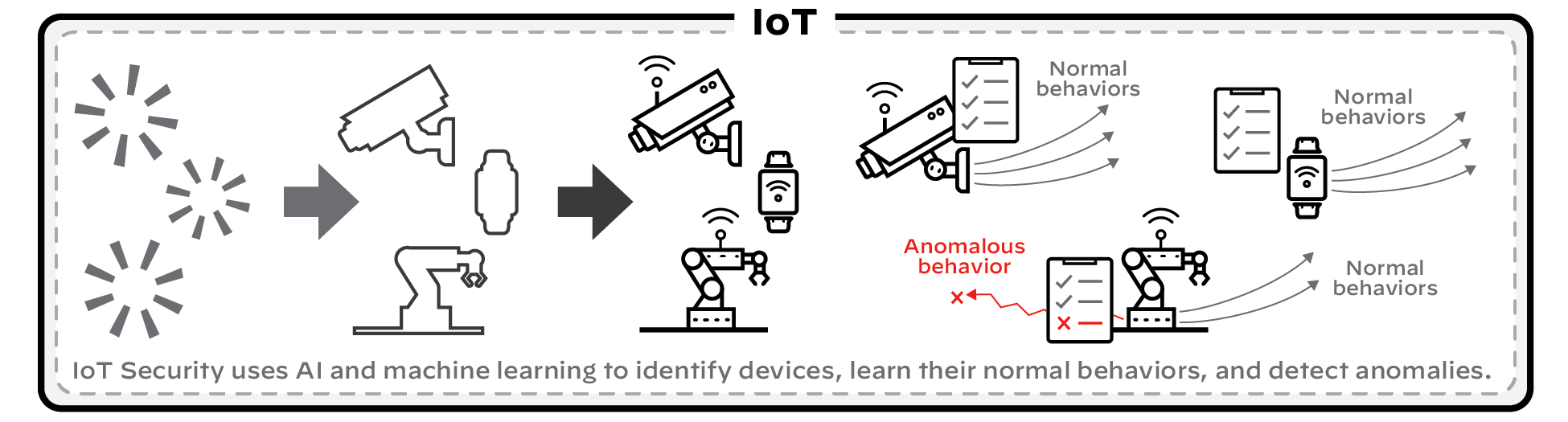
Figure: Data analysis process including device identification tiers, vulnerability detection, and alert generation.
Detailed Instructions: IoT Security Solution, Discover IoT Device and Take Inventory, Detect IoT Device Vulnerabilities, Respond to IoT Security Alerts documentation.
3 - IoT Device Protection
IoT Security coordinates with next-generation firewalls to recommend Security policy rules for IoT device traffic. After identifying devices and establishing a baseline of acceptable network behavior, IoT Security automatically generates recommended Security policy rules for device profiles based on the network behavior it observes. Panorama or firewall administrators then import the recommendations to Panorama or directly to firewalls where they decide which ones to add to their policy set.
Firewalls and Panorama must have a list of device profiles or other device attributes for Device-ID-based Security policy rules. This list is provided as a device dictionary file from the update server, which firewalls and Panorama check regularly for updates to download.
So that firewalls apply imported Device-ID-based rules appropriately, IoT Security continually sends the firewall IP address-to-device mappings , which include the profile and other attributes of all devices monitored and protected by IoT Security.
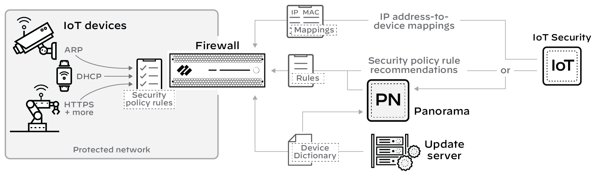
Figure: Policy enforcement flow from IoT Security recommendations/mappings to firewalls/Panorama.
IoT Security also integrates with Prisma Access to identify and secure devices.
Detailed Instructions: IoT Security Integration with Next-generation Firewalls, Recommend Security Policies documentation.
4 - Third-party Integrations
In addition to protecting IoT devices by coordinating with next-generation firewalls, IoT Security also integrates with third-party products to do the following:
- Increase device inventory and enrich device context—sometimes for IoT Security and sometimes for the integrated third-party product
- Broaden the coverage of specific features in integrated products to include IoT
- Expand the capabilities of IoT Security; for example, through integrations that allow you to do vulnerability scanning, quarantine devices with critical vulnerabilities or security alerts, and apply access control lists (ACLs) to IoT devices
IoT Security integrates with other products through a third-party integrations add-on, which is based on a Cortex XSOAR module.
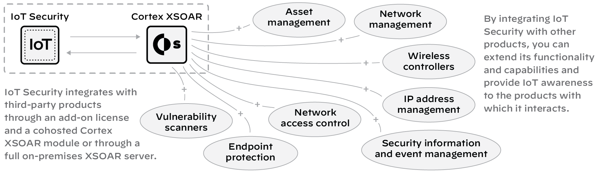
Figure: How IoT Security integrates with third-party products via Cortex XSOAR.
Detailed Instructions: IoT Security Integration Guide.
5 - Using Prisma Access instead of Next-generation Firewalls
When using IoT Security with Prisma Access, the process for collecting device data is similar to the previous description of data collection except that you substitute Prisma Access for firewalls. In addition, IoT Security can coordinate with Prisma SD-WAN ION devices to collect data at branch sites. When Prisma Access and SD-WAN forward data logs to the logging service, Strata Logging Service must be used.
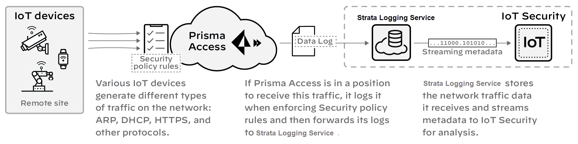
Figure: Data collection flow from Prisma Access and SD-WAN to Logging Service and IoT Security.
IoT Security sends Security policy rule recommendations through Panorama to Prisma Access. It sends IP address-to-device mappings to Prisma Access directly. Likewise, the update server sends device dictionary updates directly to Prisma Access as well as to Panorama.
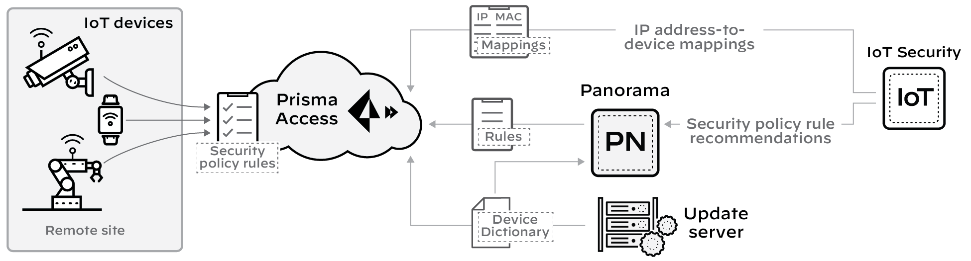
Figure: Flow of IP-to-device mappings, recommendations, and dictionary updates to Prisma Access and Panorama.
Detailed Instructions: Refer to Prisma Access integration section for details.
Activate IoT Security
Welcome to IoT Security activation. The IoT Security solution works with next-generation firewalls to dynamically discover and maintain a real-time inventory of the IoT devices on your network. If you are trying to activate IoT Security with the add-on Enterprise License Agreement (ELA), see activate an add-on enterprise license agreement documentation instead.
Because IoT Security requires network traffic data for analysis, you must enable firewalls to forward logs with that data to a cloud logging service that IoT Security can access. There are two types of IoT Security subscriptions:
- IoT Security Subscription - Doesn't Require Data Lake Subscription : (Available for all IoT Security products) This subscription sends data logs to a cloud logging service that streams them directly to IoT Security without storing them in a data lake.
- IoT Security Subscription : (Available on Enterprise IoT Security Plus, Industrial OT Security, and Medical IoT Security) This subscription requires a Strata Logging Service instance, which stores the data logs from firewalls. Firewalls forward logs to the logging service, which streams them directly to a Strata Logging Service instance and to IoT Security. You can use an existing, already activated Strata Logging Service instance or buy a new one to use.
In addition to the IoT Security subscription and possibly a Strata Logging Service subscription, you might have also purchased an IoT Security Third-party Integrations Add-on . This allows IoT Security to exchange information about devices, security alerts, and device vulnerabilities with third-party products... IoT Security supports third-party integrations through Cortex XSOAR.
Select Activate Subscription in your email, then use one of the following options:
- First time activation - one CSP account
- First time activation - multiple CSP accounts
- Return visit activation
First time activation - one CSP account
If you have only one Customer Support Portal account, follow these steps for first time IoT Security activation.
- Because you have only one Customer Support Portal account associated with your username, the Customer Support Account is prepopulated.
- Allocate the product to the Recipient of your choice. The name provided matches your Customer Support Portal account for convenience. You can use the name provided or change it.
- Choose the data ingestion Region , which is the region where the cloud logging service is receiving data from firewalls.
-
Strata Logging Service:
- If you are using IoT Security that doesn't require Strata Logging Service (available for all IoT Security products and the third party integration add-on), this sends data logs to a cloud logging service that streams them directly to IoT Security without storing them in a data lake. Skip to the App Subdomain step.
-
If you are using
IoT Security that does require Strata Logging Service
(available for Enterprise IoT Security Plus, Industrial OT Security, and Medical IoT Security), add
Strata Logging Service
.

Figure: Adding Strata Logging Service during activation for subscriptions that require it.
- Select a Strata Logging Service instance.
- Enter the amount of data log storage.
- The region is grayed out, but is autopopulated with the same region that you used for Strata Logging Service.
-
Enter an
App Subdomain
.
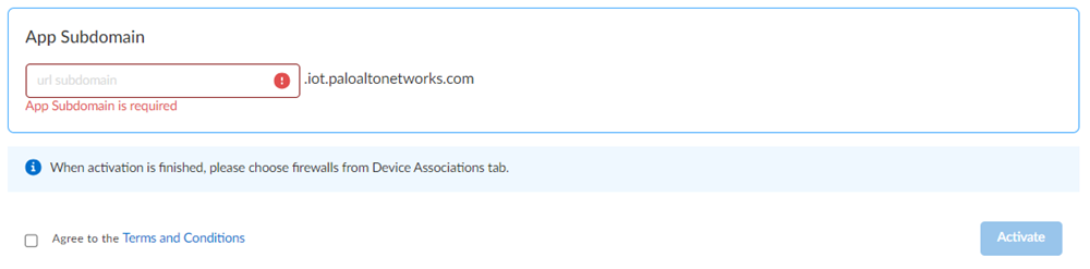
Figure: Entering a unique app subdomain for the IoT Security portal URL.
Use a unique subdomain to complete the <subdomain>.iot.paloaltonetworks.com URL for your IoT Security application. This will be the URL where you log in to the IoT Security portal. - Agree to the terms and conditions , and Activate . A single default tenant is autocreated behind the scenes, and the product is activated in the tenant. This tenant, and any others created by this Customer Support Portal account, will have the Superuser role.
- Go to the Common Services > Device Associations tab to add firewalls to the tenant, associate them with the IoT Security application, and then apply the IoT Security subscription to them.
- Get started with IoT Security.
- ( Optional ) Manage your product.
- ( Optional ) Manage identity and access.
First time activation - multiple CSP accounts
If you have multiple Customer Support Portal accounts, follow these steps for first time IoT Security activation.
-
If you have multiple Customer Support Portal accounts, choose the
Customer Support Account
number that you want to use.
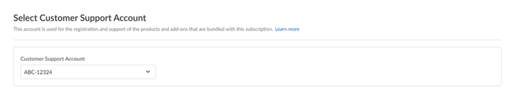
Figure: Selecting the desired Customer Support Account for activation.
-
Allocate the product to the
Recipient
of your choice. You can allocate your entire license to one recipient or you can share it with multiple recipients in a tenant hierarchy.
-
If you need just one tenant, use or rename the tenant provided. The name provided matches your Customer Support Portal account for convenience.
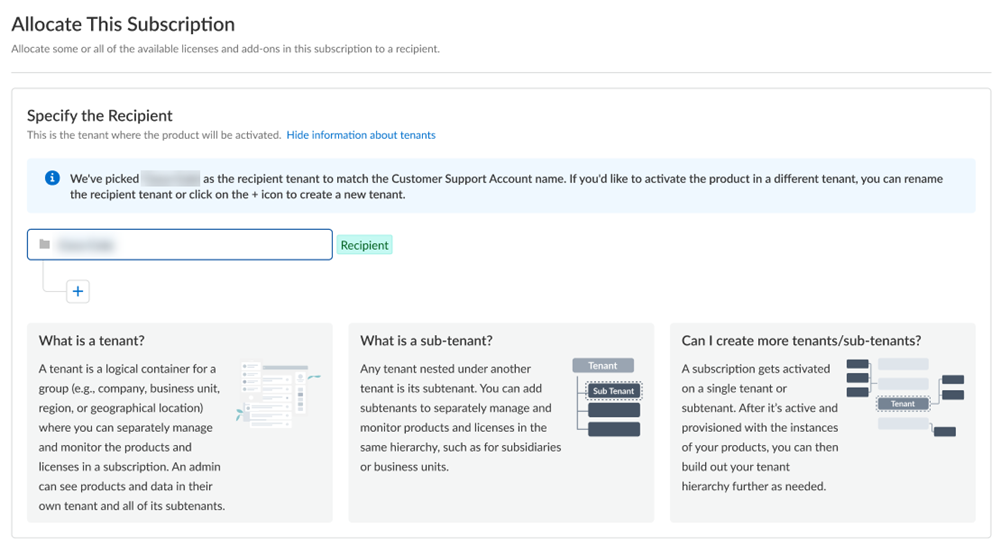
Figure: Selecting recipient and tenant name for single tenant scenario.
-
(
Optional
) This step applies if you are a managed security service provider (MSSP), a distributed enterprise customer, or need multiple tenants. After you create the first tenant, you can
Allocate to subtenant
and use or rename the tenant provided.
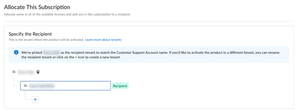
Figure: Allocating the subscription to a subtenant in a multi-tenant scenario.
A subscription gets allocated on a tenant or a sub-tenant. This step is for choosing a tenant where you want to allocate a license, not for building a complete tenant hierarchy. You can create only a tenant and subtenant here, and you can choose to allocate a license to that subtenant. After activation, you can build out your tenant hierarchy as needed through tenant management. You can create your tenant hierarchy to reflect your existing organizational structure. You can also consider identity and access inheritance when creating the hierarchy, in addition to tenant hierarchy limits. - Select Done .
-
If you need just one tenant, use or rename the tenant provided. The name provided matches your Customer Support Portal account for convenience.
- Choose the data ingestion Region , which is the region where the cloud logging service is receiving data from firewalls.
- Strata Logging Service: (See step 4 in "one CSP account" section, content is duplicated here)
- Enter an App Subdomain . (See step 5 in "one CSP account" section, content is duplicated here)
- Agree to the terms and conditions , and Activate . (See step 6 in "one CSP account" section, content is duplicated here)
- Go to the Common Services > Device Associations tab to add firewalls... (See step 7 in "one CSP account" section, content is duplicated here)
- Get started with IoT Security. (See step 8 in "one CSP account" section, content is duplicated here)
- ( Optional ) Manage your product. (See step 9 in "one CSP account" section, content is duplicated here)
- ( Optional ) Manage identity and access. (See step 10 in "one CSP account" section, content is duplicated here)
Note: Steps 4-10 for "First time activation - multiple CSP accounts" are the same as steps 4-10 for "First time activation - one CSP account" and guide through the selection of Logging Service, App Subdomain, agreement, activation, and subsequent steps.
Return visit activation
If you still have unused IoT Security licenses after completing the initial onboarding, you can return to the activation email and click the Activate button again. This allows you to repeat the process and activate more firewalls using the remaining licenses.
Onboard IoT Security
Follow the onboarding workflow to create a URL for your IoT Security portal and activate IoT Security subscriptions for your firewalls. Through the onboarding process, you can optionally activate a Strata Logging Service instance to store data and a third-party integration add-on for IoT Security to expand its capabilities.
It is important to keep the IoT Security activation email you received from Palo Alto Networks. It not only contains confidential activation-related data but if you still have unused IoT Security licenses after completing the onboarding process, you can click the Activate button in the email again to repeat the process and activate more firewalls later.
( Enterprise License Agreement ) When you have an Enterprise License Agreement (ELA), begin the activation process by entering the authorization code that Palo Alto Networks sends you in your Customer Support Portal account. For complete step-by-step instructions, see Activate an Add-on Enterprise License Agreement through Common Services documentation.
When you have IoT Security subscriptions, the onboarding process consists of the following main steps:
- Click Activate in the IoT Security activation email from Palo Alto Networks.
- Log in to the Palo Alto Networks hub.
- Activate IoT Security.
- Add devices (firewalls) to the tenant service group (TSG) and associate IoT Security, and possibly other applications as well, with the firewalls.
- ( Optional ) Manage identity and access to IoT Security.
- Set up IoT Security and firewalls to work together.
For instructions for these first six steps, see the Common Services: Subscription & Tenant Management documentation. Then return here to continue the setup.
-
FedRAMP solution
Submit a support request with the source IP addresses or source IP address blocks that you want to allow access to your FedRAMP IoT Security portal at
https://<your-domain>.iot-gov.paloaltonetworks.com.
- Sign in to the Palo Alto Networks Customer Support Portal.
- Create a Case to open a support request and provide the IP addresses or IP address blocks to allow access to your FedRAMP IoT Security portal.
- Log in to the IoT Security portal. Click the IoT Security link on either the Tenant Management or Device Associations page.
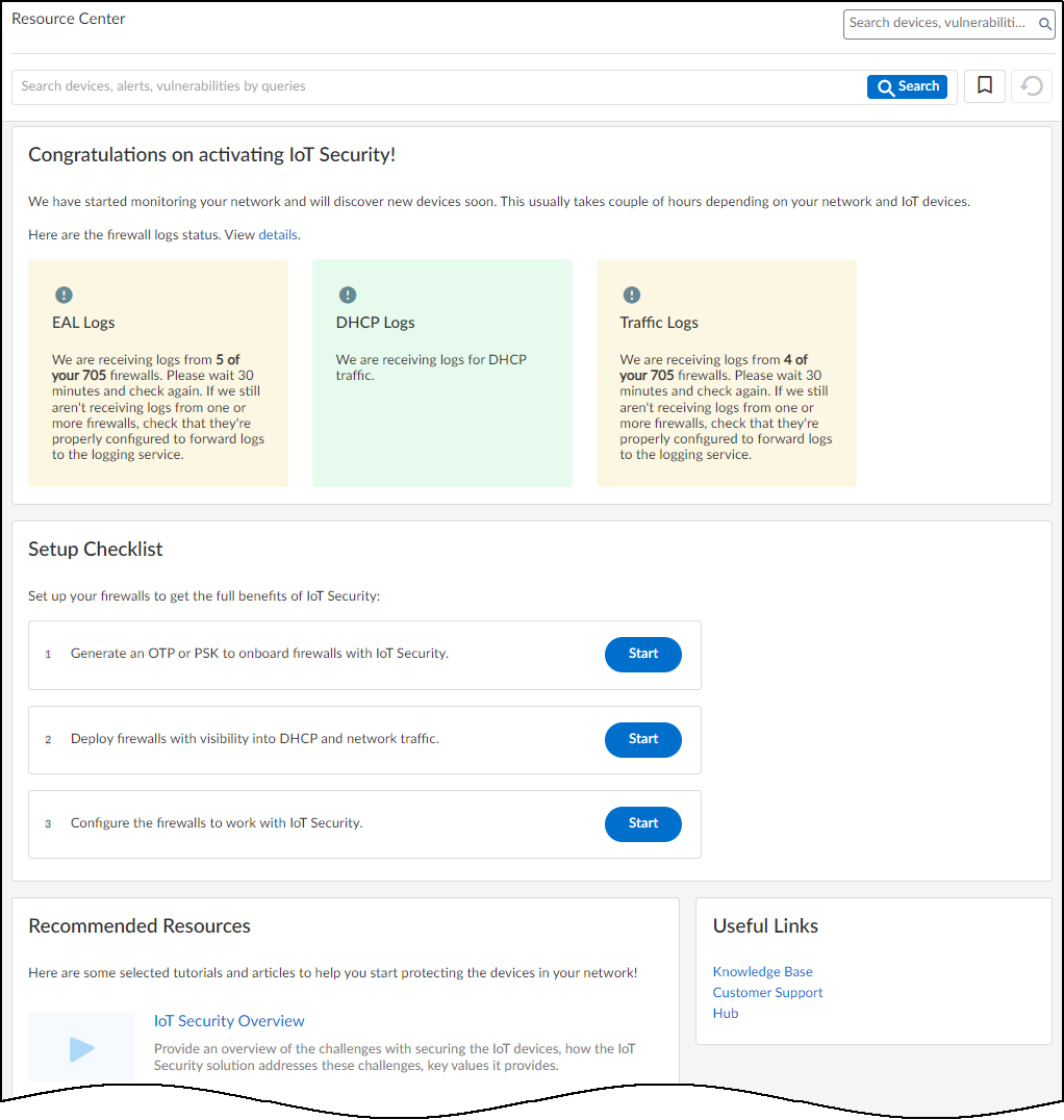
Figure: The IoT Security welcome page displayed upon first login.
A welcome page appears displaying the status of the logging service and several links to useful learning resources.
- To access the rest of the web interface, use the navigation menu on the left.
If you are a user with owner privileges and the portal doesn’t have a predetermined vertical theme, IoT Security will prompt you to select a theme when you attempt to navigate away from the welcome page: Enterprise IoT Security Plus, Industrial OT Security, or Medical IoT Security. If you don’t select a theme, you will use the Enterprise IoT Security Plus theme by default. IoT Security will continue to prompt you to select a theme every time you log in until you make a selection, or another user with owner privileges does.
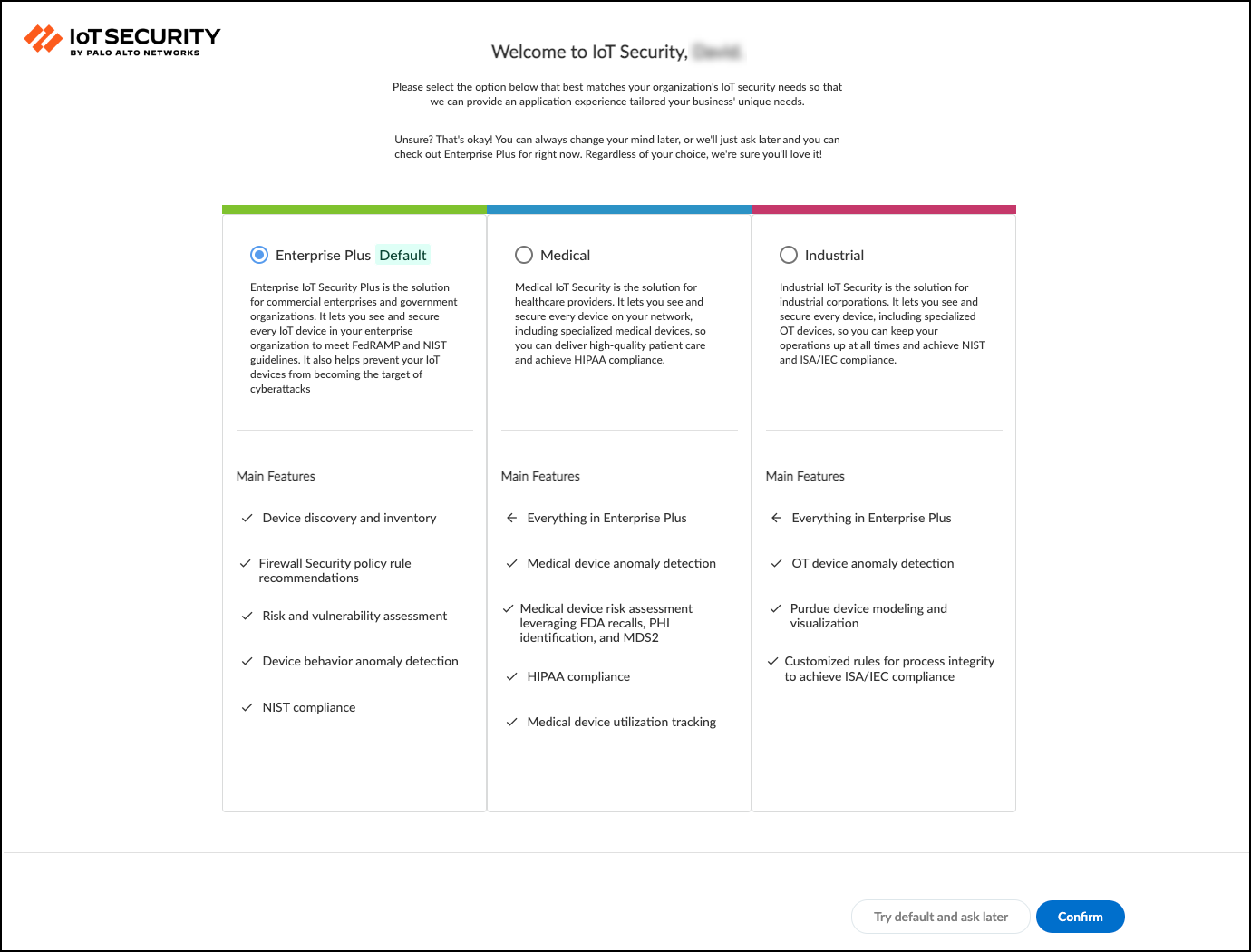
Figure: Prompt for selecting a vertical theme for the IoT Security portal.
If you are a user without owner privileges and an owner hasn’t yet selected a vertical theme, you will see the Enterprise IoT Security Plus theme by default. Otherwise, if the portal theme was already determined by the IoT Security product purchased or if an owner already set a theme, then that is the one you see.
There might not be any data in the portal when you first log in. Firewalls create network traffic data logs and forward them to the logging service, which streams them to the IoT Security Cloud. On average, devices begin showing up in the IoT Security portal within the first 30 minutes. Depending on the size of the network and the amount of activity of the devices on it, it can take several days for all the data to show up.
Click Administration > Sites and Firewalls > Firewalls in the IoT Security portal to see the status of logs that the logging service is streaming to the IoT Security app.
After the IoT Security portal has had time to use its machine-learning algorithms to analyze the network behavior of your IoT devices (1-2 days), consider following the typical workflow of an IoT Security user:
- Device visibility – Learn about the IoT devices on the network
- Application visibility – Learn about the applications and protocols these devices use
- Device vulnerabilities – Learn about IoT device vulnerabilities and take steps to mitigate them, first on the most critical devices and then on others
- Security alerts – Respond to security alerts as they occur, prioritizing your response on the urgency of the alert and the importance of the targeted device or network segment
- Security policy rule recommendations – Based on observed network behavior, the IoT Security app can generate recommended security policy rules that you can then sync with those on your next-generation firewall.
Depending on the PAN-OS versions running on your firewalls, you must generate an OTP or PSK and install certificates on firewalls so they will connect securely with the logging service and with IoT Security. There are also firewall configurations necessary to enable logging and log forwarding to IoT Security. For Enterprise IoT Security Plus, Industrial OT Security, and Medical IoT Security, you must also configure IoT Security and PAN-OS to apply Device-ID to enforce Security policy rules. To continue, see Prepare Your Firewall for IoT Security documentation.
Onboard IoT Security on VM-Series with Software NGFW Credits
A Palo Alto Networks VM-Series is a virtualized form factor of a Palo Alto Networks next-generation firewall and is intended for use in a virtualized or cloud environment. When you use Software NGFW credits to fund VM-Series with either fixed or flexible virtual CPUs (vCPUs), you can include IoT Security in the deployment profile during the firewall registration process.
You can also use Software NGFW credits to fund CN-Series with an IoT Security subscription as long as the firewalls are under Panorama management. For onboarding instructions of a CN-Series with IoT Security, see IoT Security documentation.
The following onboarding procedure is for VM-Series with an IoT Security subscription. It assumes that you have already purchased Software NGFW credits and activated them. At this point, you can use the Software NGFW credits to purchase VM-Series.
-
Create one or more deployment profiles for VM-Series. Create a deployment profile for each type of VM-Series model you want to deploy.
- Log in to the Customer Support Portal (CSP), and—if you have multiple accounts—choose the account you want to use.
- Select Products > Software NGFW Credits to view the Software NGFW Credits Dashboard.
- Locate your purchased NGFW Credits pool on the dashboard and Create Deployment Profile .
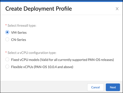
Figure: Creating a deployment profile for Software NGFW Credits in the CSP.
- Select VM Series and either Fixed vCPU models (Valid for all currently supported PAN-OS releases) or Flexible vCPUs (PAN-OS 10.0.4 and above) and then click Next .
- Assuming you selected Fixed vCPU models (Valid for all currently supported PAN-OS releases) , configure the following and then Create Deployment Profile :
Profile Name : Enter a name for the deployment profile.
Number of Firewalls : Enter the maximum number of firewalls that can be associated with this deployment profile.
Fixed vCPU model : Choose a VM-Series model from the list.
Security Use Case : Choose Custom .
Customize Subscriptions : Clear all preselected items and select IOT .
IOT Subscription : Choose the type of IoT Security subscription to activate on the VM-Series. The different types are based on vertical themes with or without traffic log retention in Strata Logging Service.
Use Credits to Enable VM Panorama : (clear all)
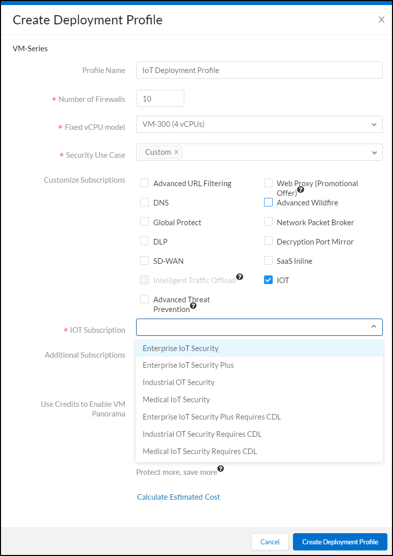
Figure: Configuring a deployment profile for VM-Series with IoT Security subscription.
After creating the deployment profile, it appears in the Current Deployment Profiles table on the Assets > Software NGFW Credits page.
- (Optional) After you click Create Deployment Profile , you can return to the configuration and click Calculate Estimated Cost to see an estimation of how many Flex credits will be deducted from your account and your remaining balance...
- If you have other types of firewall models to deploy, create additional deployment profiles, one for each type.
-
Activate IoT Security subscriptions based on the deployment profile in Common Services.
- Log in to the hub with your Palo Alto Networks Customer Support credentials. The hub fetches available deployment profiles for this account from the CSP.
- Select Common Services > Subscriptions & Add-ons . The deployment profile you created appears in the Ready for Activation section at the top of the page.
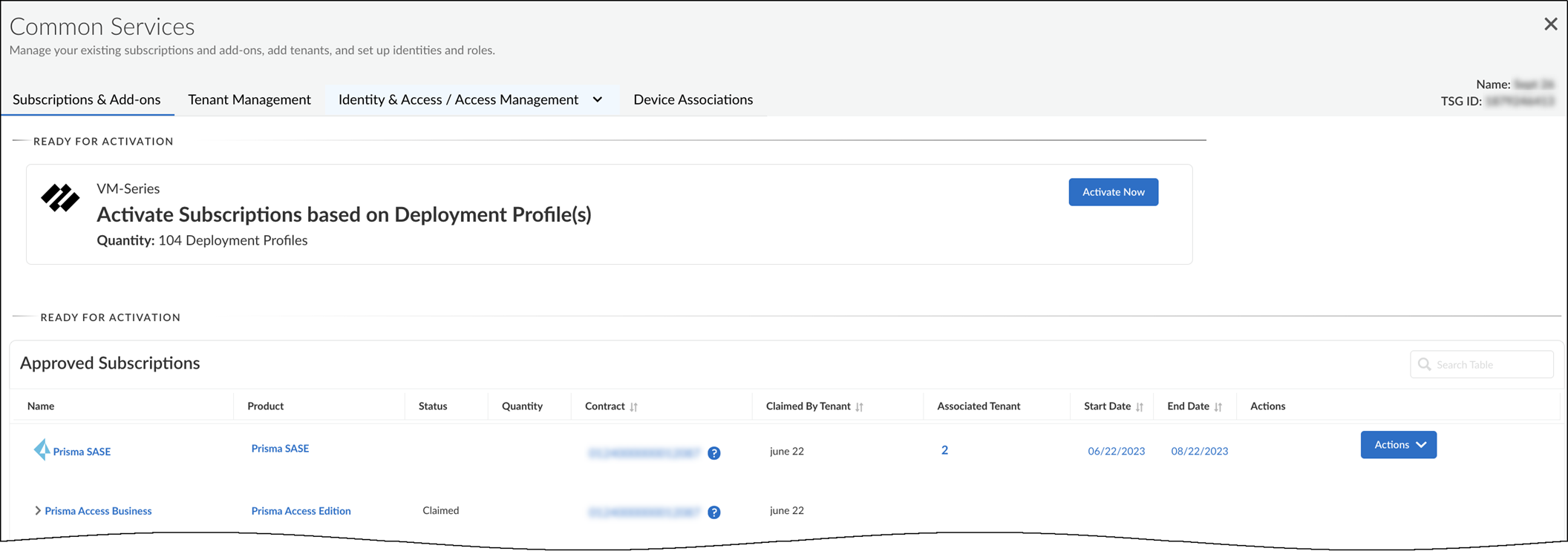
Figure: Deployment profile ready for activation in the hub.
- Click Activate Now . The Activate Subscriptions based on Deployment Profile(s) page appears.
- Configure the following IoT Security subscription activation settings:
Customer Support Account : Choose your CSP account with the deployment profile.
Recipient : Use an existing tenant or create a new one.
Select Region : When activating an IoT Security subscription that doesn’t require a Strata Logging Service, select the region... When activating an IoT Security subscription that does require a Strata Logging Service, you must first already have an activated Strata Logging Service instance in the same tenant service group (TSG)...
When you create multiple deployment profiles, it's possible that they have different IoT Security subscriptions. When using them in the same IoT tenant, the IoT Security subscription type in the first deployment profile takes precedence over others added afterward.
Select Deployment Profile(s) : Select the deployment profile you previously created.
Configure Subscription URL(s) : Enter a unique subdomain to complete the <subdomain>.iot.paloaltonetworks.com URL for your IoT Security application. This will be the URL where you log in to the IoT Security portal.
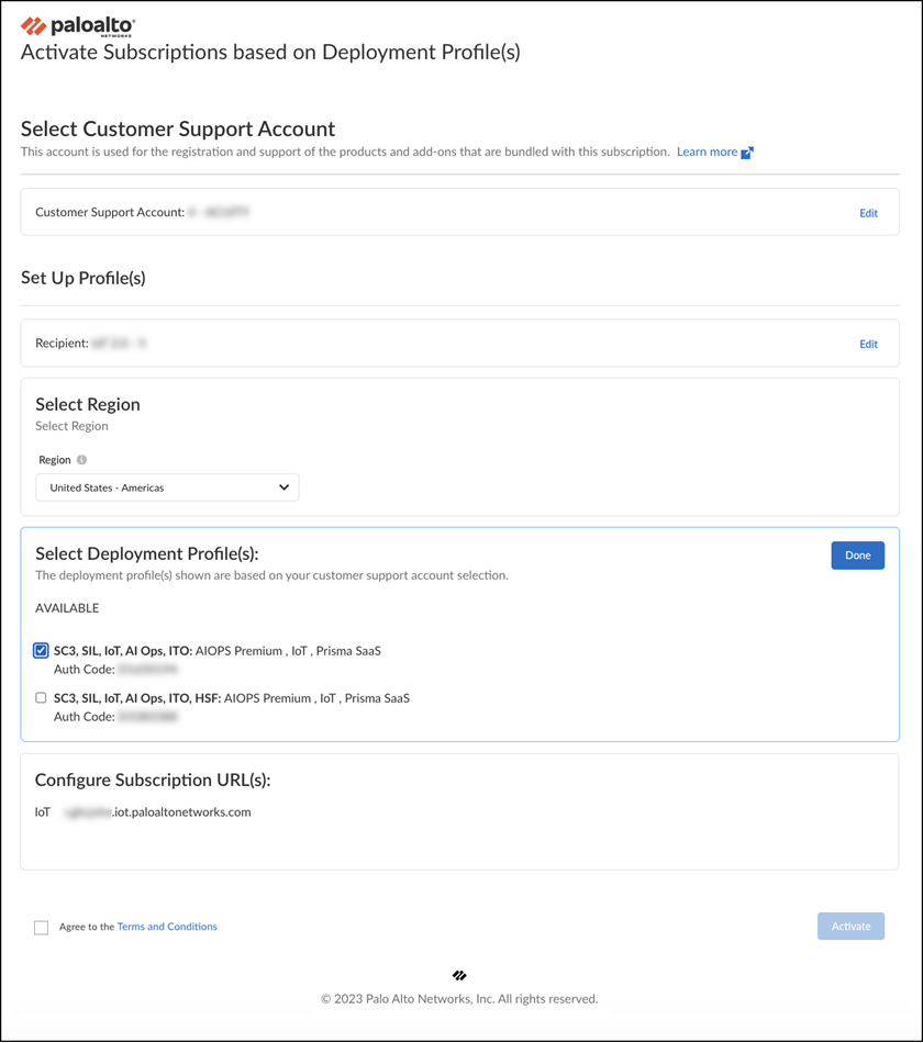
Figure: Configuring subscription activation settings for VM-Series.
- Agree to the Terms and Conditions and then Activate . The hub displays the Tenant Management page where you can see the IoT Security initialization status for the TSG. The initialization generally takes a few minutes to complete.
-
Associate firewalls through the deployment profile with the IoT Security subscription in the TSG.
- Register a VM-Series using one of the two methods described in Register the [VM-Series] documentation and then Submit the registration.
When registering a VM-Series that cannot access the CSP, you must enter a UUID, a CPU ID, the number of vCPUs on the firewall, and the amount memory allocated to the firewall... After you submit the firewall registration, the CSP associates this firewall through the deployment profile with the TSG. It typically takes a few minutes for the registration and association to complete. When completed, you can see the firewall on the Common Services > Device Associations tab in the hub.
During the firewall registration, the number of Software NGFW credits needed to fund the virtual firewall are automatically deducted from your pool of credits.
- Associate more firewalls to the TSG through the same deployment profile or, if they are different types of firewall models, through other deployment profiles you have created for them.
It’s not currently possible to extend, renew, or offboard IoT Security licenses that have been activated on VM-Series funded by Software NGFW credits. In addition, Enterprise License Agreements (ELA) and IoT Security FedRAMP Moderate licenses are not supported.
- Configure the VM-Series to provide network traffic logs with IoT Security. Now that you’ve onboarded IoT Security onto your VM-Series, follow the steps in Prepare Your Firewall for IoT Security documentation to configure it to log network traffic and forward the traffic logs to the logging service, which then streams network traffic metadata to IoT Security for analysis.
IoT Security Integration with Next-generation Firewalls
The IoT Security solution involves the integration of three key architectural components to process network data:
- Palo Alto Networks next-generation firewalls collect device data and send it to the logging service.
- The logging service uses a cloud-based log-forwarding process to direct the logs from firewalls to destinations like IoT Security and Strata Logging Service. Depending on the type of IoT Security subscription you have, the logging service either streams metadata to your IoT Security account and Strata Logging Service instance or just to your IoT Security account.
- IoT Security is an app that runs on a cloud-based platform in which machine learning, artificial intelligence, and threat intelligence are used to discover, classify, and secure the IoT devices on the network. The app ingests firewall logs with network traffic data and provides Security policy recommendations and IP address-to-device mappings to the firewall for use in Security policy rules. Administrators access the dynamically enriched IoT device inventory, detected device vulnerabilities, security alerts, and recommended policy sets through the IoT security portal.
The IoT Security app integrates with next-generation firewalls through Device-ID , which is a construct that uses device identity as a means to apply policy. The integration uses three mechanisms.
- Device dictionary – This is an XML file that IoT Security generates and makes available for Panorama and firewalls to import. The dictionary file provides the Panorama and firewall administrator with a list of device attributes for selection when importing recommended Security policy rules from IoT Security and when creating rules themselves. These attributes are profile, category, vendor, model, OS family, and OS version and are for both IoT and traditional IT devices... Panorama and firewalls automatically download and install updates from the update server every two hours.
- Policy rule recommendations – After an IoT Security administrator creates a set of Security policy rules based on traffic from IoT devices in the same device profile, a firewall administrator can import them as recommendations for use in its policy set. PAN-OS 8.1 and later supports the importing of policy rule recommendations.
- IP address-to-device mappings – These mappings tell firewalls which attributes a device with a particular IP address has. When traffic to or from that IP address reaches a firewall, it checks if one of its attributes matches a policy and, if so, the firewall applies the policy. IoT Security sends IP address-to-device mappings to firewalls for both IoT and IT devices if the confidence score for device identities is high (90-100%) and they’ve sent or received traffic within the past hour.
The goal of Device-ID is to leverage the intelligence of IoT Security to enforce firewall policy on IoT devices.
Device-ID
PAN-OS 10.0 introduces a new concept for policy enforcement: Device-ID. Device-ID is a way to enforce policy rules based on device attributes. IoT Security provides the firewall with a device dictionary file containing a list of device attributes such as profiles, categories, vendors, and models. For various attributes in the dictionary file, it lists a set of entries...
Currently, Device-ID is not supported on multi-vsys firewalls.
When configuring a Security policy rule, firewall administrators have the option to select device attributes from the device dictionary. If they select profile , they can choose one of the profile entries: Polycom IP Phone , for example. The policy rule then applies to all devices that match this profile. But how does the firewall know what the profile is for a device? It knows this from the IP address-to-device mappings that IoT Security also gives the firewall. These mappings identify attributes for each device. When traffic from an IP address that's mapped to a device attribute specified in the policy rule reaches the firewall, the policy rule lookup will find a match with this rule and apply whatever action it enforces.
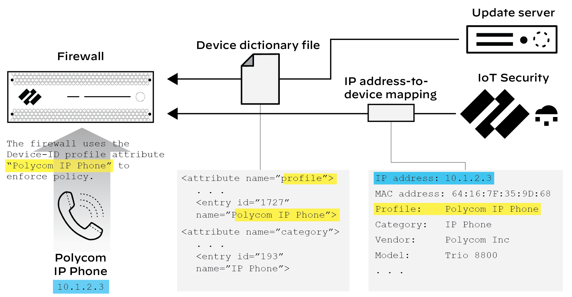
Figure: How Device-ID uses IP address-to-device mappings for policy enforcement.
If a firewall becomes disconnected from IoT Security, the firewall retains its IP address-to-device mappings and continues enforcing Device-ID policy rules with them until the connection is re-established.
Every next-generation firewall model has the same maximum of 1000 unique Device-ID objects.
The maximum of 1000 Device-ID objects is not the same as that for IP address-to-device mappings. The maximum number of IP address-to-device mappings varies based on firewall model and is the same as the User-ID maximums listed on the Product Selection page.
More information about the Device-ID feature is in the PAN-OS Administrator’s Guide.
Device Dictionary
The device dictionary is an XML file for firewalls to use in Security policy rules. It contains entries for the following device attributes: profile, category, vendor, model, OS family, and OS version. These entries come from devices across all IoT Security tenants and are completely refreshed on a regular basis and posted as a new file on the update server... Panorama and firewalls check regularly for updates to download automatically every two hours.
IP Address-to-device Mappings
After IoT Security identifies a device, it bundles the following set of identifying characteristics about it:
- IP address
- MAC address
- Hostname
- Device type
- Device category
- Device profile
- Vendor
- Model
- OS family
- OS version
- Risk score
- Risk level
Firewalls poll IoT Security for these IP address-to-device mappings for use in policy enforcement. A firewall polls for new or modified mappings every second, and IoT Security returns mappings that it has identified with high confidence (a confidence score of 90-100%) for devices that were active within the last hour. For each IP address-to-device mapping that a firewall receives, the firewall generates an entry in its host information profile (HIP) Match log.
If IoT Security discovers duplicate IP address-to-device mappings—that is, there are two IP addresses mapped to the same device MAC address— it resolves it to the MAC address with the latest network activity.
There is no time limit for how long a firewall retains IP address-to-device mappings. It only begins deleting them when its cache fills up, starting with the oldest first.
Policy Rule Recommendations
You can generate Security policy rule recommendations based on the normal, acceptable network behaviors of the IoT devices in the same device profile and manually import them into firewalls for enforcement. PAN-OS 8.1 and later supports the importing of policy rule recommendations.
For Panorama-managed firewalls that have an IoT Security subscription requiring Strata Logging Service – Panorama can only import policy rule recommendations if it was used to onboard its managed firewalls to Strata Logging Service.
Firewall and Panorama Communications Related to IoT Security
IoT Security communications from firewalls without Panorama management:
- Firewalls download device dictionary files from the update server at updates.paloaltonetworks.com on TCP port 443.
- Firewalls forward logs to the logging service on TCP ports 443 (for Enhanced Application logs) and 3978 (for all other firewall logs).
For details about the ports and FQDNs required for next-generation firewalls to communicate with the logging service, see the Strata Logging Service Getting Started documentation.
-
Firewalls retrieve IP address-to-device mappings and policy recommendations from IoT Security on TCP port 443. Depending on their region, they use one of the following edge services URLs:
- United States: iot.services-edge.paloaltonetworks.com
- Canada: ca.iot.services-edge.paloaltonetworks.com
- EU: eu.iot.services-edge.paloaltonetworks.com
- Switzerland: ch.iot.services-edge.paloaltonetworks.com
- United Kingdom: uk.iot.services-edge.paloaltonetworks.com
- APAC: apac.iot.services-edge.paloaltonetworks.com
- Japan: jp.iot.services-edge.paloaltonetworks.com
- Australia: au.iot.services-edge.paloaltonetworks.com
The following table summarizes the relationship of different data lake regions/ingestion regions with IoT Security application regions:
| Data Lake Region/Ingestion Region | IoT Security Application Region | |
|---|---|---|
| Americas | Canada | Canada, United States* |
| United States | United States | |
| FedRAMP | FedRAMP | |
| European Union | France | Germany |
| Germany | Germany | |
| Italy | Germany | |
| Netherlands | Germany | |
| Poland | Germany | |
| Spain | Germany | |
| Switzerland | Switzerland, Germany* | |
| United Kingdom | United Kingdom, Germany* | |
| Asia-Pacific | Australia | Australia, Singapore* |
| India | Singapore | |
| Indonesia | Singapore | |
| Japan | Japan | |
| Singapore | Singapore |
*Switzerland and the United Kingdom were added as IoT Security application regions on 7/31/2023... A similar situation exists in Canada, which continues to use United States – Americas as the IoT Security application region for deployments existing before 1/25/2023 and Canada for new deployments after this date. Likewise, deployments existing before 10/25/2022 in Australia still use the IoT Security application in Singapore while new deployments after this date use Australia .
-
During the certificate exchange between a firewall and the edge server in front of the IoT Security cloud, they verify each other’s certificates. The firewall validates the certificate it receives by checking these sites:
- *.o.lencr.org
- x1.c.lencr.org
Communications to these sites occur over HTTP on TCP port 80.
IoT Security communications from Panorama:
- A Panorama management server imports policy recommendations from IoT Security through the same URLs listed above that firewalls use. When validating the certificate the edge server presents, Panorama checks the same sites listed above that firewalls check.
Firewalls under Panorama management still contact IoT Security through regional edge services URLs for IP address-to-device mappings, they still download device dictionaries from the update server, and they still forward logs to the logging service.
- A Panorama management server sends queries for logs to the logging service on TCP port 444.
Prepare Your Firewall for IoT Security
The following steps describe how to enable Strata Logging Service on a Next-Generation Firewall and configure it to obtain and log network traffic metadata. It then explains how to forward the collected metadata in logs to the logging service where IoT Security uses it to identify various IoT devices on the network.
The steps below assume you already completed the IoT Security onboarding process but still need to do the following.
- Install a device license and a logging service license on your firewalls.
- Install certificates on your firewalls (if they are not installed already).
- Configure your firewalls to collect network traffic metadata.
- Configure your firewalls to forward the collected metadata in logs to the logging service.
- Enable Device-ID on zones with devices that you want to monitor and protect with Security policy rules.
- Optional Create service routes and Security policy rules to permit firewalls to communicate with the logging service, IoT Security, and the update server through a data interface.
Configuration Steps
- Install the licenses required for IoT Security to function. After onboarding to IoT Security, take one of the following actions to install the licenses your firewalls need to use IoT Security:
Next-generation firewalls : Log in to each of your firewalls, select Device > Licenses , and then select Retrieve license keys from license server in the License Management section.
or
Panorama : Log in to Panorama, select Panorama > Device Deployment > Licenses , and then Refresh . Select the devices onboarded with IoT Security and Refresh .
This installs the licenses for IoT Security and the logging service on the firewall.
When the time comes to renew IoT Security licenses, use this retrieval function on your firewalls so that they extend their license expiration dates.
- If necessary, generate a one-time password (OTP) and pre-shared key (PSK) to get device and logging service certificates.
This step only applies to firewalls with an IoT Security, Doesn't Require Data Lake Subscription. If your firewalls have an IoT Security Subscription, which requires Strata Logging Service, see the Strata Logging Service Getting Started documentation for details about generating certificates and installing them on your firewalls.
Skip this step if your firewalls run PAN-OS 10.1 or later and already have a device certificate installed. Any firewalls on which you’ve previously installed a device certificate for another Palo Alto Networks product already have this certificate and don’t require a new one. You can check if your firewall has a valid certificate in the General Information section on the Dashboard page in the PAN-OS web interface.
Firewalls running PAN-OS 10.1 or later require a device certificate but not a logging service certificate.
The following next-generation firewall models automatically install a device certificate when they first connect to the Customer Support Portal (CSP); therefore, you don’t have to install one manually on any of these firewalls running these PAN-OS versions:
- PAN-OS 10.1 : PA-410, PA-440, PA-450, PA-460, and PA-5450 firewalls
- PAN-OS 10.2 : PA-410, PA-440, PA-450, and PA-460 firewalls; PA-1400 Series and PA-3400 Series firewalls; PA-5410, PA-5420, PA-5430, and PA-5450 firewalls; and PA-7000 Series firewalls
- PAN-OS 11.0 and later : PA-400 Series, PA-400R Series, PA-1400 Series, PA-3400 Series, PA-5400 Series, PA-5450 firewalls, and PA-7000 Series
Also any firewalls on which you’ve previously installed a device certificate for another Palo Alto Networks product already have a device certificate and don’t require a new one.
Check the following questions and answers to determine when to generate and install a device certificate on a firewall.
| Do firewalls already have a device certificate? | Do firewalls already have a logging service certificate? | Are firewalls managed by Panorama? | What to do? |
|---|---|---|---|
| Yes | N/A | N/A | Skip this step. |
| No | N/A | Yes | Enter the Panorama serial number, generate an OTP in the Customer Support Portal, and enter it in Panorama to generate a device certificate. |
| No | N/A | No | Generate an OTP in the Customer Support Portal and install a device certificate on the firewall. |
For information about the sites that next-generation firewalls contact to authenticate certificates when communicating with IoT Security, see IoT Security Integration with Next-generation Firewalls documentation.
- Log in to the IoT Security portal as a user with owner privileges. To be able to generate OTPs and PSKs, your user account must have been created in the Customer Support Portal (CSP) and assigned a superuser role in the relevant tenant service group (TSG) in Identity & Access. A superuser role in the hub provides owner privileges in IoT Security.
- Select Administration > Firewalls > Certificate Generation .
- If you manage your firewalls with Panorama, choose Yes and enter its serial number. This will link your Panorama management server with the applications in this TSG... If you have an IoT Security license that includes Strata Logging Service, then Panorama must be part of the same TSG as Strata Logging Service.
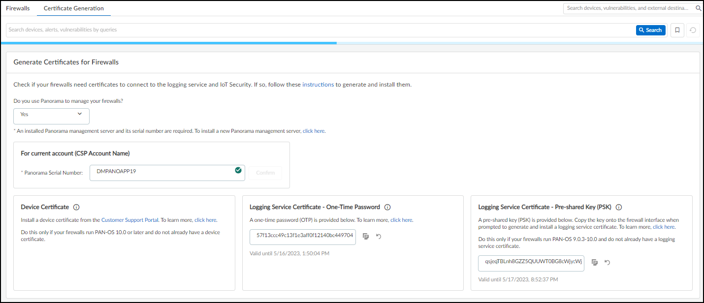
Figure: Certificate generation options when managing firewalls with Panorama.
To get a device certificate, click the link to the Customer Support Portal, log in to your account, and then follow the instructions below. To generate a logging service certificate, copy the OTP or PSK and follow the instructions below.
If you don’t use Panorama, choose No . Because an OTP for a logging service certificate applies only to Panorama, it's not shown.
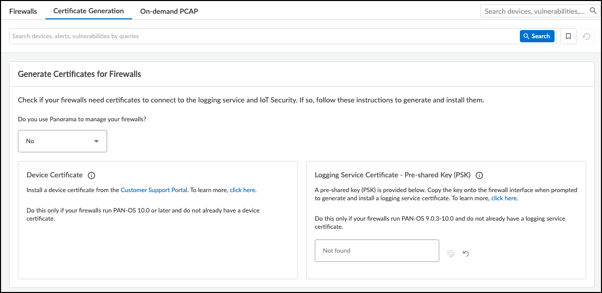
Figure: Certificate generation options when managing firewalls without Panorama.
Consider the following points when deciding which certificates you need and how to generate them:
Device Certificate : Firewalls require a device certificate to authenticate with IoT Security and to also authenticate with the logging service. To generate and install a device certificate on firewalls directly and through Panorama:
- Generate and install a device certificate on each firewall.
- Use Panorama to generate and install a device certificate on one or more firewalls.
When a device certificate is installed on a firewall so it can authenticate itself to the logging service and IoT Security, the firewall can’t decrypt encrypted traffic to inspect it and enforce policy rules on it. Therefore, don't try to use decryption policy rules on firewalls that have a device certificate installed on them.
Logging Service Certificate – One-Time Password : An OTP is necessary for Panorama to verify itself with its logging service instance and obtain logging service certificates for Panorama managed firewalls. A logging service certificate authenticates firewalls with the logging service.
- Regenerate the OTP if necessary and copy it.
- Log in to the Panorama web interface as an admin user and select Panorama > Setup > Management > Device Certificate and Get certificate .
- Paste the OTP and then click OK .
Logging Service Certificate – Pre-Shared Key : A PSK is necessary to generate a logging service certificate on firewalls without Panorama management running PAN-OS 9.0.3-10.0.x. A logging service certificate authenticates firewalls with the logging service. To generate a logging service certificate:
- Regenerate the PSK if necessary and copy it.
- Log in to your PAN-OS 9.0.3-10.0.x firewall and select Device > Setup > Management .
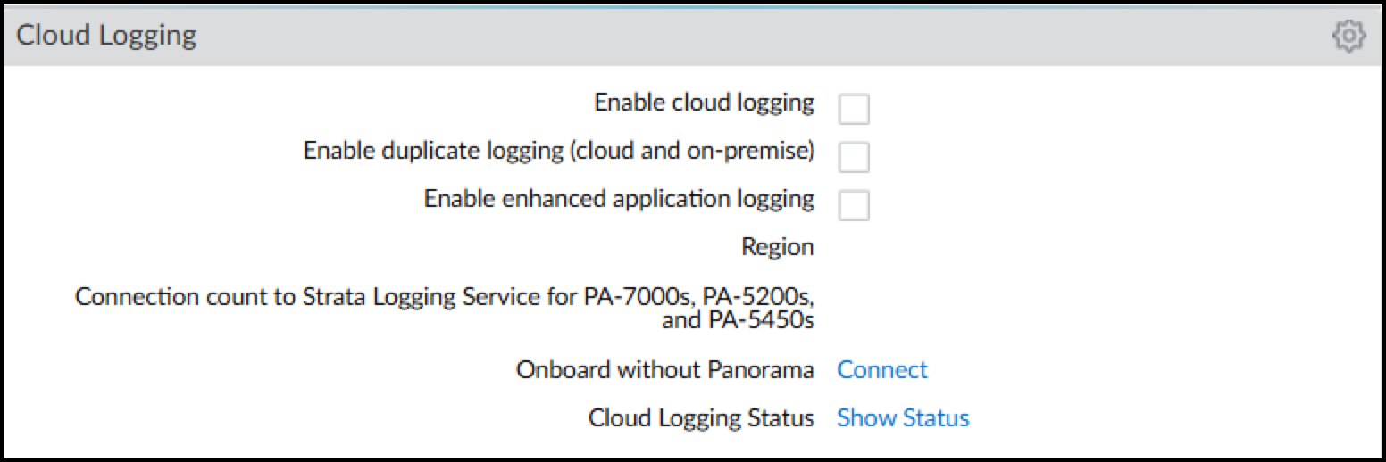
Figure: Location of Cloud Logging settings in the PAN-OS web interface.
- In the Cloud Logging section, click Connect next to Onboard without Panorama. This opens the Onboard without Panorama dialog.
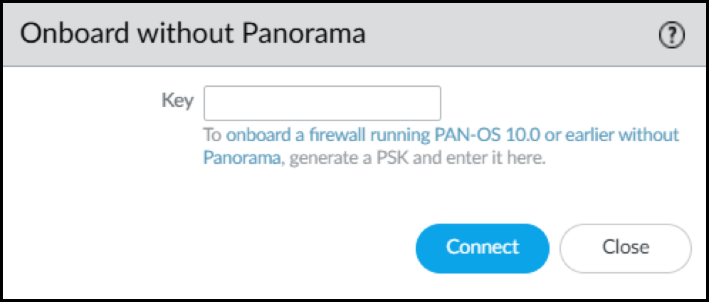
Figure: The Onboard without Panorama dialog for certificate generation using PSK.
- Paste the PSK and Connect . The firewall first connects to the Customer Support Portal, submits the PSK, and downloads a logging service certificate. It then uses the certificate to authenticate itself and connect securely to the logging service.
- Click the Edit icon (gear) for Cloud Logging. Select Enable Enhanced Application Logging .
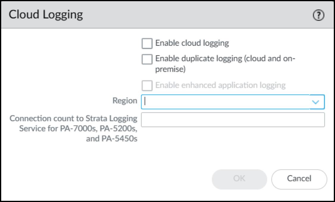
Figure: Enabling Enhanced Application Logging in Cloud Logging settings.
If you want to send the logs to the cloud logging service and to Panorama, also select Enable duplicate logging (cloud and on-premise) . If you don't need to send the logs to Panorama, select Enable cloud logging . Select one of these options in addition to enabling enhanced application logging. Panorama streams logs through cloud logging for IoT Security to ingest, even if you have a Doesn't Require Data Lake license.
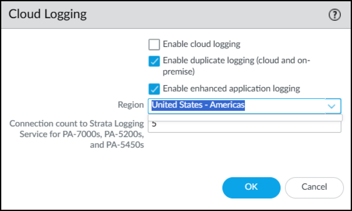
Figure: Additional Cloud Logging options including duplicate logging.
- Choose the region where Strata Logging Service will ingest logs from your firewalls. For PA-7000 and PA-5200 models, enter the number of connections for sending logs from the firewall to the logging service. The range is 1-20 and the default is 5.
- When done, click OK .
The term “Strata Logging Service” is a bit of a misnomer. The firewall forwards logs to Strata Logging Service, which only saves them to Strata Logging Service if you’re using it for data retention. An IoT Security, Doesn’t Require Data Lake subscription still uses Strata Logging Service to receive EAL logs from the firewall. Even if you have an IoT Security DRDL license, you need to enable Strata Logging Service so that the firewall can forward EAL logs to IoT Security.
- Make sure your firewall is set up to apply policy rules to DHCP traffic between DHCP clients and their DHCP server and to log their traffic.
For detailed instructions about setting up firewalls to capture and log DHCP traffic, see Firewall Deployment for Device Visibility documentation.
If the firewall has a DHCP server on one of its interfaces, enable DHCP Broadcast Session on Device > Setup > Session . This setting is supported on all firewalls running PAN-OS 10.1.10 or later, PAN-OS 10.2.4 or later, and PAN-OS 11.0.1 or later.
In addition to detecting devices with dynamically assigned IP addresses, IoT Security also discovers and identifies devices with static IP addresses. To learn about the multiple methods IoT Security uses to do this and how you can assist, see Devices with Static IP Addresses documentation.
- To forward logs to the logging service, click Objects > Log Forwarding and then check for an IoT Security Log Forwarding profile. By default, there is an IoT Security Default Profile preconfigured. This Log Forwarding profile sends Enhanced Application logs to the logging service so that IoT Security can ingest network traffic data. Optionally, you can add a new Log Forwarding profile or edit an existing one.
- Optional In the Log Forwarding profile, enter a name, click Enable enhanced application logs in cloud logging (including traffic and url logs) , and then click OK .
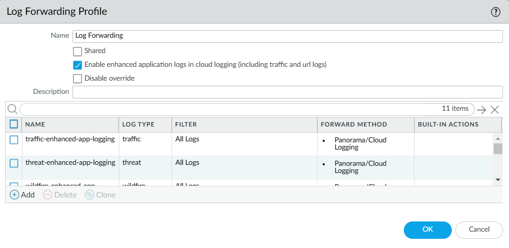
Figure: Configuring a Log Forwarding Profile for Enhanced Application logs.
A list of Enhanced Application logs automatically populates the page and forwards all logs per type to the logging service. Selecting Enable enhanced application logs in cloud logging (including traffic and url logs) enables the firewall to capture packet payload data (EALs) in addition to session metadata (regular logs) for these different log types... You can’t delete any of these logs from the profile nor modify any of the filters in the Filter column, which are the default "All Logs" filter.
The following describes each log type, explains if IoT Security uses it, and what its purpose is:
- traffic – Traffic logs contain entries for the end of each network session... IoT Security uses Traffic logs to identify devices, generate policy rule recommendations, risk assessment, device behavior anomaly detection, correlate sessions, and raise security alerts.
- threat – Threat logs contain entries for when network traffic matches one of the Security Profiles... IoT Security uses Threat logs to assess risks, detect vulnerabilities, raise security alerts, and generate policy rule recommendations.
- wildfire – WildFire® logs contain entries for when WildFire security profiles... IoT security uses WildFire logs to detect IoT-specific file-based attacks, raise security alerts, and generate policy rule recommendations.
- url – URL logs are written whenever network traffic matches a URL Filtering profile... IoT Security does not currently use URL filtering logs.
- data – Data logs can represent either a successful file data transfer or an attempted file transfer... IoT Security does not currently use data logs.
- gtp ( When GTP is enabled ) – GTP logs are written whenever a firewall is processing traffic from 3G, 4G, and 5G cellular devices. IoT Security uses the metadata from this traffic to identify cellular devices and their network behaviors...
- sctp ( When SCTP is enabled ) – SCTP logs are written whenever a firewall is processing stream control transmission protocol traffic. IoT Security does not currently use SCTP logs.
- tunnel – Tunnel logs are written whenever a firewall is processing generic routing encapsulation (GRE) or null encryption IPsec traffic... IoT Security does not currently use tunnel logs.
- auth – Auth logs contain information about authentication events... IoT Security does not currently use auth logs.
- decryption – Although IoT Security uses decrypted SSL data to improve device identification, risk assessment, and threat detections, it does not use decryption logs, which are helpful when troubleshooting issues with decryption.
The firewall automatically applies the IoT Security Default Profile to new Security policy rules when they’re created—or when they’re imported from IoT Security. This saves time and effort when importing Security policy rule recommendations from IoT Security... The default Log Forwarding profile is only applied when adding new Security policy rules, but it's not retroactively applied to existing rules.
- Enable log forwarding on Security policy rules. On Security policy rules that apply to traffic whose data you want to collect, enable log forwarding and choose the Log Forwarding profile you just created to send Enhanced Application logs for this traffic to the logging service. For information, see Configure Policies for Log Forwarding documentation.
- Enable Device-ID in each zone where you want to use it to detect devices and enforce your Security policy rules. For detailed configuration instructions, see Configure Device-ID in the PAN-OS Administrator’s Guide.
- ( Optional ) Create service routes and Security policy rules if your firewall uses a data interface to access Strata Logging Service, IoT Security, and the update server.
- Commit your configuration changes. After the configuration is committed, the firewall begins generating logs and forwarding them to the logging service. You can use the Explore app in the hub to see the progress of log forwarding between the firewall and the logging service.
Configure Service Routes for IoT Security
When you configure your next-generation firewall to obtain and log network traffic metadata, you can use a data interface to access Strata Logging Service and IoT Security. To use a data interface, you need to configure service routes and Security policy rules, and commit your configuration changes once you are done.
By default, the firewall uses its management interface to send data logs to the logging service, get recommended policy rule sets and IP address-to-device mappings from IoT Security, and download device dictionary files from the update server. When a firewall uses its management interface for all this, a service route and a Security policy rule are not needed.
However, when a firewall accesses the logging service, IoT Security, and update server through a data interface, then you must add a service route identifying the source data interface, source interface IP address, and service type. In addition, you must add an interzone Security policy rule permitting Data Services from 127.168.0.0/16 to the destination zone where the logging service, IoT Security, and update server are.
When a firewall generates traffic that it sends through a data interface, it uses an IP address in the 127.168.0.0/16 subnet as its internal source and then translates it to the IP address of the source interface. Because Security policy rules are applied to the original source IP address before NAT, the source IP address must be 127.168.0.0/16 instead of the IP address of the source interface.
Configure Service Routes
- If necessary, configure the data interface you want to use as the source interface for required IoT Security communications.
- Select Device > Setup > Services > Service Route Configuration and then select Customize .
- On the IPv4 tab, select Data Services , choose the data interface you want to use as the Source Interface, and then click OK . Its IP address autofills the Source Address field. This service route is for forwarding Enhanced Application logs (EALs) to the logging service.
Device-ID and IoT Security don’t support IPv6.
- Click IoT , choose the same data interface as the Source Interface, and then click OK . This service route is for pulling IP address-to-device mappings and policy rule recommendations from IoT Security.
- Click Palo Alto Networks Services , choose the same data interface, and then click OK . This service route is for forwarding other logs besides EALs to the logging service and for pulling device dictionary files from the update server.
- Click OK to save your configuration changes.
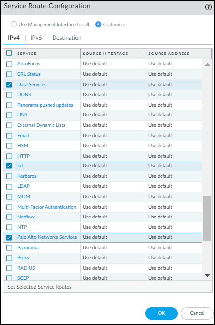
Figure: Configuring service routes for IoT, Data Services, and Palo Alto Networks Services.
Add Security Policy Rules
When you create services routes, you need to add Security policy rules permitting services required for the firewall to use IoT Security.
- Select Policies > Security > + Add .
- On the General tab, enter a name for the Security policy rule and choose interzone as the Rule Type.
- On the Source tab, select Any as the source zone and then Add 127.168.0.0/16 as the source address.
- On the Destination tab, Add the destination zone with IoT Security, and Add the edge services FQDN for your region as the destination address.
- On the Application tab, Add paloalto-iot-security . The firewall uses this application to pull IP address-to-device mappings and policy rule recommendations from IoT Security.
- On the Actions tab, choose Allow and then click OK .
- Create or select an intrapent policy rule that allows all intranet traffic in the zone where Strata Logging Service and the update server are.
If you have an intranet policy rule that allows all intranet traffi in the zone where the logging service and update server are, you can use that rule to allow the firewall to forward logs to Strata Logging Service and pull dictionary files from the update server.
Otherwise, create an intranet policy rule that allows the firewall to send these three applications to Strata Logging Service and update server from the IP address of the firewall interface in the same zone:
- paloalto-shared-services to forward EALs and session logs to the logging service
- paloalto-logging-service to forward other logs besides EALs to the logging service
- paloalto-updates to pull device dictionary files from the update server
Configure Policies for Log Forwarding
Enable log forwarding so that the firewall sends Enhanced Application logs (EALs) to the Palo Alto Networks cloud-based logging service. IoT Security then fetches metadata from there for analysis.
Configure an Interzone Policy
If the VLAN interfaces are set in different L3 security zones from the Ethernet interfaces with which they’re paired, Security policy rules must be configured for the solution to work. The figure below shows example rules when multiple VLAN interfaces have been configured to support multiple Ethernet interfaces.
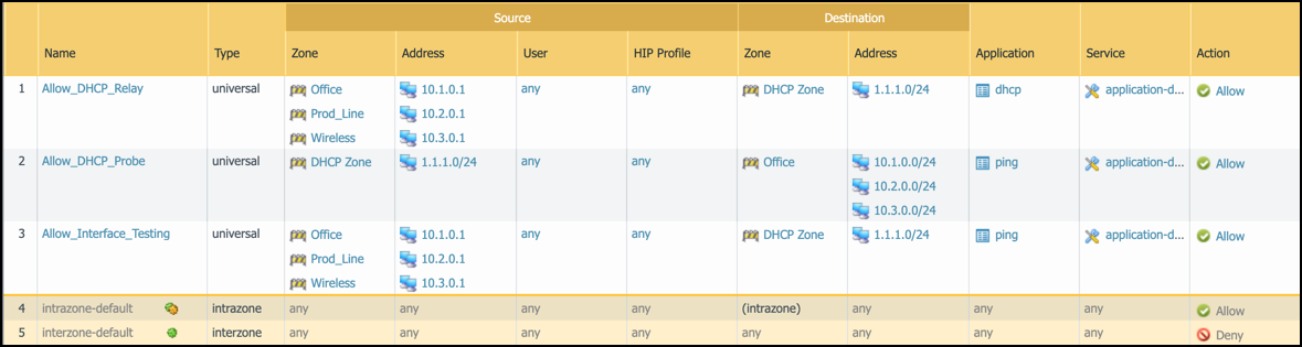
Figure: Example interzone Security policy rules for log forwarding.
- Policy rule 1: This policy rule allows relayed unicast DHCP messages from the zones assigned to interfaces ethernet1/1 - ethernet1/3 to the DHCP zone. In addition, enable log forwarding and choose the log-forwarding profile you previously created to send EALs for this traffic to the logging service. If you name the log forwarding profile “default” (all lowercase), the firewall will automatically apply it to new Security policy rules when they’re created—or when they’re imported from IoT Security... (Note that the “default” log forwarding profile will be applied when adding new Security policy rules, but it won’t be retroactively applied to existing rules.)
- Policy rule 2: This rule allows ping (ICMP echo requests) from the VLAN interfaces in the DHCP zone to networks configured on ethernet1/1 - ethernet1/3.
- Policy rule 3: This rule allows ping from the IP addresses assigned to ethernet1/1 - ethernet1/3 to VLAN interfaces configured in the DHCP zone.
Configure an Intrazone Policy
You must override the logging and log forwarding settings in the default intrazone policy rule so that the firewall will forward logs to the logging service.
If the interface hosting the DHCP server is in the same zone as the interface your clients are on, the default intrazone policy rule applies to this traffic, which, by default, allows all traffic within this zone but does not have logging and log forwarding enabled. Therefore, you must override this by enabling log forwarding on your default intrazone policy rule.
Even for cases where the DHCP server is in a different zone from the DHCP clients and an interzone policy is applied to their DHCP traffic, we still recommend that you enable log forwarding on the default intrazone policy rule to capture the enhanced application logs for traffic within that zone.
- Click Policies > Security , select intrazone-default , and then click Override . The Security Policy Rule configuration window appears.
- Click Actions , select Log at Session End , choose the log forwarding profile you just configured from the Log Forwarding drop-down list, and then click OK .
Firewall Deployment for Device Visibility
The Palo Alto Networks IoT Security app uses machine learning to classify IoT devices based on the network traffic for which these devices are either a source or destination. To accomplish this, it relies on Enhanced Application logs (EALs) generated by the Palo Alto Networks Next-Generation Firewall.
DHCP traffic is of particular importance to the IoT Security solution. DHCP provides a way to create an IP address-to-device mapping (that is, an IP address-to-MAC address mapping) that is required for classification to take place. However, a firewall typically only generates an EAL entry when it receives a unicast DHCP message; for example, when there is centralized Internet Protocol address management (IPAM) and either the firewall or another local device acts as a DHCP relay agent. Below is an example architecture that illustrates a common case where the firewall generates EALs for unicast DHCP traffic.
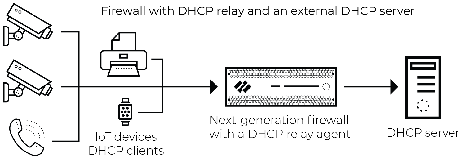
Figure: Network architecture showing unicast DHCP traffic through a firewall acting as a relay.
The firewall generates an EAL entry for broadcast DHCP traffic when the packet is seen on a virtual wire (vWire) interface with multicast firewalling enabled, as shown below.
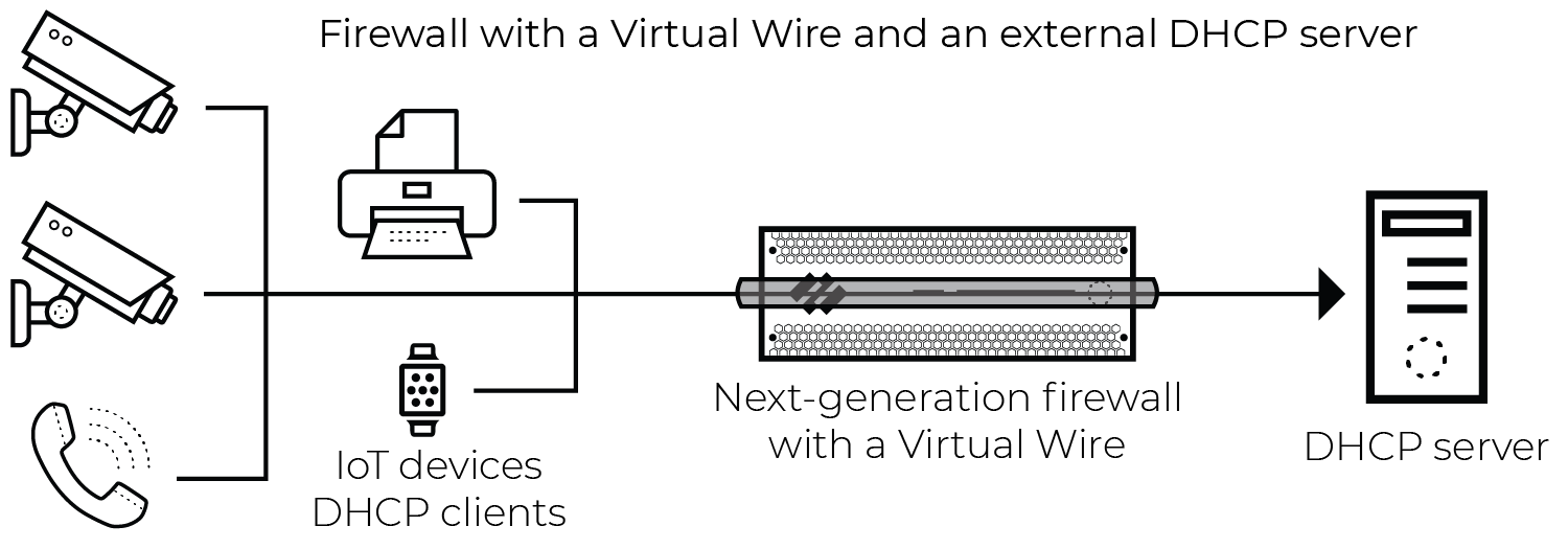
Figure: Network architecture showing broadcast DHCP traffic captured by a firewall via a Virtual Wire interface.
DHCP Data Collection by Traffic Type
The tables below show Enhanced Application log (EAL) coverage when the firewall interface receiving unicast and broadcast DHCP traffic is in different modes.
Unicast DHCP Traffic
| Firewall Interface Deployment Mode | DHCP EAL Generated |
|---|---|
| Virtual Wire | Yes |
| Tap | Yes |
| Layer 2 | Yes |
| Layer 3 | Yes |
Broadcast DHCP Traffic
| Firewall Interface Deployment Mode | DHCP EAL Generated |
|---|---|
| Virtual Wire | Yes |
| Tap | No |
| Layer 2 | No |
| Layer 3 | No |
| DHCP server on the firewall (L3, L2 with VLAN interface) | Yes* |
| DHCP relay agent on the firewall (L3, L2 with VLAN interface) | Yes |
*A firewall running a PAN-OS 10.0 release or later natively generates EALs when a DHCP server is configured on an interface, DHCP Broadcast Session is enabled, and there’s a Security policy rule that allows DHCP traffic to reach the server and has EAL forwarding enabled. For more information, see Prepare Your Firewall for IoT Security and Configure Policies for Log Forwarding documentation.
Firewall Deployment Options for IoT Security
When assessing deployment options for IoT device visibility, there are two fundamental considerations:
- The firewall must see traffic for the IoT application to use network traffic data for classification and analysis and for the enforcement of policy rules on the firewall itself. This includes regular operational traffic in addition to DHCP traffic.
- With the exceptions outlined below, the firewall must see unicast DHCP traffic to generate the data that allows IoT Security to create the required IP address-to-device mappings.
Exceptions to the Unicast Rule
- Virtual Wire: When the firewall has Virtual Wire interfaces with multicast firewalling enabled, it generates Enhanced Application logs (EALs) for broadcast DHCP sessions.
- A DHCP server is configured on the firewall: No workaround is required for the firewall to generate EALs when a DHCP server on one of its interfaces receives broadcast DHCP traffic. Just enable DHCP Broadcast Session at Device > Setup > Session .
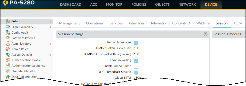
Figure: Enabling DHCP Broadcast Session in PAN-OS Session settings.
When the firewall receives DHCP broadcast traffic and applies a policy rule with an Enhanced Application log forwarding profile, it logs the DHCP traffic and forwards it to the logging service. From there, IoT Security accesses the data for analysis.
-
A DHCP relay agent is configured on the firewall:
- The firewall generates EALs for broadcast DHCP traffic when a DHCP relay agent is configured on one of its interfaces.
The following sections detail specific deployment options for increasing device visibility.
Use a Tap Interface for DHCP Visibility
To gain complete visibility of DHCP traffic, deploy a Tap interface on the firewall. This guide assumes familiarity with PAN-OS configuration, including Tap configuration.
Considerations
Sending additional traffic to a Tap interface on the firewall results in additional session load. There are two causes for this:
- Any flow from the DHCP server to the internet, data center, or some other destination that would normally cross the firewall is inspected twice.
- Flows that normally would not be inspected are inspected when the Tap interface receives them; for example, flows bound for other hosts on the local network segment.
The following configuration section includes options for minimizing performance impact.
Network Architecture
The figure below illustrates the general idea of this solution. The actual topology can vary depending on the location of the DHCP server and the use of technologies such as RSPAN (Remote Switched Port Analyzer).
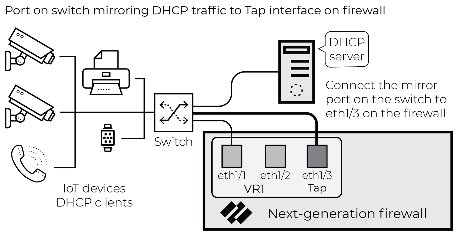
Figure: Network architecture showing a Tap interface used to mirror DHCP traffic.
The purpose of this configuration is to gain visibility into DHCP traffic that the firewall wouldn’t normally see based on its current configuration and network topology.
Configuration
- Configure a Tap interface and zone.
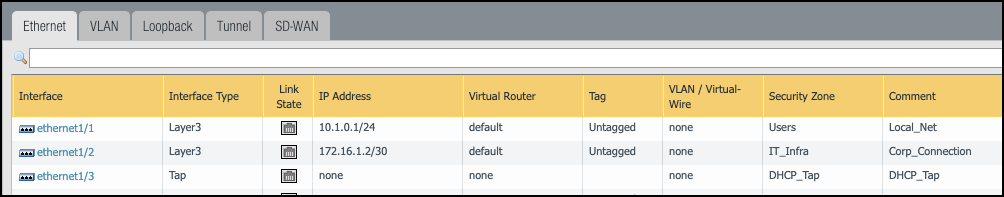
Figure: Configuring a Tap interface and assigning it to a zone.
- Configure policy rules for Tap traffic.
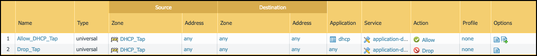
Figure: Example policy rules for handling traffic received on a Tap interface.
- The first policy rule matches DHCP traffic and uses the same log forwarding profile that the rest of the rule base uses.
- The second rule drops all other traffic, minimizing additional session load on the firewall. Log forwarding profile is not enabled.
- Neither of the rules use security profiles.
- Connect the Tap interface to the port mirror on the switch.
Use a Virtual Wire Interface for DHCP Visibility
To gain complete visibility of DHCP traffic, deploy a Virtual Wire (vWire) in front of the DHCP server. This guide assumes familiarity with PAN-OS configuration, including Virtual Wire configuration.
Network Architecture
This solution is for networks where a DHCP server is on the same network segment as the firewall interface, as shown in the figure below.
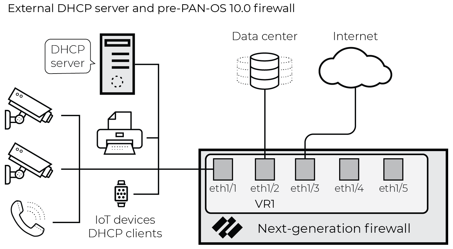
Figure: Network architecture where a DHCP server is on the same network segment as a firewall interface.
For full visibility of all four DHCP messages, place the DHCP server behind a Virtual Wire interface. Doing so enables the firewall to generate Enhanced Application logs (EALs) for all packets in the exchange. After proper configuration and physical network changes, the network looks similar to the following illustration:
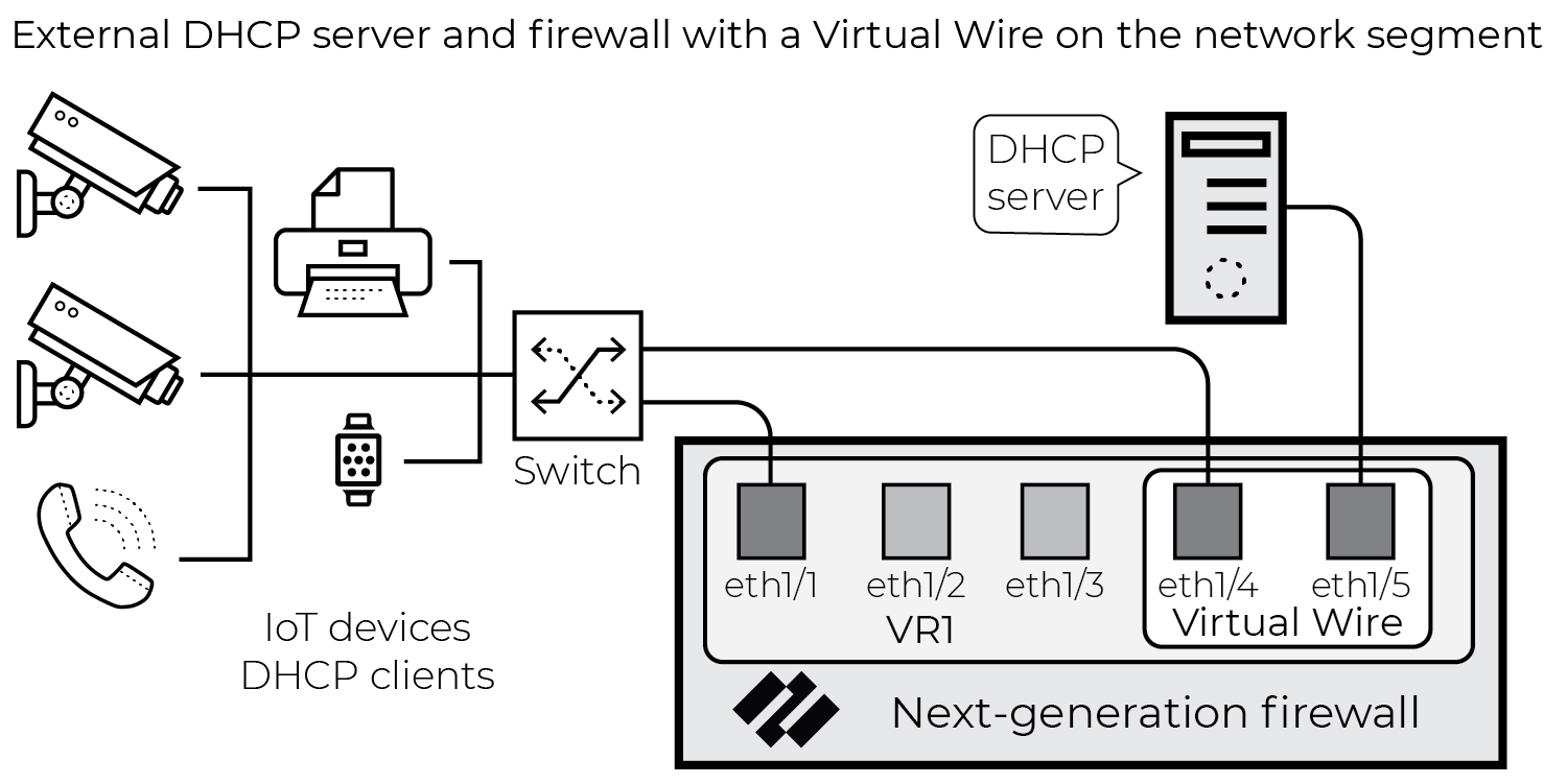
Figure: Network architecture where the DHCP server is placed behind a Virtual Wire interface on the firewall.
Configuration
- Configure a Virtual Wire interface, complete with zones. The configuration of the Virtual Wire object must include multicast firewalling:
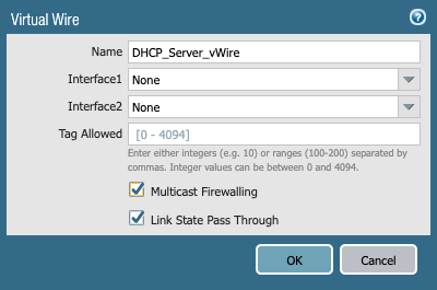
Figure: Configuring a Virtual Wire interface and enabling multicast firewalling.
- Configure a policy rule to allow traffic between the two Virtual Wire interface zones. Configure this policy rule to allow all the existing traffic that the server currently sees use the same log forwarding object as the rest of the rule base. The Policy Optimization section below covers optimizing this policy rule set and preventing double logging.
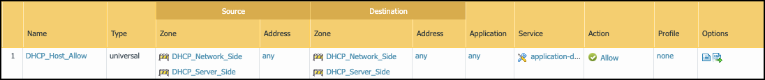
Figure: Example policy rule allowing traffic between zones connected by a Virtual Wire.
- Connect the external DHCP server to one side of the Virtual Wire and connect the network switch to the other side. Instead of connecting the DHCP server host directly to the firewall, you can use an isolated VLAN to minimize cabling in the switching infrastructure.
Policy Optimization
The goal of this solution is to gain visibility into DHCP payloads while minimizing performance impact on the firewall. To that end, configure the following policy rule set for the Virtual Wire zones:
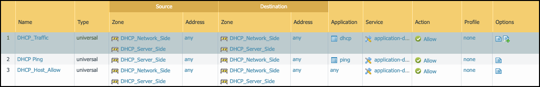
Figure: Optimized policy rules for Virtual Wire interfaces to capture DHCP and minimize load.
- The “DHCP_Traffic” policy rule allows DHCP to and from the DHCP server. This rule uses the standard log forwarding profile with EALs enabled.
- The “DHCP Ping” policy rule allows pings from the DHCP server to the rest of the subnet. This enables DHCP servers to check if an IP address is active before assigning it as a lease to a new request. This rule does not forward logs.
- The “DHCP_Host_Allow” policy rule allows everything else to and from the DHCP server and does not forward logs for traffic matches.
To minimize the performance impact... security profiles are not assigned to the above policy rules. If you want to microsegment the DHCP server, replace the “DHCP_Host_Allow” rule with a more granular policy rule set that allows applications in accordance with best practices. You can use security profiles in that policy rule set.
Use SNMP Network Discovery to Learn about Devices from Switches
To identify devices, assess risk, and help next-generation firewalls enforce Security policy rules based on Device-ID, IoT Security requires network traffic metadata for analysis... When firewalls don’t receive traffic from all devices or when they do but it contains only IP addresses—possibly because the traffic crossed Layer 2 domains and the device MAC address was changed to that of the forwarding device—they can still gather IP address-to-MAC address bindings by using SNMP to query switches throughout the network.
When using SNMP to query network switches and other forwarding devices, firewalls first develop a network topography by requesting the Link Layer Discovery Protocol (LLDP) neighbors and Cisco Discovery Protocol (CDP) neighbors of one switch (the entry point switch) and then repeating the request with neighboring switches and child switches one by one throughout the network. After obtaining a list of switches and forwarding devices throughout the network, or within a limited area of the network, the firewall next queries each one for its ARP table as well as other information... After the firewall receives this information, it creates logs and sends them through the logging service to IoT Security.
The following are sample object identifiers (OIDs) that SNMP queries on UDP port 161 for information about LLDP neighbors and CDP neighbors, device IP address-to-MAC address bindings, and interface or port information:
- OID: 1.0.8802.1.1.2.1.4 lldpRemoteSystemsData (LLDP neighbors)
- OID: 1.3.6.1.4.1.9.9.23 ciscoCdpMIB (CDP neighbors)
- OID: 1.3.6.1.2.1.4.22.1.2 ipNetToMediaPhysAddress (IP-to-MAC address bindings from ARP)
- OID: 1.3.6.1.2.1.4.22.1.1 ipNetToMediaIfIndex (Interface or port information)
SNMP network discovery is available to NGFWs as part of the free Network Discovery plugin and does not require an add-on license... Alternatively, IoT Security provides SNMP Network Discovery as part of the IoT Security Third-party Integrations Add-on license , which must be purchased. Both the version using the add-on license and the version with the free plugin supports multiple sets of jobs for different networks and network segments per IoT Security tenant.
The SNMP network discovery process can’t traverse switches that don’t support CDP or LLDP.
To configure SNMP Network Discovery with the plugin, you need to have a next-generation firewall with an associated IoT Security license... From the management interface of your NGFW, download the Network Discovery plugin...
Configure SNMP Network Discovery with the Plugin
The following instructions are for the Network Discovery plugin configuration using the PAN-OS web interface on an individual next-generation firewall. To configure the plugin on Panorama, use templates and template stacks and template stack variables...
- Open the SNMP settings for the Network Discovery plugin. Select Device > IoT Security > Network Discovery . In the SNMP Network Discovery section, click Edit (gear icon). The SNMP Network Discovery Settings dialog box appears... Select Enable SNMP Network Discovery Settings to configure SNMP Network Discovery.
- Schedule how often the firewall runs an SNMP crawl job. In the Network Discovery Job section, schedule how often the firewall runs a job to learn all the switches and other network forwarding devices that run LLDP and CDP on the network or within a defined scope... The default is once a day...
- Schedule how often the firewall queries for information about the network and connected devices. In the Network Data Refreshment Job section, schedule how often the firewall runs a job... Consider how often DHCP lease times renew and schedule the job to run at half the lease time... In environments without DHCP, consider running the network data refreshment job once every hour, which is the default setting.
-
Click the
Discovery Scope Settings
tab and configure the scope of the SNMP crawl.
- Entry Point switch : Enter the IP address of the entry point switch...
- Device IP Address Scope : Enter the prefix for the IP CIDR block... Optionally, don’t set a scope by entering None and SNMP will collect network topology for the entire network.
- Maximum Number of Hops : Enter the number of switches away from the entry point switch... The default number of hops is 10.
- Site : Add the name of the site where the SNMP job queries switches...
- Service Route : If your firewall uses a data interface rather than the management interface..., set a service route... Service routes configured on Device > Setup > Services > Service Route Configuration are not applied. SNMP network discovery only uses service routes configured here.
-
Click the
SNMP Settings
tab and configure the SNMP credentials... Set the SNMP version and configure the required settings for the version and options you use.
- SNMP Version : Choose V2 or V3.
- Community String (for SNMP V2): Enter the SNMP community string...
- Username (for SNMP V3): Enter a username...
- Security Level (for SNMP V3): Choose noAuthNoPriv, authNoPriv, or authPriv.
- Authentication Protocol (for SNMP V3): Choose MD5 or SHA.
- Authentication Password (for SNMP V3): Enter the password...
- Privacy Protocol (for SNMP V3): Choose DES or AES.
- Privacy Password (for SNMP V3): Enter the password...
- Retries : Enter the number of times the job should try an SNMP query... The default number of retries is 2.
- Timeout (ms) : Enter the time that the job should wait for a response... The default timeout is 2000 ms.
-
Click
OK
to save your SNMP Network Discovery settings. After enabling this feature, the settings are sent to the plugin, which checks the source interface IP address... and schedules the following tasks:
- Send SNMP queries for Network Discovery using CDP and LLDP OIDs.
- Send SNMP queries for Network Data Refresh using various OIDs for VLANs, subnets, switch interface or port information, device IP-to-MAC address bindings, and other attributes...
After the SNMP jobs are run, the resulting SNMP data is stored in files and converted to Enhanced Application logs. The firewall then sends the logs to the logging service. The logging service then streams the data to IoT Security, which updates its database and displays the SNMP discovery network topology data in the IoT Security portal.
Use Network Discovery Polling to Discover Devices
To help IoT Security discover and learn about assets, next-generation firewalls can poll devices using select protocols, without needing any additional sensors or hardware... IoT Security uses polling to learn about these devices that it may not be able to discover through normal network Traffic logs. This provides greater visibility of your asset inventory and helps discover potential vulnerabilities in the wider network.
Next-generation firewalls can poll devices using native commands within the protocols below. Make sure your firewall can reach the devices you want to poll using the relevant network services.
- BACnet: UDP port 47808
- CIP: TCP port 44818, UDP port 44818
- CodeSysV3: UDP port 1740
- FANUC Focas: TCP port 8193
- IEC 61850 MMS: TCP port 102
- Mitsubishi MELSEOFT TCP: TCP port 5562
- Modbus: TCP port 502
- Omron FINS: UDP port 9600
- Profinet I/O CM: UDP port 34964
- Siemens-S7: TCP port 102
- Siemens-S7-Comm-Plus: TCP port 102
- SNMP v2/v3: UDP port 161
- UMAS Modbus: TCP port 502
- UPnP: UDP port 1900
- WinRM: TCP port 5985
The firewall converts the polling data to Enhanced Application logs (EAL) and sends them to the Strata Logging Service, and then the Strata Logging Service streams the logs to IoT Security for analysis. With advanced configuration mode, you can specify the ports for each protocol, the timeout period, and the schedule for polling to minimize the impact of polling on your operations.
For PAN-OS 11.1, polling is available to next-generation firewalls as part of the free Network Discovery plugin and does not require an add-on license... Alternatively, IoT Security provides device attributes by polling through Cortex XSOAR as part of the IoT Security Third-party Integrations add-on license , which must be purchased.
The following devices don't support the Network Discovery plugin: PA-410, PA-410R, PA-410R-5G, PA-415, PA-415-5G.
Configure Polling with the Network Discovery Plugin
To configure polling with the Network Discovery plugin, you need to have a next-generation firewall with an associated IoT Security license. From the management interface of your NGFW, download the Network Discovery plugin version 2.0.1 or later... If you have an existing installation..., you need to uninstall the plugin before installing version 2.0.1...
The following instructions are for the Network Discovery plugin configuration using the PAN-OS web interface on an individual next-generation firewall. To configure the plugin on Panorama, use templates and template stacks and template stack variables...
- Open the OT Polling settings for the Network Discovery plugin. Select Device > IoT Security > Network Discovery . In the OT Polling section, click Edit (gear icon). The OT Polling Settings dialog box appears... Select Enable OT Polling to configure polling.
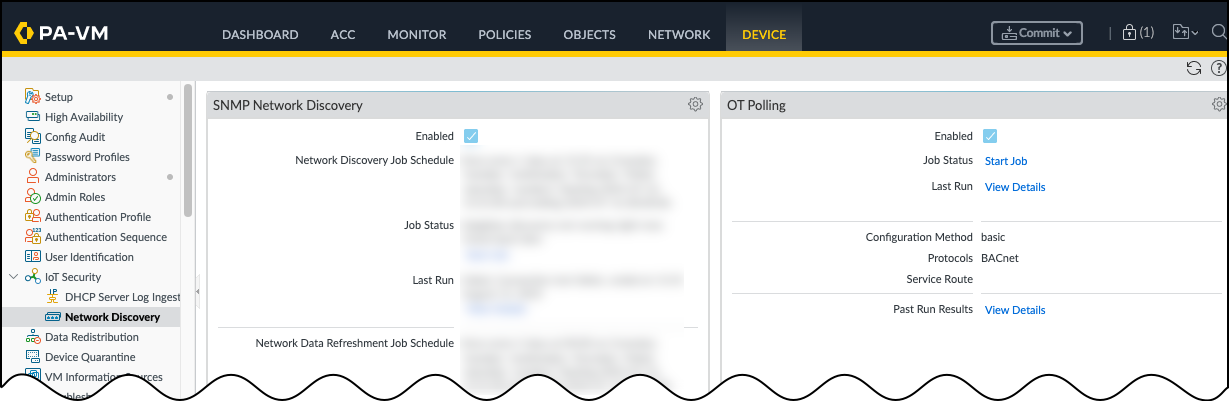
Figure: Enabling OT Polling in the Network Discovery plugin settings.
- Schedule how often the firewall runs a job to poll for devices. In the Schedule Settings tab, you can define how frequently to poll... Specify which days of the week... and whether you only want to poll within a particular date range. The polling schedule uses the firewall's time zone...
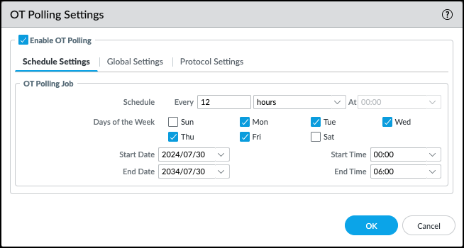
Figure: Configuring the schedule for OT Polling jobs.
-
Configure the
Global Settings
for OT Polling. Click the
Global Settings
tab. Choose your configuration method and which protocols you want to poll...
- Configuration Method : Choose Basic or Advanced. Basic has fixed default ports but modifiable timeout. Advanced allows specifying default ports and timeouts and different IP scopes per protocol.
- Protocol : Choose the protocol you want to use... You must select at least one protocol.
- Optional Service Route : Add any service routes you want to use. By default, the management interface is used.
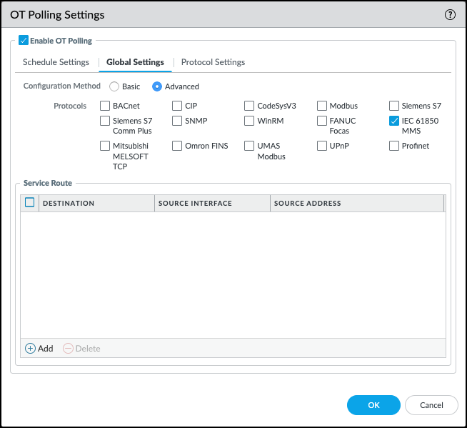
Figure: Configuring global settings for OT Polling, including method and protocols.
-
Configure each protocol that you selected for polling. Click the
Protocol Settings
tab...
- Default Port : (Advanced method only) Enter the port...
- Default Timeout : Enter a default timeout... Basic is preset to 4 seconds. Range 1-300 seconds.
- Default IP Scope : Add a default IP scope... You can specify individual IP addresses, multiple IP addresses, or address groups.
If you specify an IP range or a subnet, the firewall polls every IP address. This can be inefficient and create a lot of unwanted traffic. Network Discovery limits polling to 1,500 IP addresses to manage the amount of traffic introduced and limit the load on the firewall.
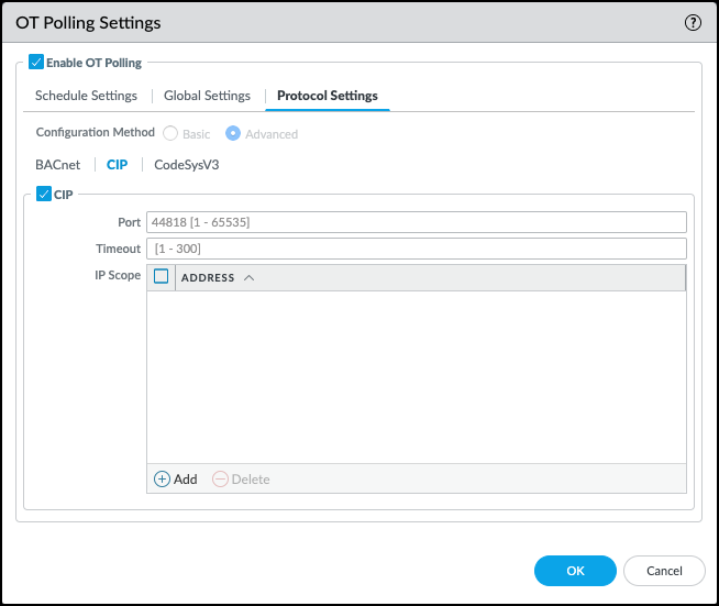
Figure: Configuring specific protocol settings for OT Polling, including IP scope.
- Optional SNMP : When polling with SNMP, choose either SNMP v2 or SNMP v3. (Configuration options for v2/v3 credentials follow)
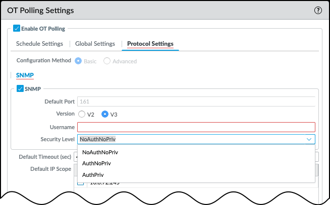
Figure: Configuring SNMP credentials for polling.
- Optional WinRM : When polling with WinRM, enter a WinRM username and password...
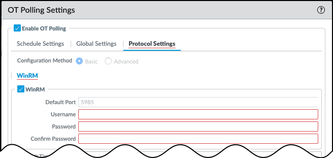
Figure: Configuring WinRM credentials for polling.
- Click OK to save the configured OT Polling settings...
- Click Start Job in the OT Polling section to start the polling job. Even if you defined a polling schedule, you need to start the job after updating the configuration for changes to take effect.
- Optional Review the details of the previous polling jobs by clicking View Details for either the Last Run or the Past Run Results.
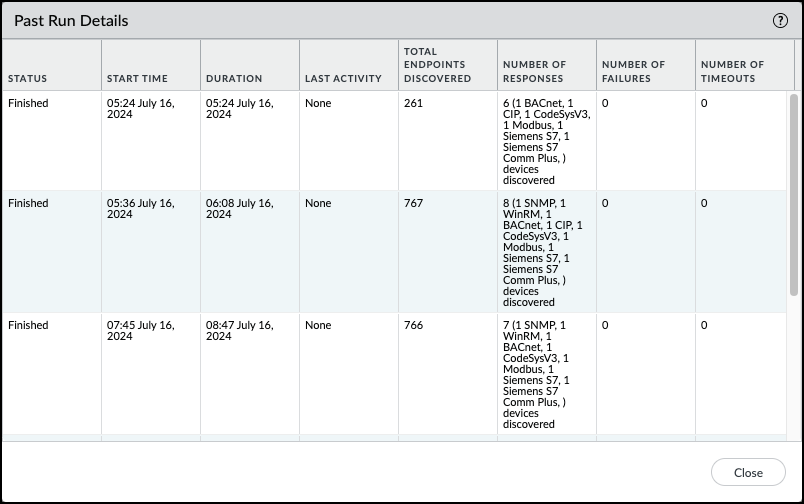
Figure: Viewing details and results of OT Polling jobs.
Use ERSPAN to Send Mirrored Traffic through GRE Tunnels
Unless device traffic is visible to a firewall, the firewall cannot include it in the logs it forwards to IoT Security. When you need to collect data for devices whose traffic doesn't pass through a firewall, mirror their traffic on network switches and use Encapsulated Remote Switched Port Analyzer (ERSPAN) to send it to the firewall through a Generic Routing Encapsulation (GRE) tunnel . After the firewall decapsulates the traffic, it inspects it similar to traffic received on a TAP port. The firewall then creates enhanced application logs (EALs) and traffic, threat, WildFire, URL, data, GTP (when GTP is enabled), SCTP (when SCTP is enabled), tunnel, auth, and decryption logs. It forwards them to the logging service where IoT Security can access and analyze the IoT device data.
You can use this feature for any deployments where traffic from remote switches needs to be inspected. IoT Security is just one use case.
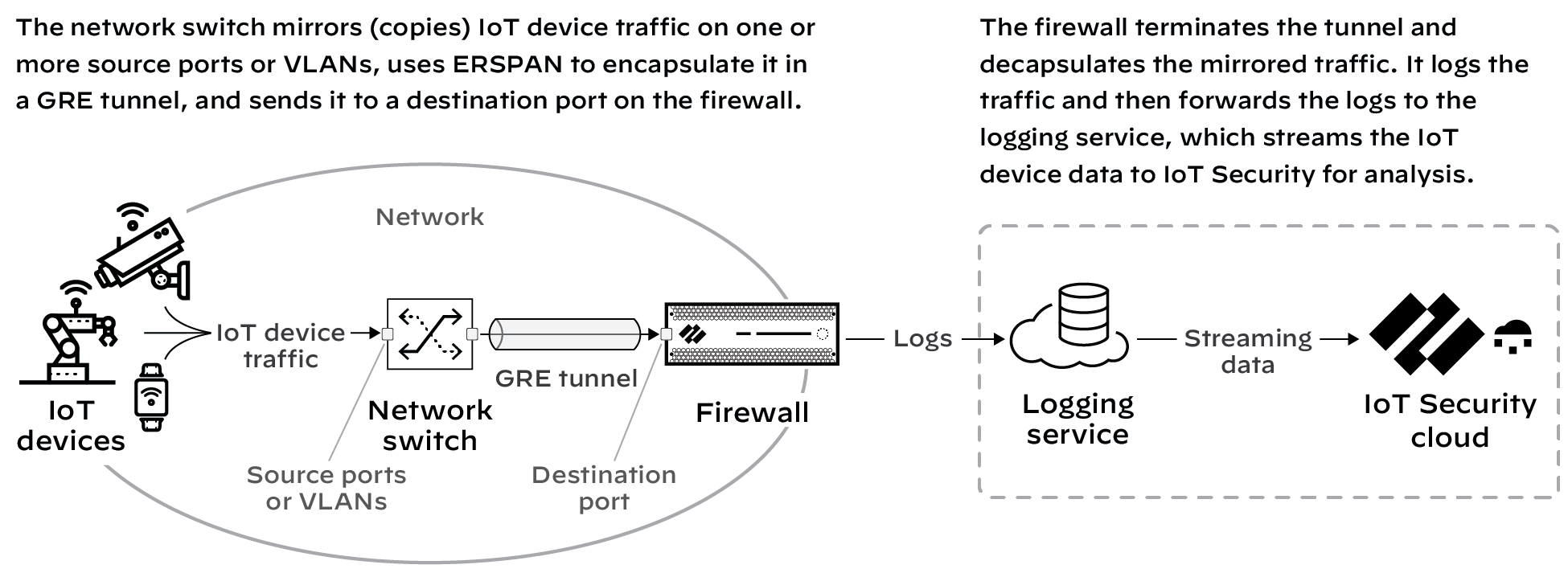
Figure: Using ERSPAN over a GRE tunnel to send mirrored traffic to a firewall for inspection.
This feature requires switches that support ERSPAN such as Catalyst 6500, 7600, Nexus, and ASR 1000 platforms.
Configuration Steps
- Configure a switch that supports ERSPAN to mirror traffic on one or more source ports or VLANs, and forward it through a GRE tunnel to a destination port on a next-generation firewall. For configuration instructions, see the Cisco documentation for your switch.
-
Enable ERSPAN support on the firewall. By default, ERSPAN support is disabled.
- Log in to the firewall and select Device > Session .
- Click the Edit icon for Session Settings, select Enable ERSPAN Support , and then click OK .
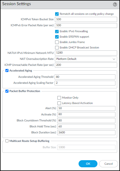
Figure: Enabling ERSPAN Support in PAN-OS Session settings.
The ERSPAN Support check box in the Session Settings section is now selected.
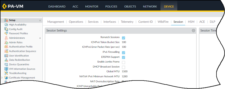
Figure: Session Settings confirming ERSPAN Support is enabled.
- Commit your change.
-
Create a Layer 3 security zone specifically to terminate the GRE tunnel and receive mirrored IoT device traffic...
- Select Network > Zones and then Add a zone.
- Enter the following and leave the other settings at their default values: Name (e.g., ERSPAN-IoT-data), Log Setting (Select IoT Security Default Profile or other log forwarding profile that sends the required types of logs), Type (Layer3).
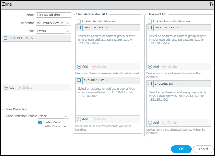
Figure: Configuring a Layer 3 zone for receiving ERSPAN traffic.
- Click OK .
-
Create a Layer 3 interface and bind it to the zone you just created...
- Select Network > Interfaces > Ethernet and then click the Ethernet interface on which you want to terminate the GRE tunnel... Optionally, use a subinterface.
- Enter the following and leave the other settings at their default values: Comment , Interface Type (Layer3), Virtual Router , Security Zone .
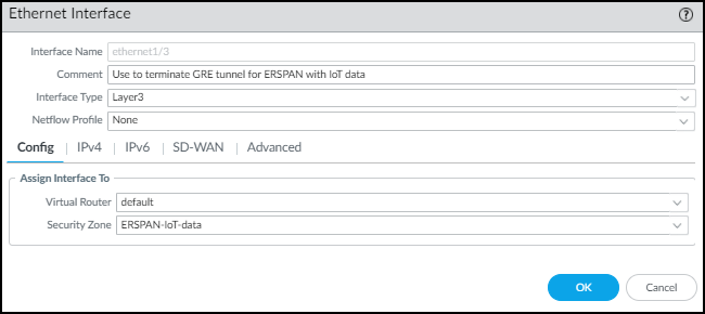
Figure: Configuring a Layer 3 Ethernet interface bound to the ERSPAN zone.
- Click IPv4 , select Static for the address type, and Add an IP address for the interface. The switch uses this in its GRE tunnel configuration as the IP address of its peer.
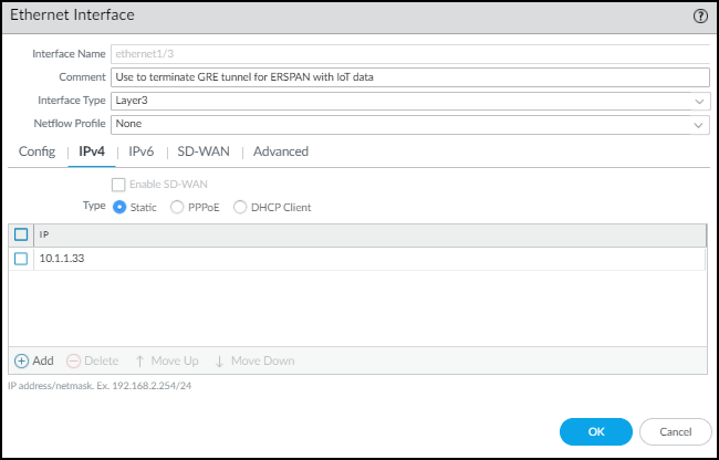
Figure: Adding an IPv4 address to the Layer 3 interface.
- Click Advanced and either add a New Management Profile or select a previously defined profile...
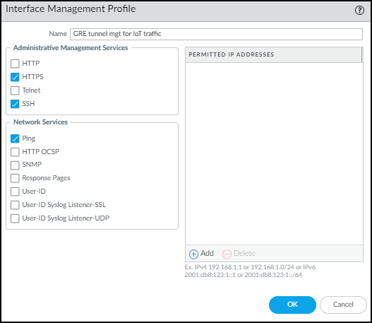
Figure: Configuring the management profile for the Layer 3 interface.
- Click OK to save the new interface management profile and then click OK again to save the Ethernet interface configuration.
-
Create a tunnel interface with an IP address in the same subnet as that of the corresponding tunnel interface on the switch and bind it to the zone you just created.
- Select Network > Interfaces > Tunnel and then Add the logical tunnel interface for the GRE tunnel...
- Enter the following and leave the other settings at their default values: Interface Name , Virtual Router , Security Zone .
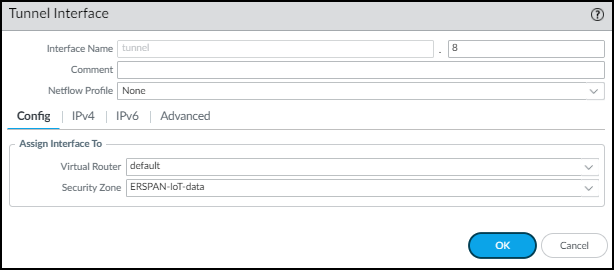
Figure: Configuring a logical Tunnel interface for the GRE tunnel endpoint.
- Click IPv4 and Add an IP address that’s in the same subnet as the IP address of the logical tunnel interface on the switch.
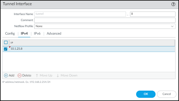
Figure: Adding an IPv4 address to the Tunnel interface.
- Click Advanced and either add a New Management Profile , or select a previously defined profile...
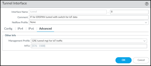
Figure: Configuring the management profile for the Tunnel interface.
- Click OK .
-
Configure static routes for the virtual router (VR) for ERSPAN.
- Select Network > Virtual Routers and then click the virtual router for ERSPAN.
- Click Static Routes and then click + Add .
- Enter the following and leave the other settings at their default values: Name , Destination (e.g., 0.0.0.0/0), Interface (the Layer 3 interface), Next Hop (None).
If you know the subnets beyond the switch, create individual static routes for each of them. Otherwise, use a separate VR for ERSPAN and set a default route.
- Click OK .
-
Configure a GRE tunnel with ERSPAN enabled.
- Select Network > GRE Tunnels and then click + Add .
- Enter the following and leave the other settings at their default values: Name , Interface (Layer 3 interface), Local Address (IP of the Layer 3 interface), Peer Address (IP of the switch egress interface), Tunnel Interface (logical tunnel interface), ERSPAN (select).
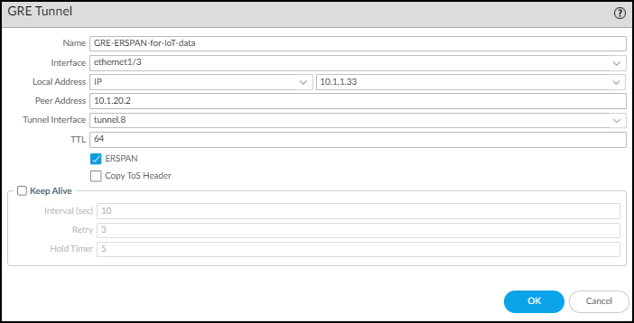
Figure: Configuring a GRE tunnel and enabling ERSPAN.
- Click OK .
The IP addresses of the Ethernet and tunnel interfaces in relation to each other and the rest of the network look like this.
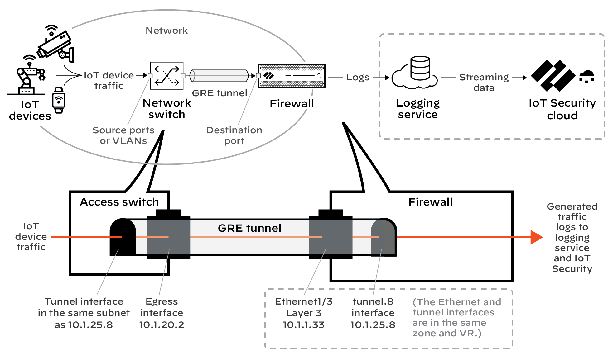
Figure: Relationship between the Layer 3 and Tunnel interface IP addresses for ERSPAN over GRE.
- Commit your changes.
Use DHCP Server Logs to Increase Device Visibility
IoT Security relies on IP address-to-MAC address bindings to ascribe observed network behaviors to IoT devices and uniquely track them... However, in designs where the next-generation firewall is not in the DHCP data path, you can use this method to ingest DHCP server logs and expand DHCP traffic visibility.
In areas of the network where it’s difficult to route DHCP traffic to or through a firewall, configure DHCP servers to send their server logs as syslog messages to the firewall. The firewall then forwards the messages as Enhanced Application Logs (EALs) with a subtype of dhcp-syslog through the logging service to IoT Security. IoT Security parses them to learn the IP address-to-MAC address bindings and add newly learned devices to its inventory. IoT Security also learns device hostnames from the server logs, with the exception of logs from Cisco DHCP servers.
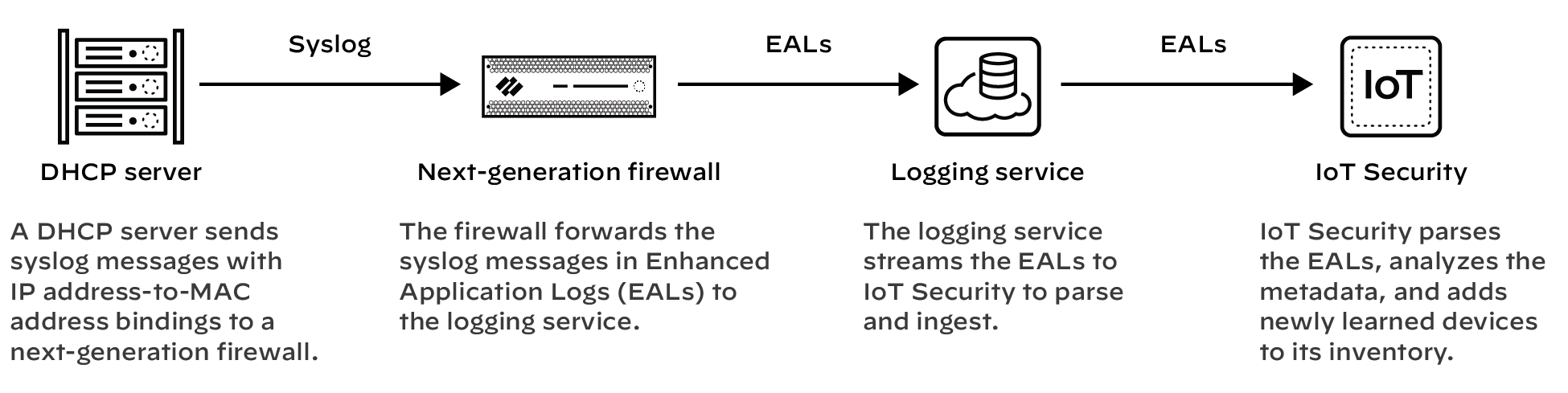
Figure: Flow of DHCP server logs sent as syslog to a firewall for ingestion by IoT Security.
Prerequisites
- A DHCP server with syslog capabilities configured to send messages to a syslog server running on a next-generation firewall
- A next-generation firewall running PAN-OS 11.0 or later with an active IoT Security subscription
DHCP server log ingestion is not available on CN-, M-, and WF-series next-generation firewalls.
Set up the Next-generation Firewall
Set up your next-generation firewall to receive syslog messages from one or more DHCP servers. The firewall will automatically forward the syslog messages it receives as EALs to the logging service, which streams them to IoT Security to parse and analyze.
- Add a DHCP server to the next-generation firewall. Log in... select Device > IoT Security > DHCP Server Log Ingestion > +Add , configure the following, and then click OK :
Name : Enter a name...
Description : Enter a note...
Enabled : Select to enable the firewall to listen for connections...
IP Address : Enter the IP address from which the DHCP server will connect... An FQDN is not allowed.
Protocol : Select TCP , UDP , or SSL . (Notes on characteristics follow).
The firewall listens for DHCP server connections using TCP and UDP on port 10514 and connections using SSL on port 16514.
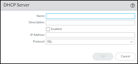
Figure: Configuring a DHCP server source for log ingestion.
- Repeat the previous step to add more DHCP servers. Add more DHCP servers and expand visibility... All next-generation firewalls support a maximum of 100 DHCP servers per firewall.
Set up DHCP Servers for Syslog
Configure your DHCP servers to send syslog messages of their server logs to the management interface on the next-generation firewall. Make sure to configure the DHCP server to use the same protocol configured for it on the firewall: TCP, UDP, or SSL. You can use DHCP servers such as Windows, Linux, Cisco, or Infoblox for example. See the documentation for your DHCP servers for configuration instructions.
Check DHCP Server Connection Status
To see all the configured DHCP servers, select Device > IoT...
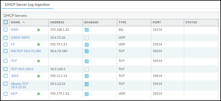
Figure: Viewing the status of configured DHCP servers for log ingestion.
A green circle next to a DHCP server name means it was configured in Panorama and is read-only when viewed in the web interface of the local next-generation firewall.
When a DHCP server using TCP or SSL is currently connected to the firewall, “Connected” appears in the Status column. “Connected” also appears in this column if a DHCP server using UDP has been connected within the past two hours. At all other times, the Status column is empty, indicating that the server isn’t currently connected to the firewall.
The following CLI commands are also useful for checking DHCP server settings, the status of their connections, and the data they’re providing for IoT Security.
| CLI Command | Description |
|---|---|
| show iot dhcp-server status { all | server <server-name> } | Entering all shows a table with all DHCP servers configured and enabled... Entering server <server-name> shows detailed information about a specific DHCP server and its recent activity. |
| show iot eal dhcp-syslog-eal | This command shows information related to EALs carrying DHCP server syslog messages. |
Control Allowed Traffic for Onboarding Devices
When new devices join the network, they must be allowed to function normally so that IoT Security can identify them by analyzing their normal network behavior. However, firewalls are typically configured with Zero Trust security policy rules that allow only the network activities that devices need based on their function. As a result, the rules might inadvertently block traffic for a new device that, if allowed, would have allowed IoT Security to determine its identity.
To overcome this, you can configure one or more onboarding policy rules that use Device-ID to apply the rules only to devices that have been recently detected on the network but have not yet been confidently identified. For the firewall to enforce the rule, a device must be categorized as an Onboarding Device . IoT Security places low-confidence devices in this category during a customizable period of time that starts when IoT Security first detects them on the network. Devices continue to be categorized as “Onboarding Device” until IoT Security confidently identifies them with a confidence score above 90 or until the time period ends. The policy rule does not apply to other, previously identified devices and must be configured to allow new devices enough network access for IoT Security to identify them. Once IoT Security identifies them, it switches them over to an appropriate category for what they are. The firewall can then apply appropriate policy rules based on their identities. If IoT Security cannot confidently identify one or more devices and the time period expires, it still switches them to a category it considers appropriate, but because their confidence scores are below 90, IoT Security doesn’t generate any security rule recommendations.
Configuration Steps
-
Configure a security policy rule that allows certain types of traffic from any device whose Device-ID attribute for Category is “Onboarding Device”.
- Log in to the PAN-OS or Panorama web portal and configure a security policy rule that allows the basic types of traffic that devices in certain VLANs or in different IP address subnets would be expected to generate. For example, a rule for a VLAN that contains printers should allow only typical printer-specific traffic...
- Add a Device-ID component to the rule and specify Onboarding Device as the category that a device must match for the firewall to apply the rule... (In short, Add a security policy rule on Policies > Security . Select the Source tab, click Add in the Source Device section, and then click Device . In the Device Object dialog box that appears, choose Onboarding Device in the Category list.)
- Create additional security policy rules that specify Onboarding Device as the category...
-
Enable the new device onboarding feature based on Device-ID in IoT Security.
- Log in to the IoT Security portal as a user with owner privileges.
- Select Policy Sets > Settings and toggle on Control newly onboarded low-confidence devices through firewall policy rules .
- Optionally change the period of time during which IoT Security categorizes a device as an Onboarding Device... The default onboarding period is 7 days. There are no maximum and minimum limits. You can also switch from a limited period of time to an unlimited length of time.
After you enable this feature and set a length of time for the onboarding period, IoT Security displays a daily system alert if there are any devices for which the onboarding period will soon be expiring. The alert appears a few days before the expiration and includes a link to the Assets > Devices page with a filter applied to show just these devices.
- To see which devices are in the Onboarding Device category, select Assets > Devices and, if necessary, show the Onboarding Device column in the Devices table. If necessary, also show the First Seen column and then sort by this to organize the display...
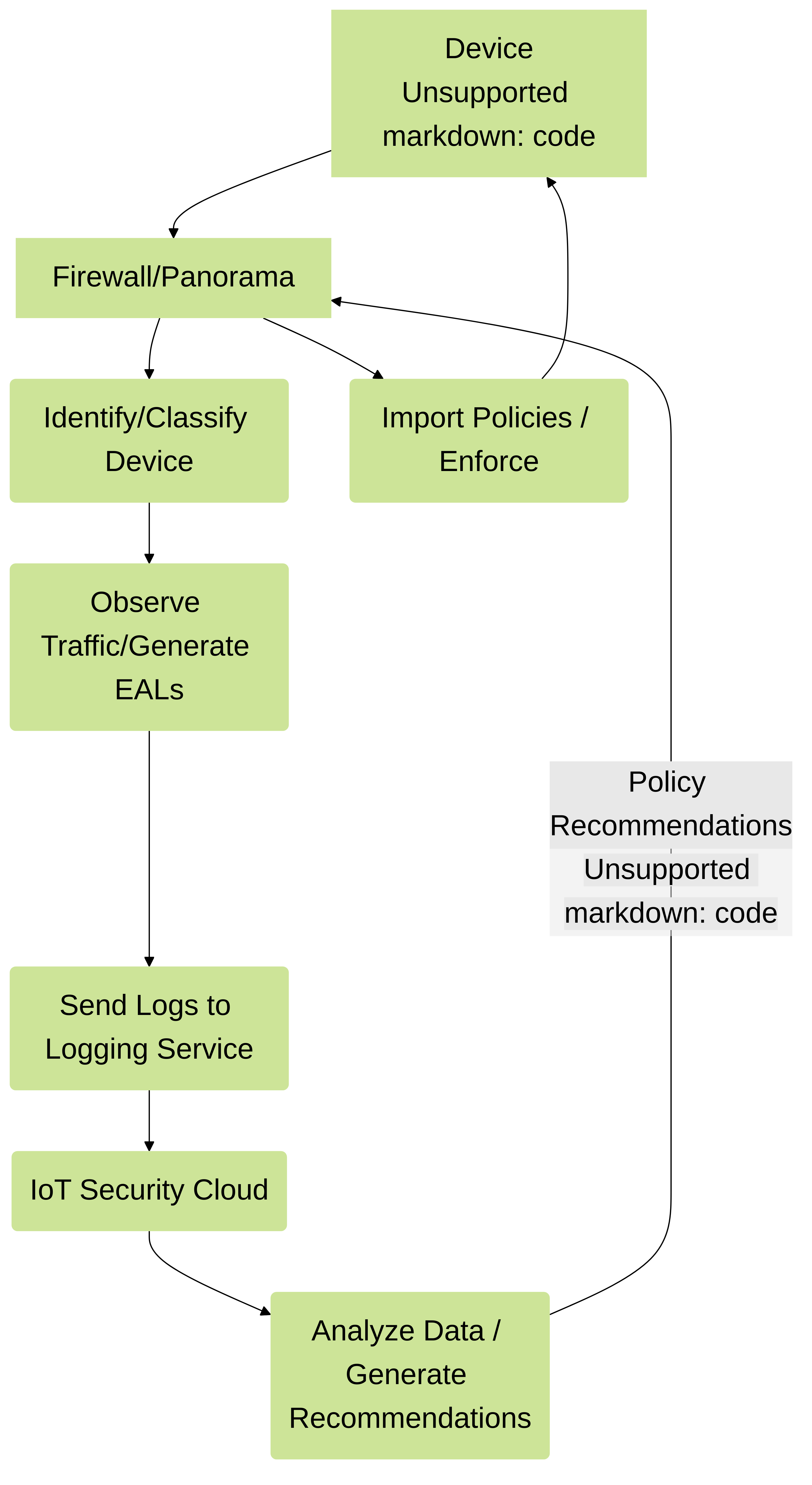
Support Isolated Network Segments
An isolated network segment is a part of a private network that allows an extremely limited set of connections between devices in the segment and devices in any other local segment or in the public network... To accomplish this, you can configure next-generation firewalls as security telemetry gateways (referred to in the PAN-OS web interface as proxies ) to forward traffic logs from the isolated segment through the non-isolated part of the network to the Palo Alto Networks logging service, where IoT Security can access it. In addition, the security telemetry gateways can forward requests from isolated firewalls for the data and files they need to onboard IoT Security and support Device-ID: licenses, certificates, IP address-to-device mappings, security policy rule recommendations, and dictionary file downloads.
This data path occurs only through security telemetry gateways, and only requests and network traffic logs that next-generation firewalls generate, not actual data from protected devices, are sent on this path through the security telemetry gateway chain.
Importantly, there are no direct connections between devices in the isolated network segment and the cloud, and the status of the security telemetry gateway-to-cloud connection (up or down) has no impact on protected device operations nor on next-generation firewall functions such as policy enforcement and threat detection and prevention. All protected device and firewall operations will continue to operate even if an upstream security telemetry connection goes down.
You can use a single security telemetry gateway or a chain of two or more security telemetry gateways for additional security layering... Firewalls in the OT network would send traffic logs to the OT security telemetry gateway, which forwards them to the IT security telemetry gateway, which forwards them to the Palo Alto Networks logging service. Setting up next-generation firewalls in a security telemetry gateway chain like this increases the depth of the logical network segment boundary because the IT security telemetry gateway blocks inbound connections to the OT security telemetry gateway.
The following next-generation firewalls support the security telemetry gateway feature:
- Physical firewalls: PA-1400 series, PA-3400 series, PA-5400 series (except PA-5450)
- VM-300, VM-500, VM-700
The firewalls must be running PAN-OS version 11.0.1-h2 or later.
When deploying firewalls for a network that contains an isolated OT network segment, set up the security telemetry gateways in order from the IT perimeter... toward the deepest part of the OT network: IT security telemetry gateway, then OT security telemetry gateway, and then OT firewalls. By deploying them in this order, you will have the information you need after completing one deployment to deploy the next one...
The following illustration shows the logical relationship of next-generation firewalls in a security telemetry gateway chain and the IP addresses and subnets used as examples... As shown here, OT firewalls initiate all outbound connections through the OT and IT security telemetry gateways to the logging service, IoT Security cloud, and update server.
Figure: Logical architecture of security telemetry gateways in a chain for isolated networks.
Although having an IT security telemetry gateway in front of an OT security telemetry gateway lets you block inbound connections..., multiple cascading gateways is not required. If you use a single security telemetry gateway at the perimeter of the OT network, it becomes the proxy between OT firewalls and Palo Alto Networks cloud services in the external network instead of hopping through an IT security telemetry gateway.
Configure the IT Security Telemetry Gateway
The IT security telemetry gateway is the next-generation firewall that forwards the traffic logs and requests it receives from the OT security telemetry gateway... It would typically be deployed on the network perimeter.
-
Configure a next-generation firewall to act as an IT security telemetry gateway.
- Access the CLI... and enter the following command to enable the firewall to function as a security telemetry gateway (proxy): set system setting paloalto-networks-service-proxy on
- Reboot the firewall.
When using Panorama to manage firewalls, enter the above command in the Panorama CLI and then reboot Panorama.
- Log in to the firewall web interface... and configure two Layer3 interfaces—one on the IT network and the other on the external network. For example, configure ethernet1/1 with IP address 192.168.10.1/24 for the IT network and ethernet1/2 with IP address 1.1.1.1/24 for the external network.
- Create a loopback interface with an IP address in a different subnet... For example, 10.1.2.3.
- Create a virtual router for all three interfaces and add them to it (e.g., vr1 )...
- Create a zone for each interface such as IT , external , and loop .
- Select Network > DNS Proxy and configure a DNS proxy for the interface in the external zone...
- Select Objects > URL Category and create the following URL group:
Name : Give the URL list a name; for example, iot_cloud_traffic .
URL List : Add the following URLs (and IP address) to the URL list. These are the only destinations that proxied traffic must be allowed to access.
- *.paloaltonetworks.com/
- *.panservicetest.com/
- ocsp.godaddy.com/
- certificates.godaddy.com/
- *.gpcloudservice.com/
- *.lencr.org/
- 34.122.191.141
When using Panorama to manage firewalls, create the URL category as “shared”.
- Select Policies > Security , and create a universal policy rule that allows any application from the IT zone to the external zone for destinations in the iot_cloud_traffic URL category and position it above other policy rules.
- Select Policies > NAT , and create a policy that translates source addresses of devices and interfaces in the IT and loop zones to the IP address of the egress interface in the external zone. In our example, this would be 1.1.1.1, which is the IP address of ethernet1/2.
- Select Network > Proxy , click the settings icon for Proxy Enablement, choose Palo Alto Networks Service Proxy and then click OK .
- Click the settings icon for Palo Alto Networks Service Proxy Configuration and enter the following:
Connect Timeout : 5 (default)
Listening : Enter the name of the IT network interface; for example, ethernet1/1 .
Upstream interface : loopback.1
Proxy IP : Enter the IP address of the interface in the IT zone; for example, 192.168.10.1 .
DNS-Proxy : Enter the name of the DNS proxy you defined previously; for example, dns-proxy .
Allowed URL Category : Enter the name of the allowed URL group you defined previously, for example, iot_cloud_traffic .
Next Hop Proxy Server : Leave empty.
Next Hop Proxy Port : Leave empty.
- Optional To use IoT Security for device identification, risk assessment, and vulnerability detection in the IT network, subscribe the firewall acting as the IT security telemetry gateway to IoT Security. (Steps for onboarding, licensing, and configuring for Device-ID follow - similar to section-prepare-firewall)
Configure the OT Security Telemetry Gateway
With the IT security telemetry gateway configured and in place, you can next configure the OT security telemetry gateway... It would typically be deployed on the edge of the OT network.
-
Configure a next-generation firewall to act as an OT security telemetry gateway.
- Access the CLI... and enter the following command to enable the firewall to function as a security telemetry gateway (referred to as a proxy in PAN-OS): set system setting paloalto-networks-service-proxy on
- Reboot the firewall.
When using Panorama to manage firewalls, enter the above command in the Panorama CLI and then reboot Panorama.
- Configure two Layer3 interfaces—one on the OT network and the other on the IT network. For example, configure ethernet1/1 with IP address 192.168.100.1 for the OT network and ethernet1/2 with IP address 192.168.10.2 for the IT network.
- Create a loopback interface with an IP address in a different subnet... For example, 10.2.3.4.
- Create a virtual router for all three interfaces and add them to it (e.g., vr1 ) and add a default route using ethernet1/2 as the egress interface and 192.168.10.1, the IP address of ethernet1/1 on the IT security telemetry gateway interface, as the next hop.
- Create a zone for each interface such as OT , IT , and loop .
- If the next hop security telemetry gateway server is a hostname, select Network > DNS Proxy and configure a DNS proxy for the interface of the OT security telemetry gateway that’s in the IT zone... If the next hop security telemetry gateway server is an IP address, you don’t need to configure a DNS proxy and can skip this step.
- Select Objects > URL Category and create the following URL group (same URL list as IT Gateway): Name (e.g., iot_cloud_traffic), URL List (Add the required cloud service URLs).
When using Panorama to manage firewalls, create the URL category as “shared”.
- Select Policies > Security , and create a universal policy rule that allows any application from the OT zone to the IT zone for destinations in the iot_cloud_traffic URL category and position it above other policy rules. Add security policy rules that deny all other outbound connections from the OT network and all inbound connections to the OT network and position them below the rule that allows outbound connections to the destinations in the iot_cloud_traffic URL list.
- Select Network > Proxy , click the settings icon for Proxy Enablement, choose Palo Alto Networks Service Proxy and then click OK .
- Click the settings icon for Palo Alto Networks Service Proxy Configuration and enter the following:
Connect Timeout : 5 (default)
Listening : Enter the name of the 0T network interface; for example, ethernet1/1 .
Upstream interface : loopback.1
Proxy IP : Enter the IP address of the interface in the OT zone; for example, 192.168.100.1 .
DNS-Proxy : Enter the name of the DNS proxy you defined previously; for example, dns-proxy .
Allowed URL Category : Enter the name of the allowed URL group you defined previously, for example, iot_cloud_traffic .
Next Hop Proxy Server : Enter the IP address of ethernet1/1 on the IT security telemetry gateway interface; 192.168.10.1 in our example.
Next Hop Proxy Port : 8080
- Optional To forward network traffic logs for the OT network from the OT security telemetry gateway as well as from OT firewalls, subscribe the OT security telemetry gateway to IoT Security. (Steps for onboarding, licensing, and configuring for Device-ID follow - similar to section-prepare-firewall)
Configure OT Firewalls
With both the IT and OT security telemetry gateways configured, you can set up the OT firewalls to use the security telemetry gateway chain to access the Palo Alto Networks cloud services necessary to support IoT Security:
- Logging service – OT firewalls forward EAL and traffic logs to the logging service...
- IoT Security – OT firewalls retrieve IP address-to-device mappings...
- Update server – OT firewalls periodically download device dictionary files...
- License server – OT firewalls download activated logging service and IoT Security licenses...
- Certificate server – Firewalls fetch new device certificates...
- Customer Service Portal and the hub – Firewalls connect to the Customer Service Portal... and then to the hub...
-
Configure a next-generation firewall to act as an OT firewall.
- Select Device > Setup > Interfaces > Management , configure MGT interface with an IP address on the OT network, and enter the IP address of the OT security telemetry gateway interface in the OT zone as its default gateway; for example: IP Type (Static), IP Address (192.168.100.2), Netmask (255.255.255.0), Default Gateway (192.168.100.1).
The OT firewall uses the management interface to onboard IoT Security and fetch certificates and licenses, forward various traffic logs to the logging service, request IP address-to-device mappings and policy rule recommendations from IoT Security, and download dictionary files from the update server. You can also configure the OT firewall to use one of its Ethernet interfaces... If you do, you must configure service routes...
- Configure interfaces, security zones, and security policy rules as necessary to collect network traffic metadata... PAN-OS provides various options... for example:
Virtual wire to capture OT traffic – Create a virtual wire zone... Add either an intrazone or universal policy rule that allows traffic... and enable logging and log forwarding... Consider placing one or more OT firewalls... at one of the OT Purdue levels (0-3) to capture network traffic... and forward traffic logs to the OT security telemetry gateway.
Tap interface to collect traffic from downstream switches – Create a tap zone with a tap interface to receive traffic from a mirror port... This will capture traffic at other Purdue levels... which can then forward it to the logging service.
Layer 3 interface to collect traffic from a ERSPAN port on downstream switches – Create a Layer 3 zone with a Layer 3 interface... Configure your switches to use Encapsulated Remote Switched Port Analyzer (ERSPAN) to send mirrored traffic through a Generic Routing Encapsulation (GRE) tunnel to the IP address of the OT network interface on the OT security telemetry gateway... After decapsulating the traffic, the OT security telemetry gateway generates various traffic types of logs and forwards them to the IT security telemetry gateway, which then forwards them to the logging service where IoT Security can access them for analysis.
- Select Device > Setup > Services , enter the following settings in the Proxy Server section and leave the other settings with their default values:
Proxy Server:
- Server : Enter the IP address of the OT security telemetry gateway interface in the OT zone; for example, 192.168.100.1...
- Port : 8080
- Use proxy to send logs to Strata Logging Service : (select)
- Select Policies > Security , and create a universal policy rule that allows the following applications from OT network zones to any zones and position it above other policy rules:
google-base
paloalto-device-telemetry
paloalto-iot-security
paloalto-logging-service
paloalto-shared-services
- Subscribe the OT firewall to IoT Security. (Steps for onboarding, licensing, and configuring for Device-ID follow - similar to section-prepare-firewall)
Manage IoT Security Users
Role-based access control (RBAC) enables you to assign privileges and access rights to administrative users through role assignment. You create user accounts in the Customer Support Portal (CSP), assign them roles in the hub, and limit the data they can access by site in the IoT Security portal. For step-by-step instructions about creating users for IoT Security, see Create IoT Security Users documentation.
IoT Security supports the following user roles:
- App Administrator
- Instance Administrator
- Owner
- Administrator
- Read only
The App Administrator and Instance Administrator are common roles... For IoT Security, they provide the same privileges as Owner. To learn more about them, see Available Roles documentation.
The three user roles specifically for the IoT Security portal are Owner, Administrator, and Read only.
| User Role | Role Definition | Access Control |
|---|---|---|
|
Owner
(Also App Administrator and Instance Administrator) |
Access to all functions in the IoT Security portal |
All read/write privileges as administrators plus:
|
| Administrator | Access to most functions in the IoT Security portal |
Create, edit, and delete IoT Security configurations and manage their own account preferences:
|
| Read only | Can only view data in the IoT Security portal |
|
For Panorama-managed Prisma Access tenants with an IoT Security add-on license, add the following types of users to give them access privileges to both Prisma Access and IoT Security:
| Prisma SASE Platform User Roles | IoT Security User Roles |
|---|---|
| Superuser, MSP Superuser | Owner |
| N.A. | Administrator* |
| View Only Administrator | Read-only |
* There is no user role in Prisma SASE that maps to the Administrator role in IoT Security.
For new Panorama-managed Prisma Access customers as of August 2022... or an existing Panorama-managed Prisma Access customer whose Prisma Access instance has been transitioned to the Prisma SASE platform, use Common Services: Identity & Access for managing user access, roles, and service accounts.
For existing Panorama-managed Prisma Access customers whose Prisma Access instance has not yet been transitioned..., you can continue using the existing process to create administrative users until the transition completes.
Create IoT Security Users
When users log in to the IoT Security portal using single sign-on (SSO), they go through a two-step process. In step 1, an SSO identity provider (IdP) authenticates users by verifying their credentials. In step 2, users are authorized and provided with a role to access IoT Security.
When users log in... using Palo Alto Networks SSO , their credentials are verified against user accounts in the Customer Service Portal (CSP). Then their user role is assigned according to the Identity & Access section of the hub. User roles determine what they can see and do in the portal. These user roles are referred to as “externally managed user roles” in contrast to “internally managed user roles”...
In addition, IoT Security also provides an option to verify users against an Active Directory (AD) authentication system through SSO . In this case, user accounts are in Active Directory, which verifies user credentials on behalf of IoT Security. You can manage the role of a given user in two different ways... managed internally by IoT Security or managed externally by Active Directory.
External roles are managed in the AD instead of the hub as done in the Palo Alto Networks SSO option.
Because the user role can be managed in two different places, when users log in through an SSO, IoT Security might find their external roles are different from their internal roles. In such cases, whichever role is higher takes precedence.
Authenticate Users with the Palo Alto Networks SSO and Manage User Roles in the Hub
IoT Security supports role-based access control (RBAC) through App Administrator, Instance Administrator, Owner, Administrator, and Read-only roles. Creating users for the IoT Security application involves three steps:
- Create a user account in the Customer Support Portal
- Assign a user role in the hub
- (For Administrator and Read-only users) Allow access to all sites or a subset of sites
- Log in to the Customer Support Portal with superuser permissions...
- Click Members > Create New User , enter the required information, and then Submit . A new user account is created... An email notification is sent to the new user with login credentials.
- Log in to the hub.
- Click the gear icon... and then Access Management .
- Expand the IoT Security section..., select the IoT Security instance..., select the check box for the user account..., and then Assign Roles .
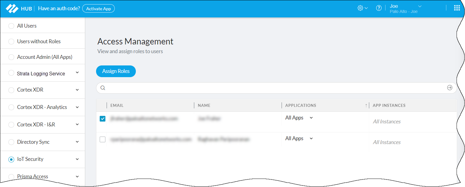
Figure: Assigning roles to a user for an IoT Security instance in the hub.
- Select IoT Security in the left panel to display the IoT Security role assignment window...
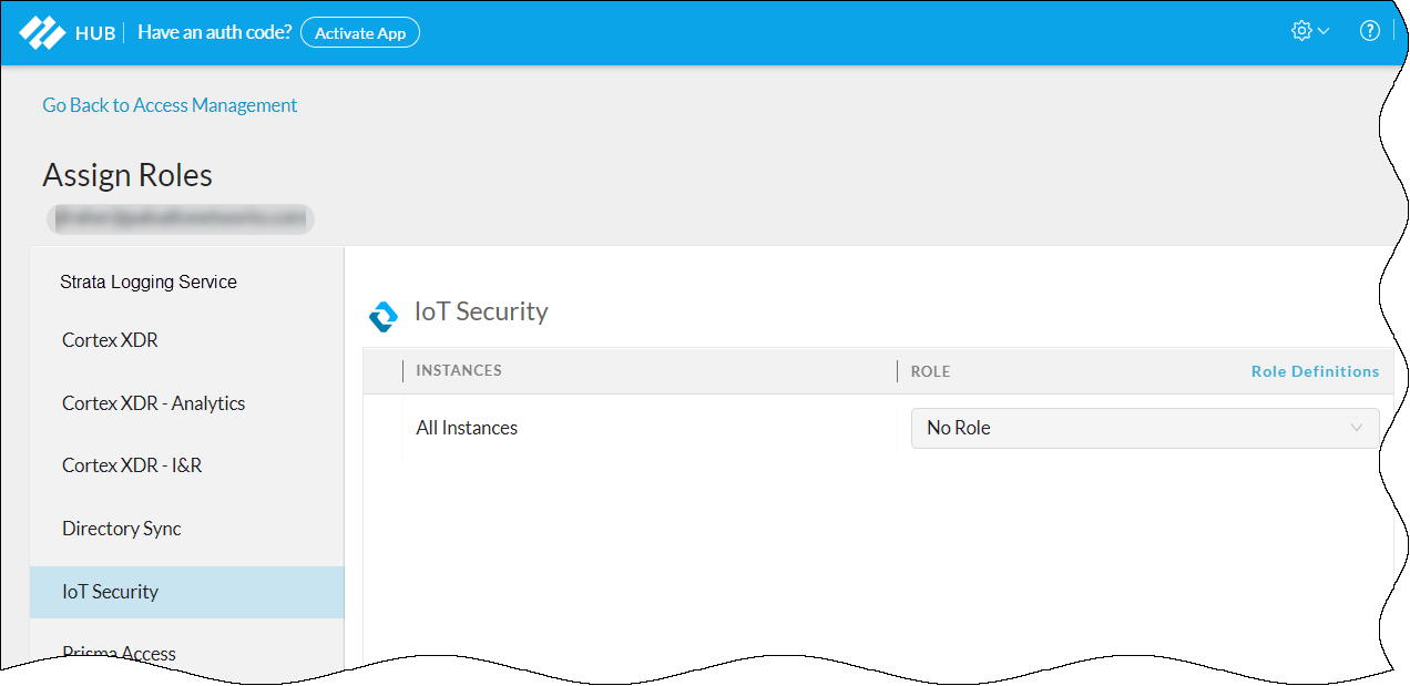
Figure: Selecting an IoT Security specific role for the user.
- Choose one of the following roles from the Role drop-down list: App Administrator, Instance Administrator, Owner, Administrator, Read only.
- For information about these user roles, click Role Definitions . To learn more about the App Administrator and Instance Administrator roles..., see Available Roles documentation. To learn more about the Owner, Administrator, and Read only roles, which are specific to IoT Security, see Manage IoT Security Users documentation.
Authenticate Users with an Active Directory SSO and Manage User Roles in Active Directory
-
Prepare the authentication system. Before you configure IoT Security, prepare your Active Directory to communicate with it and export the identity provider (IdP) metadata file that IoT Security will need to communicate with the IdP.
-
Configure your IdP with the following URLs, replacing the
tenant-id
variable with your own tenant ID, which is the first part of your IoT Security portal URL:
https://tenant-id.iot.paloaltonetworks.com/login
Depending on how you configure your IdP, either point it to the IoT Security metadata URL to retrieve all the necessary data or enter the information separately.
- Assertion Consumer Service (ACS) – This is the destination... https://tenant-id.iot.paloaltonetworks.com/v0.3/zauth/saml2_sso/acs
- Entity ID – This is the URL that uniquely identifies the Zingbox SP. https://tenant-id.iot.paloaltonetworks.com/v0.3/zauth/saml2_sso/metadata
- Palo Alto Networks Metadata – This file includes the ACS URL and entity ID plus other parameters... https://tenant-id.iot.paloaltonetworks.com/v0.3/zauth/saml2_sso/metadata
-
Configure your IdP with the following URLs, replacing the
tenant-id
variable with your own tenant ID, which is the first part of your IoT Security portal URL:
https://tenant-id.iot.paloaltonetworks.com/login
Depending on how you configure your IdP, either point it to the IoT Security metadata URL to retrieve all the necessary data or enter the information separately.
To see the URLs with your specific tenant ID, follow steps 1-2 in the next section and then copy the URLs in the Service Provider (SP) Configuration Details section.
- Either copy and save the URL where IoT Security can import the IdP metadata file... or download the file...
-
Prepare IoT Security to use an externally managed SSO.
- Log in to the IoT Security portal as an owner, navigate to Administration > User Accounts , and then Manage SSO . Palo Alto Networks is the default SSO...
- To add a user-configured SSO, Add New SSO , and then enter the following...: Name (Up to 16 characters), Logo (Optional) (Up to 2 MB, .bmp, .jpg, or .png), IdP Metadata (URL or uploaded file).
- Validate the IdP metadata URL or uploaded file. Validating the IdP metadata URL activates the Save and Test buttons.
- Configure the following fields to map attributes to IoT Security user roles. Map an SAML fully qualified claim name to the user attribute. (Attributes for First Name, Last Name, Phone Number follow)
-
Configure the following settings to identify AD user groups whose users you want Active Directory to authorize. If you leave them empty, IoT Security authorizes them locally.
- Attribute to get AD Groups : Enter the attribute in the SAML 2.0 response...
- AD Group Format : Select whether the attribute is formatted as Plain Text or Regular Expression . These are how IoT Security maps AD user groups to IoT Security user roles...
- AD Group and User Role : Enter an Active Directory group name and then choose the IoT Security user role to map it to: Owner , Administrator , or Read Only . Click + to add more AD group-to-user role mappings. You can create up to 50 mappings. A single AD group cannot map to multiple IoT Security user roles, but multiple AD groups can map to the same IoT Security user role.
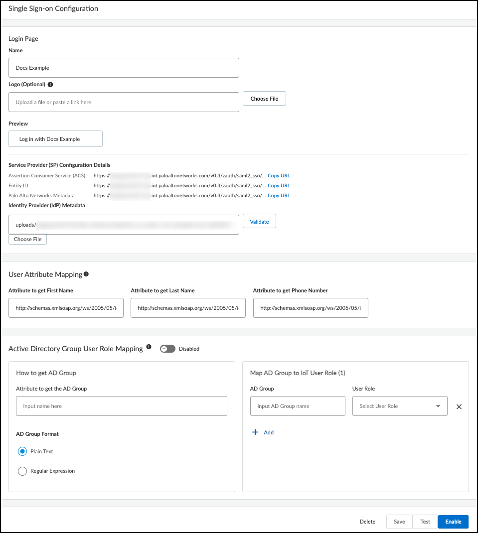
Figure: Mapping Active Directory groups to IoT Security user roles in the SSO configuration.
For information about the IoT Security user roles, see Manage IoT Security Users documentation.
- Save the SSO configuration.
- Test the SSO configuration. IoT Security opens a small window to log in using the authentication system.
- When done with the test, click Confirm .
- Enable the SSO configuration.
- After enabling the configuration, the Enable button changes to Disable and Edit .
Authenticate Users with any SSO and Manage User Roles in the IoT Security Portal
User roles are set for user accounts in external SSO authentication systems... but you can also log in to the IoT Security portal with owner privileges and set other roles for administrators and read-only users. If the externally and internally managed roles are different, IoT Security assigns the higher of the two. Therefore, only set user roles internally on IoT Security that are higher than those set externally; otherwise, an internal role will never be assigned. The ranking of roles from highest to lowest is owner, administrator, read-only user.
If user accounts in an external SSO don't have any externally managed roles defined, these users won't be able to log in to IoT Security until a local user with owner privileges sets internally managed roles for them and invites them to log in to IoT Security.
-
Invite users who have an account on an external SSO but no externally managed role to access IoT Security. Skip this step if users have an externally managed role that maps to a role in IoT Security.
- Log in to IoT Security as a user with owner privileges, select Administration > User Accounts and then click the Invite New User icon ( + ) above the User Accounts table.
- Enter an email address, choose a role ( Owner , Administrator , or Read only ), specify which sites the user can access, and then Invite .
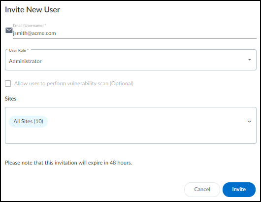
Figure: Inviting a new user to the IoT Security portal and assigning their initial role and site access.
IoT Security automatically generates an email with a login link and sends it to the user. The invitation is valid for 48 hours after it's sent.
When the email recipient clicks a link..., he or she is directed to the login page. The user clicks the Log in with <sso-name> button to log in through SSO. After the user logs in, IoT Security grants him or her access with the local role you specified.
- If you want to invite more users, repeat the previous steps for each one.
- View users, their externally managed roles, role providers, and internally managed roles and which sites they can access. You can see a list of users and their roles on the Access Management page in the hub and, if you’re logged in with owner privileges, on the User Accounts page ( Administration > User Accounts ) in the IoT Security portal.
Externally Managed Role and Role Provider : If IoT Security applies the user role that’s set on the external SSO..., the role appears... and the SSO name appears... If IoT Security has an internally managed role for a user that’s the same as or higher than his or her externally managed role, it applies the internally managed role. In this case, these two columns are empty.
Internally Managed Role : This column lists user roles defined in IoT Security. It’s only empty if there isn’t a role defined internally.
After you create a user account in the Customer Support Portal and hub, the account won't appear on the Administration > User Accounts page in the IoT Security portal until the user logs in to the IoT Security portal.
-
Assign a user with an internally managed role.
- When logged in to the IoT Security portal with owner privileges, click Administration > User Accounts and then click an entry for an administrator or read-only user in the Email (Username) column. The User Role & Access dialog box opens.
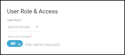
Figure: User Role & Access dialog for modifying an existing user's internal role and site access.
- Choose a different role from the User Role drop-down list. When there are different externally and internally managed roles for the same user, IoT Security applies the role with higher privileges. Therefore, when setting an internal role, choose one that is higher than the one assigned by an external SSO authentication system.
- Determine which sites an administrator or read-only user can access. By default, all users have access to all sites. To give the user access to a subset of sites, click the x in the All label and then select the names of the sites or site groups to which you want to permit access.
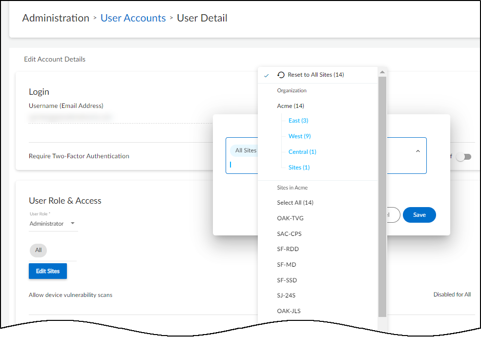
Figure: Controlling a user's access to specific sites or site groups.
For information about site groups and how to use them to control what data users can access, see Sites and Site Groups documentation.
- When done, Save the configuration change. The next time the user logs in, he or she will only have the privileges of the internally managed role and access to devices and data for the selected sites.
Offboard IoT Security Subscriptions
There are three ways to offboard IoT Security services from a firewall:
- Deactivate the IoT Security license on a firewall and optionally transfer it to another firewall
- Transfer a firewall from one customer support portal (CSP) account to another
- Let the subscription expire
Deactivate Firewalls and Transfer Licenses
If you want to remove an IoT Security license from a firewall—and perhaps then use the license on another firewall—you can do so on the Customer Support Portal.
- Log in to your Customer Support Portal account.
-
Disassociate IoT Security licenses from one or more firewalls.
- Select License Management > Activated Licenses , select the license-to-firewall associations that you want to sever based on firewall serial numbers, and then Deactivate Licenses .
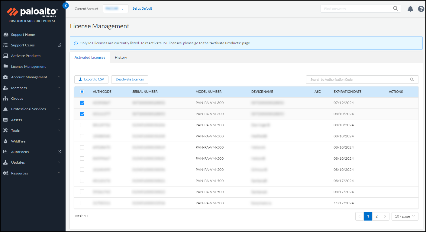
Figure: Deactivating activated licenses in the Customer Support Portal.
- Confirm the deactivation.
If you want to apply the deactivated licenses to other firewalls and you have multiple IoT Security license purchase orders, note the number of available licenses in the orders on the Activate Products page before confirming the deactivation. Then when you return to this page after deactivating licenses, you can tell which order they were returned to because the license number will have increased.
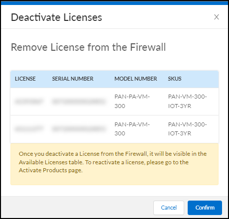
Figure: Observing the return of deactivated licenses to the available pool in a purchase order.
This dissociates the selected IoT Security licenses from the firewall serial numbers and returns them to the pool of available licenses in the original order on the Activate Products page.
- Verify that the Hub also shows that the IoT Security licenses disassociated from the firewalls. Both the IoT Security license and the firewall need to be disassociated on the Hub. If the IoT Security license and the firewalls still show as associated on the Hub, reach out to Palo Alto Networks support.
-
Associate licenses with other firewalls or reassociate them with the same firewalls.
- Select Activate Products > Ready for Activation and then click Activate Now for the order with licenses to activate.
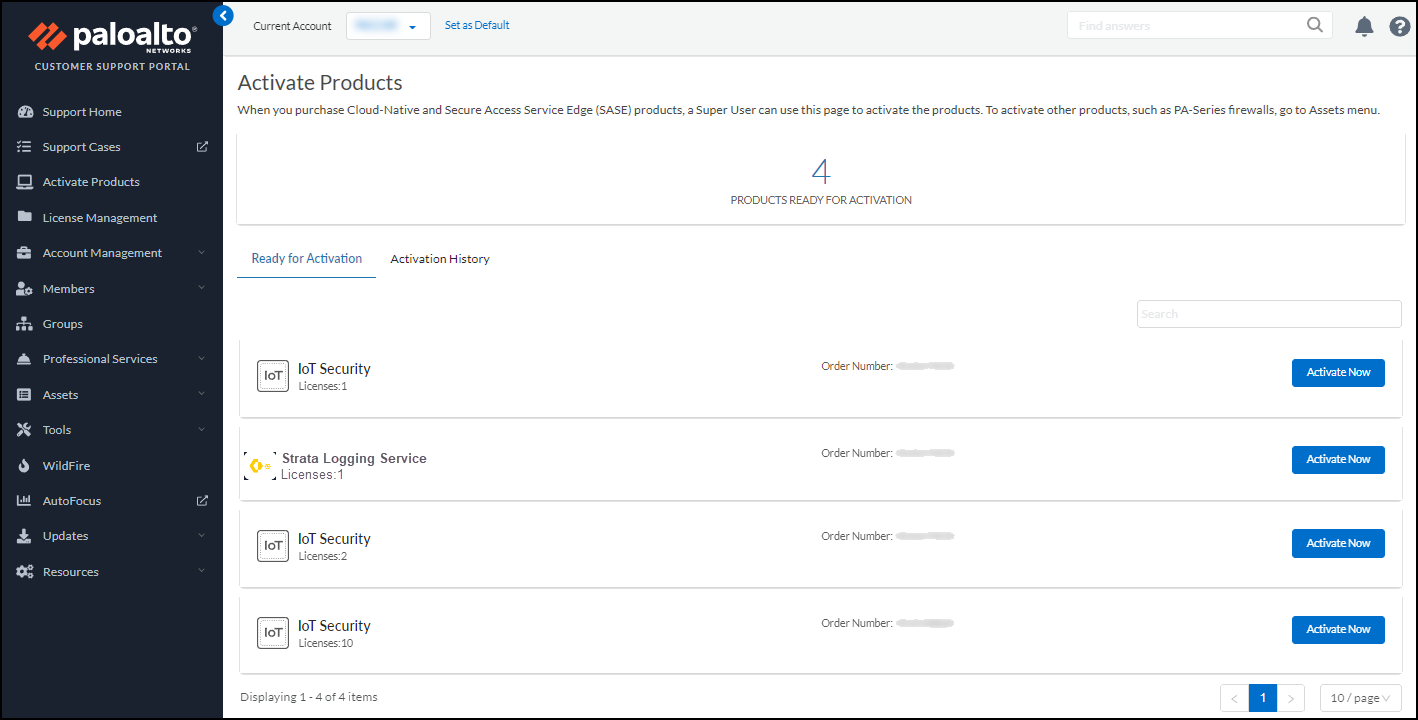
Figure: Ready for Activation section in the hub showing licenses available for activation.
- Follow the workflow described in Onboard IoT Security documentation. When you reach the point in the onboarding workflow when you select firewalls to subscribe to IoT Security, you can see the length of time remaining for each license in the Purchased Term drop-down list. If you want to apply the same license that you just deactivated to another firewall, you’ll notice that its remaining length of unused time will be shorter than other licenses that haven’t yet been put in service...
Transfer Firewalls between CSP Accounts
If you have two CSP accounts or are an MSSP managing multiple accounts, you can transfer a firewall from one account to another... When you transfer the firewall, all its licenses are transferred along with it. To do this, log in to the CSP and click Devices . Find the device..., click its serial number..., and then click Transfer Ownership . In the Device Transfer dialog box..., enter the destination email address of the owner of the account to which you’re transferring the firewall.
Let the IoT Security Subscription Expire
When a firewall no longer has an IoT Security subscription because it expired (and there is no pending license renewal), IoT Security services for that firewall stop and the connection between IoT Security and the firewall is terminated. IoT Security unsubscribes from the firewall log feed. As a result, it stops receiving and processing logs from that firewall. The firewall stops receiving new policy recommendations and IP address-to-device mappings, and it clears its cached mappings after 200 minutes (about three hours). At that point, none of the device-based policy rules using Device-ID will work and should be removed from your policy set. An efficient way to remove them is to check the Source Device and Destination Device columns on the Policies > Security page and remove all rules that have entries in either of these two columns.
IoT Security Integrations with Third-party Products
After IoT Security identifies IoT devices on your network and discovers if they pose any security threats, it works with next-generation firewalls—and also with Prisma Access—to protect your devices and network. In addition, you can integrate IoT Security with third-party products to expand the use of their specific features to include IoT. For example, when a network access control (NAC) solution integrates with IoT Security, it can allow or deny network access to IoT devices whose identity it would otherwise be unaware of... Sometimes an integration works in one direction with IoT Security sharing its device information with a third-party product, and sometimes it works the other way with IoT Security learning device information from a third-party product. Other integrations enhance IoT Security functionality, such as its integration with third-party vulnerability scanners.
There are two options for integrating IoT Security with third-party systems and a third option for integrating Cortex XSOAR with IoT Security through its API:
- IoT Security public cloud with a cohosted, limited-featured Cortex XSOAR instance (requires the purchase of an IoT Security Third-party Integrations Add-on, which comes with an automatically generated, cohosted XSOAR instance at no extra charge). An IoT Security third-party integrations add-on does not require the purchase of a full Cortex XSOAR product. After you enable the add-on, IoT Security automatically generates a cloud-hosted XSOAR instance with limited functionality...
- IoT Security with an on-premises, full-featured Cortex XSOAR server
- Full-featured Cortex XSOAR instance with access to the IoT Security API
For information about the third-party integrations that IoT Security supports, see the IoT Security Integration Guide documentation.
IoT Security Integration with Prisma Access
Prisma Access uses a cloud-based infrastructure that lets you avoid the challenges of sizing firewalls and computing resource allocation while securing remote networks and mobile users. To identify IT and IoT devices at your remote sites, detect IoT device vulnerabilities, and discover threats posed to these devices and the network, Prisma Access can integrate with IoT Security through a purchased add-on. In addition, IoT Security also provides Prisma Access with policy rule recommendations through Panorama to permit only acceptable network behavior and block anomalous behavior from your IoT devices.
For IoT Security to identify IT and IoT devices, and analyze risk levels and detect security alerts on IoT devices, it must be able to access network traffic metadata. The more data it has to work with, the more accurate and faster it can be. Therefore, it's critical to do two things to collect as much traffic metadata as possible. First, design your network strategically so that Prisma Access sees all traffic from your remote sites, including DHCP traffic. Then apply policy rules to as much traffic as you can and enable logging and log forwarding on these rules to send traffic metadata to Strata Logging Service.
DHCP traffic is particularly important to IoT Security. It provides IoT Security with useful data, including a mapping of the IP address to MAC address of each DHCP client... To obtain this data, ensure that a DHCP server is in your data center or in a similar centralized site and a DHCP relay agent is on the customer premises equipment (CPE)...
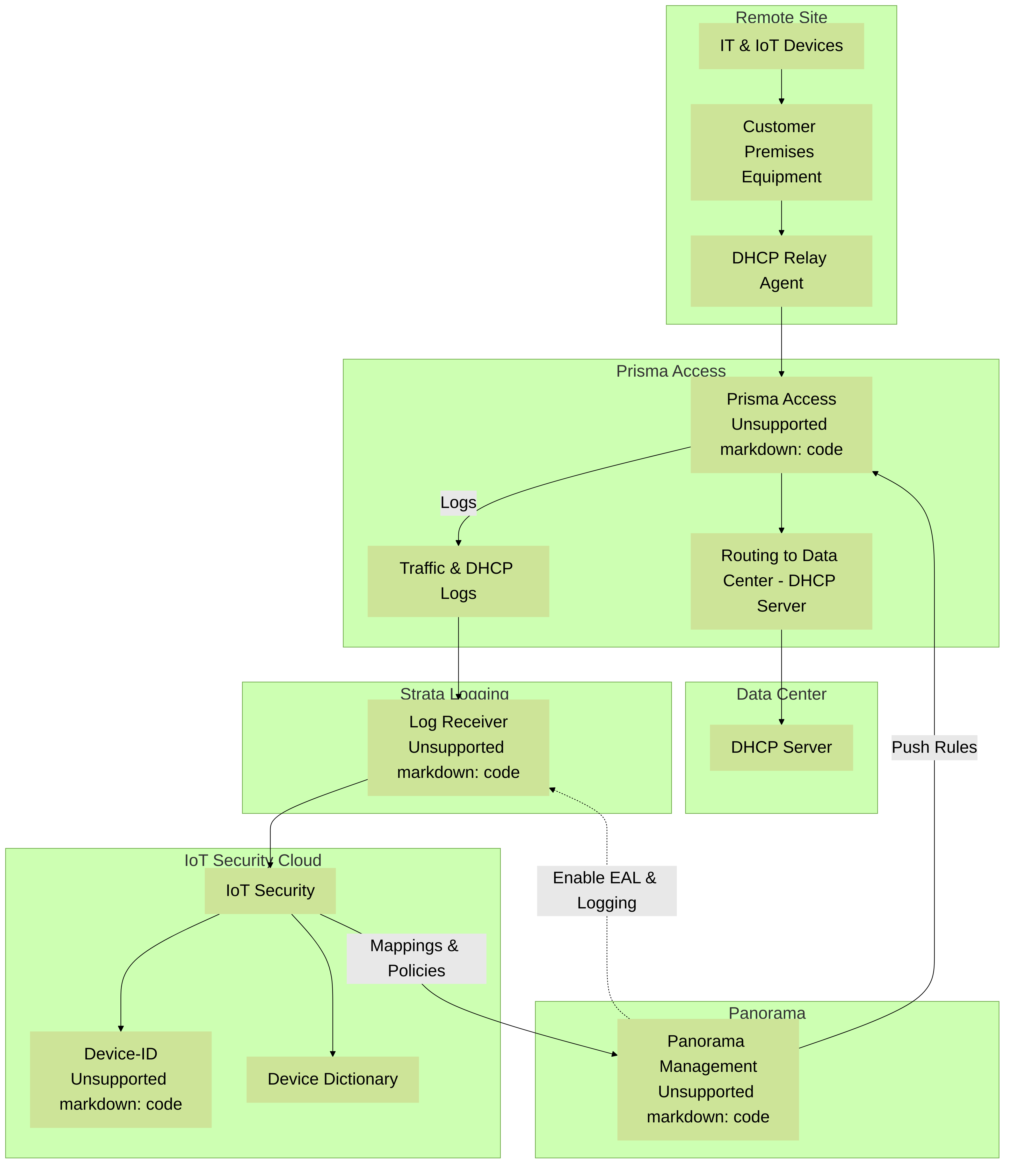
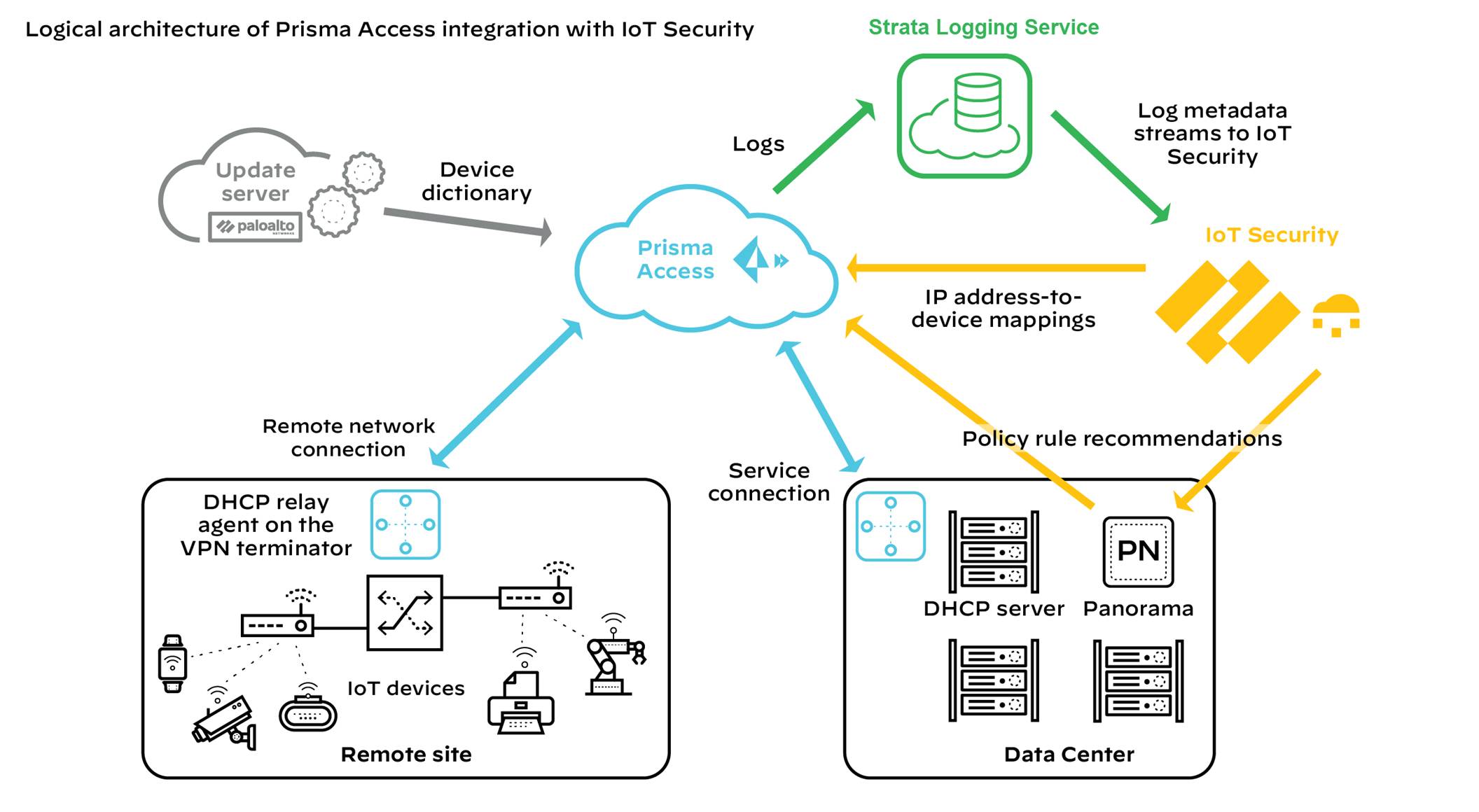
Figure: Architectural overview of IoT Security integration with Prisma Access.
Prisma Access cannot forward logs to IoT Security for Layer 2 traffic or Layer 3 traffic where both the source and destination are in the same site because such traffic never reaches it. Without ARP and DHCP traffic metadata in particular, identifying devices might take IoT Security longer and its confidence might be lower than it otherwise would be. To counter this, consider deploying SD-WAN ION devices at remote sites where they can log these types of traffic and forward their logs to Strata Logging Service for IoT Security to access. By integrating IoT Security with both Prisma Access and SD-WAN, IoT Security can gain visibility into traffic that flows between sites and the Internet as well as traffic that stays within a site.
After IoT Security has sufficient information to identify devices... it provides Prisma Access with IP address-to-device mappings and Panorama with policy recommendations that the Panorama administrator can import and then push to Prisma Access... In addition, Prisma Access downloads device dictionary files from the update server... The combination of IP address-to-device mappings, policy recommendations, and device dictionary files comprise the elements of the Device-ID feature introduced in PAN-OS 10.0.
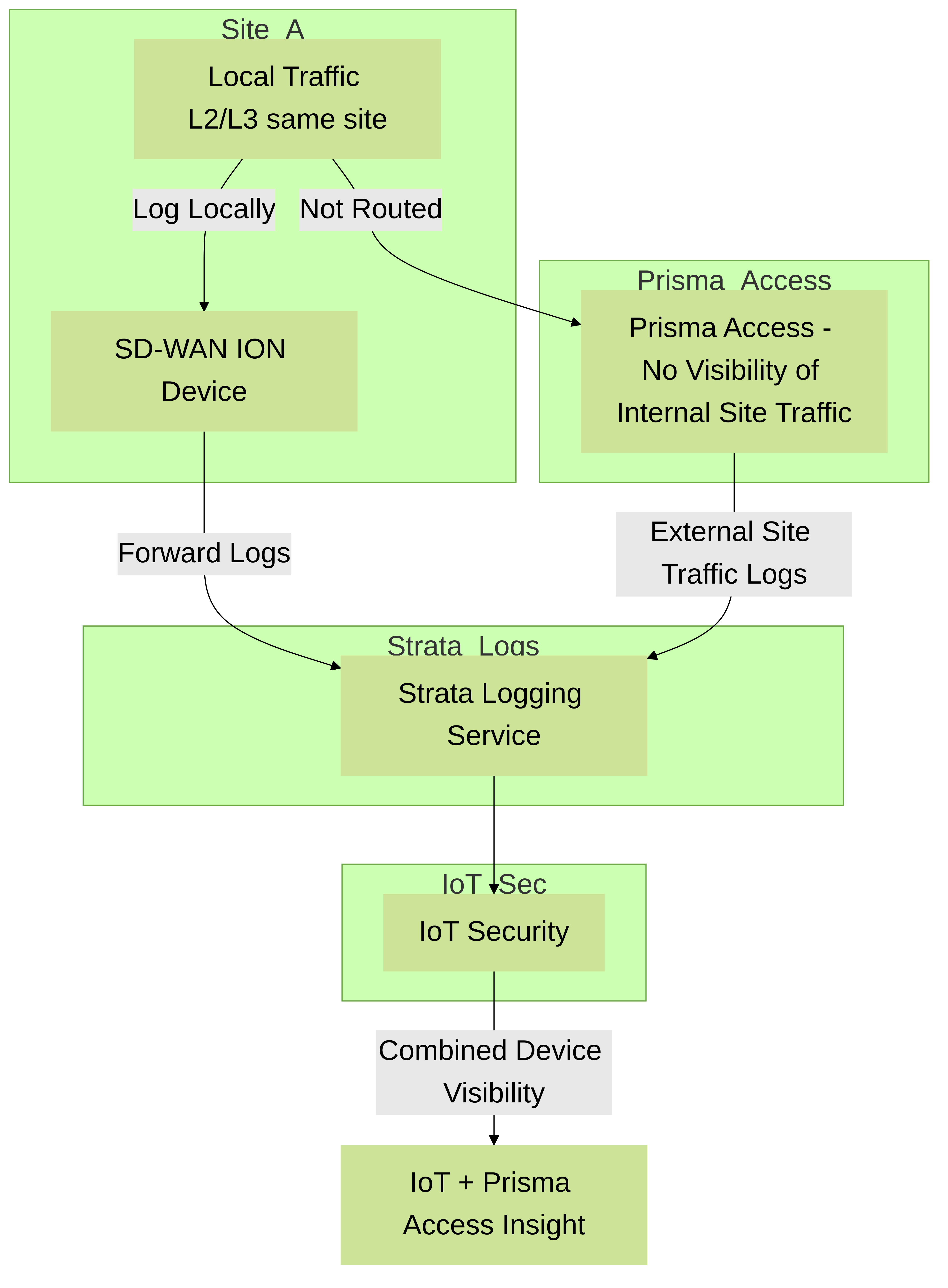
Required Panorama Configuration
Check that you have enabled Enhanced Application Logs on your log forwarding profiles.
- Log in to Panorama and select Objects > Log Forwarding under the Remote_Network_Device_Group device group or a parent device group.
- Open your log forwarding profiles and make sure that Enable enhanced application logging to Strata Logging Service is selected.
Requirements for using IoT Security with Prisma Access
To use the IoT Security add-on with Prisma Access, check that your deployment meets the following requirements:
- Prisma Access is running the Prisma Access 2.0-Innovation release or later.
- You have purchased and activated licenses for Strata Logging Service and the IoT Security add-on for Prisma Access.
If you are a new Panorama-managed Prisma Access customer as of August 2022..., activate new licenses for Prisma Access through the Prisma SASE platform. If you are an existing Panorama-managed Prisma Access customer from before August 2022..., your Prisma Access tenant will be transitioned...
- The deployment of Prisma Access in a particular region requires that the Strata Logging Service instance and IoT Security application it works with to be in a particular location as well. The following table shows the relationship...
| Prisma Access | Strata Logging Service | IoT Security | |
|---|---|---|---|
| Americas | Canada | Canada | Canada |
| United States | United States | United States | |
| European Union | France | France | Germany |
| Germany | Germany | Germany | |
| Italy | Italy | Germany | |
| Poland | Poland | Germany | |
| Spain | Spain | Germany | |
| Netherlands | Netherlands | Germany | |
| Switzerland | Switzerland | Switzerland | |
| United Kingdom | United Kingdom | United Kingdom | |
| Asia-Pacific | Australia | Australia | Australia |
| China | China | Singapore | |
| India | India | Singapore | |
| Indonesia | Indonesia | Singapore | |
| Japan | Japan | Japan | |
| Singapore | Singapore | Singapore |
- You’re using Panorama 10.0 or later to manage Prisma Access. With a mixed deployment of Prisma Access and on-premises next-generation firewalls, you must use the same Panorama management system to manage them and the same IoT Security tenant for both.
- DHCP is being served from a data center or from some other central site.
- The Prisma Access infrastructure provides routing from remote sites to data center resources, which include the DHCP server.
- A DHCP relay agent on the VPN terminator at all remote sites points to the IP address of the DHCP server in the data center.
- Security policy rules in Prisma Access control traffic..., Logging is enabled on these policies and Prisma Access forwards logging data to Strata Logging Service, which streams it to IoT Security. IoT Security uses Enhanced Application logs (EALs), traffic logs (which include DHCP traffic), threat logs, and wildfire logs. Make sure that your policy rules have logging enabled and are forwarding EALs and traffic logs to Strata Logging Service...
Once these requirements are met, use IoT Security to monitor traffic metadata... Import policy rule recommendations from IoT Security into Panorama or configure Device-ID policy rules directly in Panorama and then push them to Prisma Access for policy enforcement on IoT device traffic.
Navigate the IoT Security Portal
After you onboard IoT Security, activate IoT Security licenses on your firewalls, and deploy them so that they can feed data to the logging service, you’re ready to access the IoT Security portal and begin using it. Log in with your account credentials for the Palo Alto Networks Customer Service Portal.
Figure: Login form for the IoT Security portal.
IoT Security uses Single Sign-on (SSO) to verify your login.
The IoT Security portal fully supports Google Chrome and partially supports Microsoft Edge... It does not officially support Microsoft Internet Explorer, Apple Safari, or any other type of browser.
The portal interface is grouped into several sections.
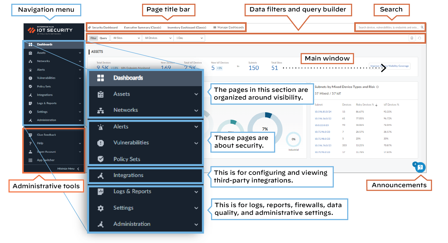
Figure: Overview of the IoT Security portal interface highlighting navigation, search, and filters.
Navigation
The items in the left navigation menu are loosely grouped into four sections... Use the left navigation menu to navigate to different pages... When there are data filters at the top..., use them to control the data that appears... by site, device type, and time period.
Under the navigation menu is a set of administrative tools:
- Give feedback – Leave feedback for IoT Security developers.
- Help – Open the Customer Support Portal.
-
User name (first and last name from the user’s contact information) – When you click the name, these options appear:
- Preferences – Modify your contact information, time zone, idle session timeout, alert sound..., and SMS and email notification settings.
- Resource Center – See status notifications about firewall logs, and learn about IoT Security through recommended resources and useful links
- Dark Theme/Light Theme – Switch between dark and light UI display themes.
- Log out – Log out of your administrative session.
- App Switcher – Take a shortcut to other Palo Alto Networks applications through the hub.
Search
At the top of the page... is a search field where you find data by entering keywords to search for devices, alerts, vulnerabilities, and external destinations.
Data Filters
Below the page title bar and search field... is a set of filters that control the data that the IoT Security portal displays... The filter system consists of global filters and local, page-specific filters. Global filter settings persist while you navigate among different pages... Modified and added filters appear in the UI as blue instead of black... If a page has a default local filter, it appears among the other global filters... For example, the Security Alerts page applies an Active Alerts filter by default...
Query Builder
Next to the data filters is the query builder . Use it to find information about devices, alerts, and vulnerabilities by constructing queries out of various components... A single query can combine devices and security alerts or devices and vulnerabilities... For example, this query shows if the devices in the device profile for APC (Schneider Electric) Smart Power Supply support SNMPv1:
entity = device, Time Range = “month”, Device Type = “All IoT”, [device] Profile = “APC(Schneider Electric) Smart PowerSupply” [vulnerability] Vulnerability = “SNMPv1 Usage”
The results of the query show that 20 IoT devices support SNMPv1 and which ones they are.
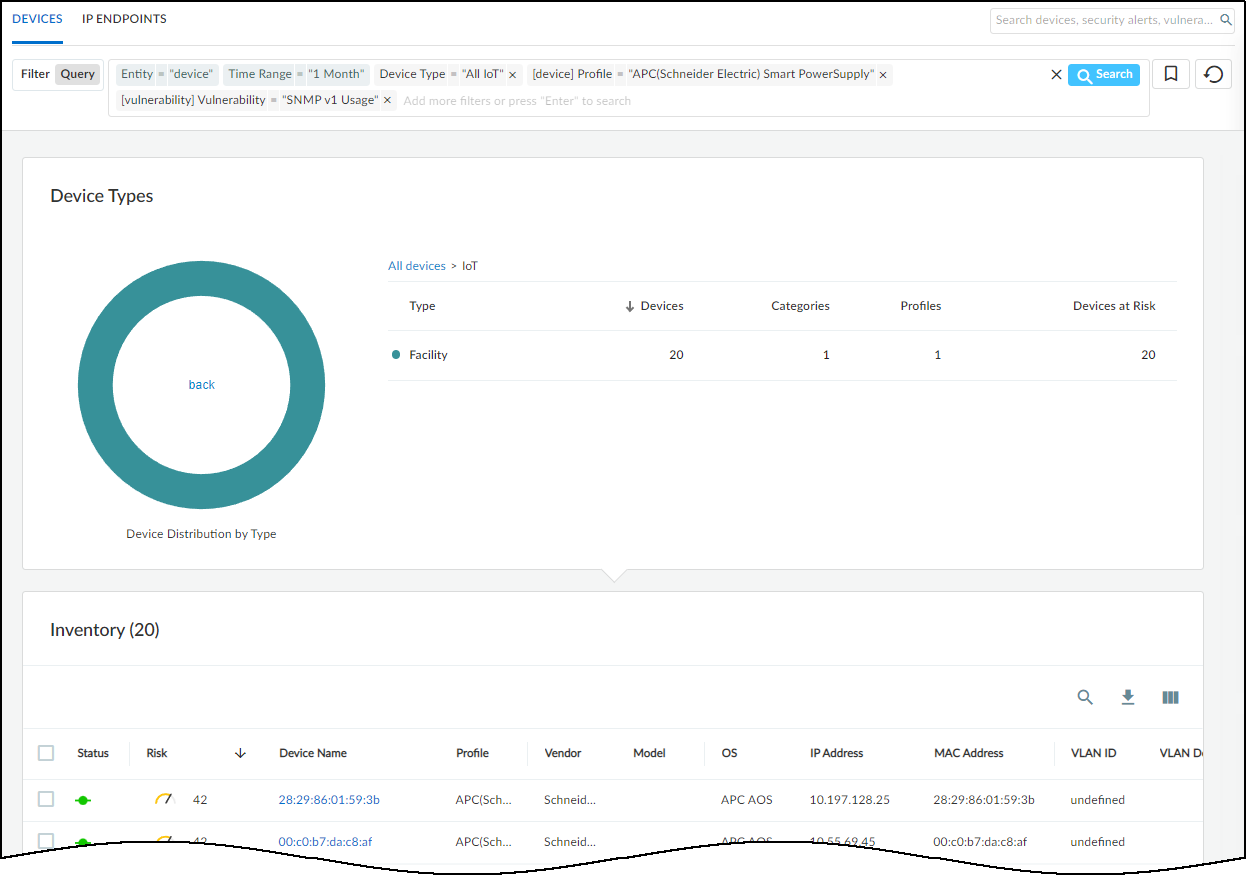
Figure: Example query builder result showing devices matching criteria.
The query tool uses the logic of “AND” between expressions using the operators = (equals), != (doesn’t equal), and IN (includes). For example, the following query fetches data where Time Range = “week” AND Device Type = “All IoT” AND [vulnerability] Severity IN (“High”, “Critical”) :
entity = device, Time Range = “week”, Device Type = “All IoT”, [vulnerability] Severity IN (“High”, “Critical”)

Figure: Query example for devices with high or critical vulnerabilities within a week.
You can save queries so you don't have to recreate ones used repeatedly. To save a query, click the ribbon bookmark icon... and give it a name...
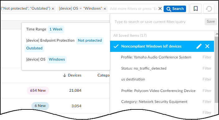
Figure: List of saved queries for quick access.
You cannot save queries from any of the dashboards, such as the Executive Summary.
The query tool has numerous parameters... For example, enter the following query to check which devices were in a vulnerability scan report:
Entity = device, Time Range = “1 Year”, Device Type = “All IoT”, [scanReport] Scan Report = “yes”

Figure: Query example for devices included in vulnerability scan reports.
By looking at the Device Details page of devices in the results... and clicking Vulnerability Report Ready , you can download the report as a PDF...
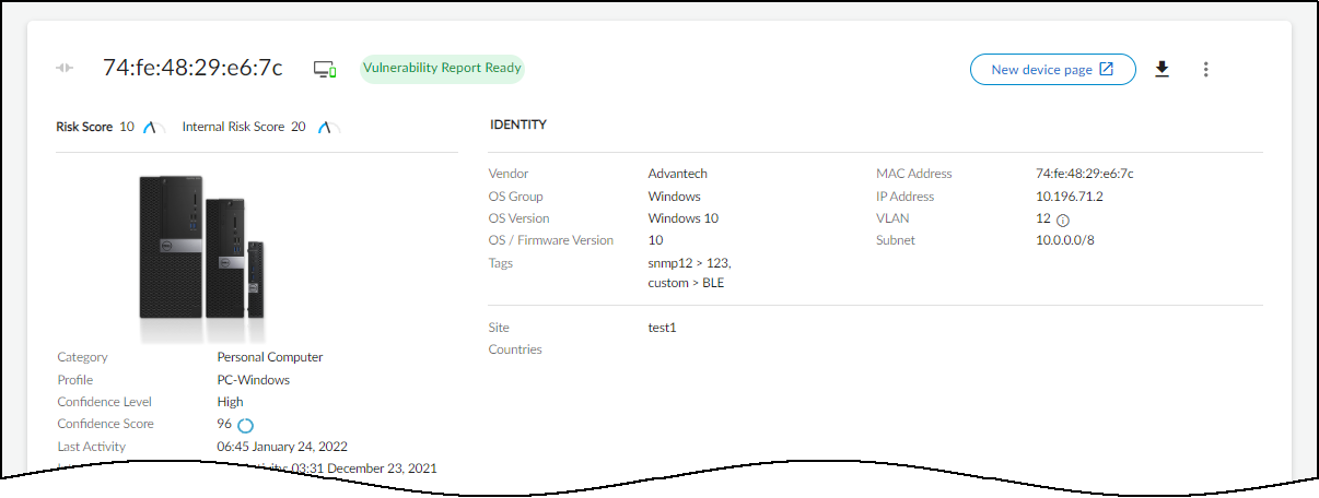
Figure: Option to download the vulnerability report PDF from Device Details.
To help you get started..., IoT Security provides a collection of example templates for common queries. Study these preconfigured queries to learn query builder capabilities, use them as they are, or use them as models...
To see the preconfigured example queries, click Query ... and then click the Query Bookmarks icon.
The preconfigured templates differ somewhat based on the vertical theme that’s active on your IoT Security portal. Each vertical theme has five example templates. Here’s an example for each theme:
Enterprise IoT Security Plus Example Query
- Name: [Example] This Week’s Active Insecure-Login Alerts
- Query: Entity=”alert”, Time Range=”1 Week”, Alert Status=”Active Alerts”, Alert Type IN (“insecure login”, “unsecure login”, “Unsecure login”)
- Summary: This queries IoT Security for all active alerts related to insecure logins over the past week.
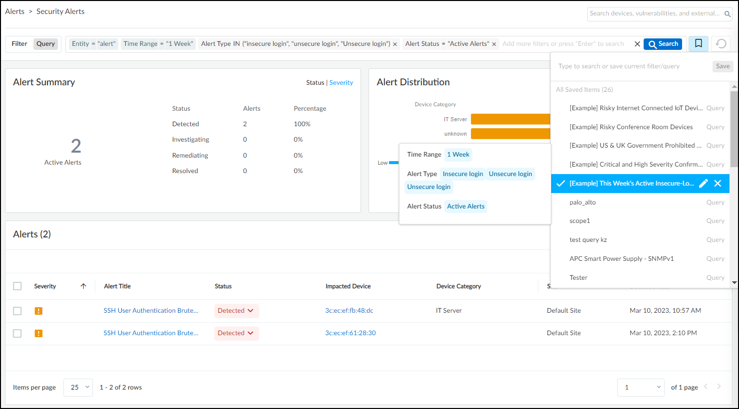
Figure: Example query template for insecure login alerts in Enterprise theme.
Industrial IoT Security Example Query
- Name: [Example] Critical Risk Internet Connected Industrial Devices
- Query: Entity="device", Time Range="1 Year", Device Type="Industrial", [device] Risk = "Critical", [device] Internet Access="yes"
- Summary: This queries IoT Security to show all industrial IoT devices that had a critical risk level and Internet access within the past year.
Medical IoT Security Example Query
- Name: [Example] Risky Internet Connected IoT Devices
- Query: Entity="device", Time Range="1 Year", Device Type="All IoT", [device] Risk IN ("High", "Critical"), [device] Internet Access="yes"
- Summary: This queries IoT Security to show all IoT devices that had a high or critical risk level and Internet access within the past year.
You can edit the expressions that constitute a query template and the template name... You can also delete the example templates.
Announcements
Toggle open and closed a vertical panel on the right side of the UI with information about recent feature releases and important security announcements.
Manage dashboards
When your portal theme has multiple dashboards..., you can control which one is the default, which ones are available in adjacent tabs for quick access, and which ones are hidden... IoT Security lets you set your own preferences to best suit your needs...
- To manage the display of the various dashboards, select Dashboards > Manage Dashboards .
- In the Manage Dashboards drop-down menu, select the check boxes of dashboards you want to display as a tabbed dashboard... Clear the check boxes of those you don’t want displayed... The left-to-right order of tabbed dashboards displayed... corresponds to the top-to-bottom order... with the pinned (preferred) dashboard appearing on the far left.
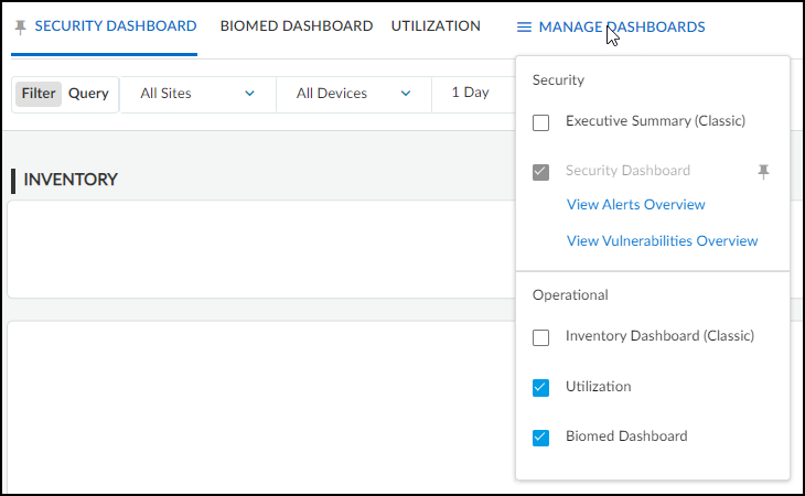
Figure: Managing available and pinned dashboards in the portal.
- To set the default dashboard... click the pushpin icon next to a dashboard name... If you change the portal theme to a vertical that doesn’t include your pinned dashboard, the default dashboard for that vertical becomes the new pinned dashboard.
- To open a new browser tab or window showing security alerts and vulnerabilities, click View Alerts Overview and View Vulnerabilities Overview .
Vertical-themed Portals
The IoT Security portal changes to better serve users in different industries. The portal theme that users in a given IoT Security tenant see depends on two choices:
- The IoT Security product chosen upon purchase
- The theme chosen by an IoT Security tenant owner
Portal Themes
IoT Security provides four differently themed portals for enterprise, industrial, and medical verticals:
- Enterprise IoT Security Plus
- Enterprise IoT Security
- Industrial IoT Security
- Medical IoT Security
Enterprise
IoT Security offers two products for enterprise IoT: Enterprise IoT Security Plus and Enterprise IoT Security.
Enterprise IoT Security Plus is the solution for commercial enterprises and government organizations... It lets you see and secure every IoT device... to meet NIST guidelines. It also helps prevent your IoT devices from becoming the target of cyberattacks. With Enterprise IoT Security Plus, you can do the following:
- Automatically classify devices with over 50 device attributes
- View, edit, confirm, and reclassify devices
- Add devices with static IP addresses
- See your IP address structure and device distribution
- See sites for firewalls and devices
- Generate reports for devices, network behaviors, and security risks
- Integrate with multiple third-party products
- See applications that devices use
- Import policy rule recommendations to firewalls
- Get security alerts for anomalous network activity
- Assess risk and device vulnerabilities
- (Optional) Retain traffic logs
The Security Dashboard, which provides quick access to information about device inventory, alerts, and risks, is shown below. It appears in the Enterprise IoT Security Plus portal as well as in portals for Industrial IoT Security and Medical IoT Security.
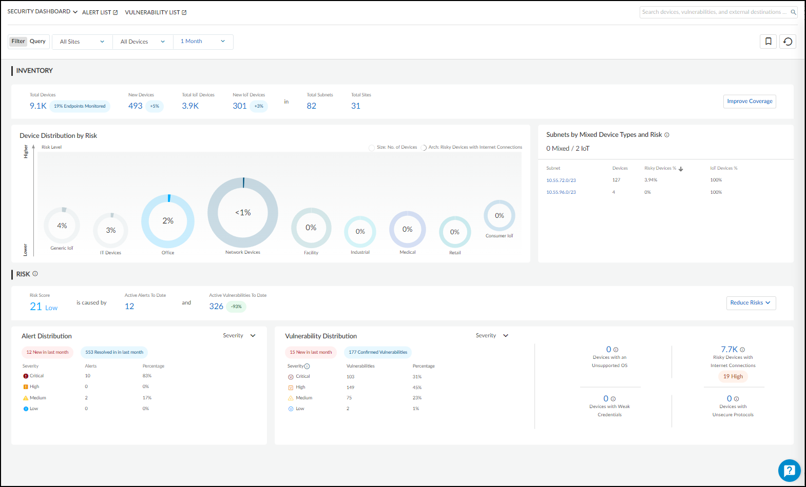
Figure: The Security Dashboard available in Enterprise Plus, Industrial, and Medical themes.
For IoT Security customers with tenants established before 12/15/2022, you can continue using the existing Executive Summary and Inventory dashboards for a limited time. They will eventually be retired and replaced.
Enterprise IoT Security identifies devices in enterprise networks and creates a dynamic device inventory. It does not include the security features and third-party integrations available in Enterprise IoT Security Plus, Industrial OT Security, and Medical IoT Security. Enterprise IoT Security lets you do the following:
- Automatically classify devices with 12 device attributes
- View, edit, confirm, and reclassify devices
- Add devices with static IP addresses
- See your IP address structure and device distribution
- See sites for firewalls and devices
- Generate device reports
The Devices page, shown below, is the default landing page after login to the Enterprise IoT Security portal. Unlike the other vertical-themed product portals, it does not include dashboards.
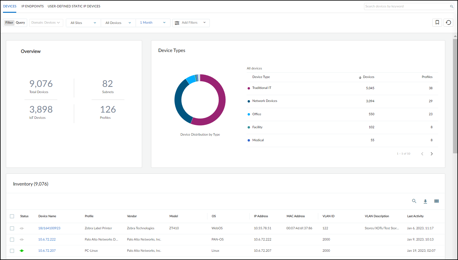
Figure: The Devices page, the default view in the Enterprise IoT Security theme.
For more information, see the Enterprise IoT Security Administrator’s Guide documentation.
Industrial
Industrial IoT Security is the solution for industrial corporations... It lets you see and secure every device..., including specialized operational technology (OT) devices..., so you can keep your operations up at all times and achieve NIST and ISA/IEC compliance. You can do the following with Industrial IoT Security:
- Get everything in Enterprise IoT Security Plus
- Detect OT device anomalies
- Use Purdue levels for device modeling and visualization
- Create customized rules for process integrity
As in the portal for Enterprise IoT Security Plus, the Industrial IoT Security portal also includes the Security dashboard.
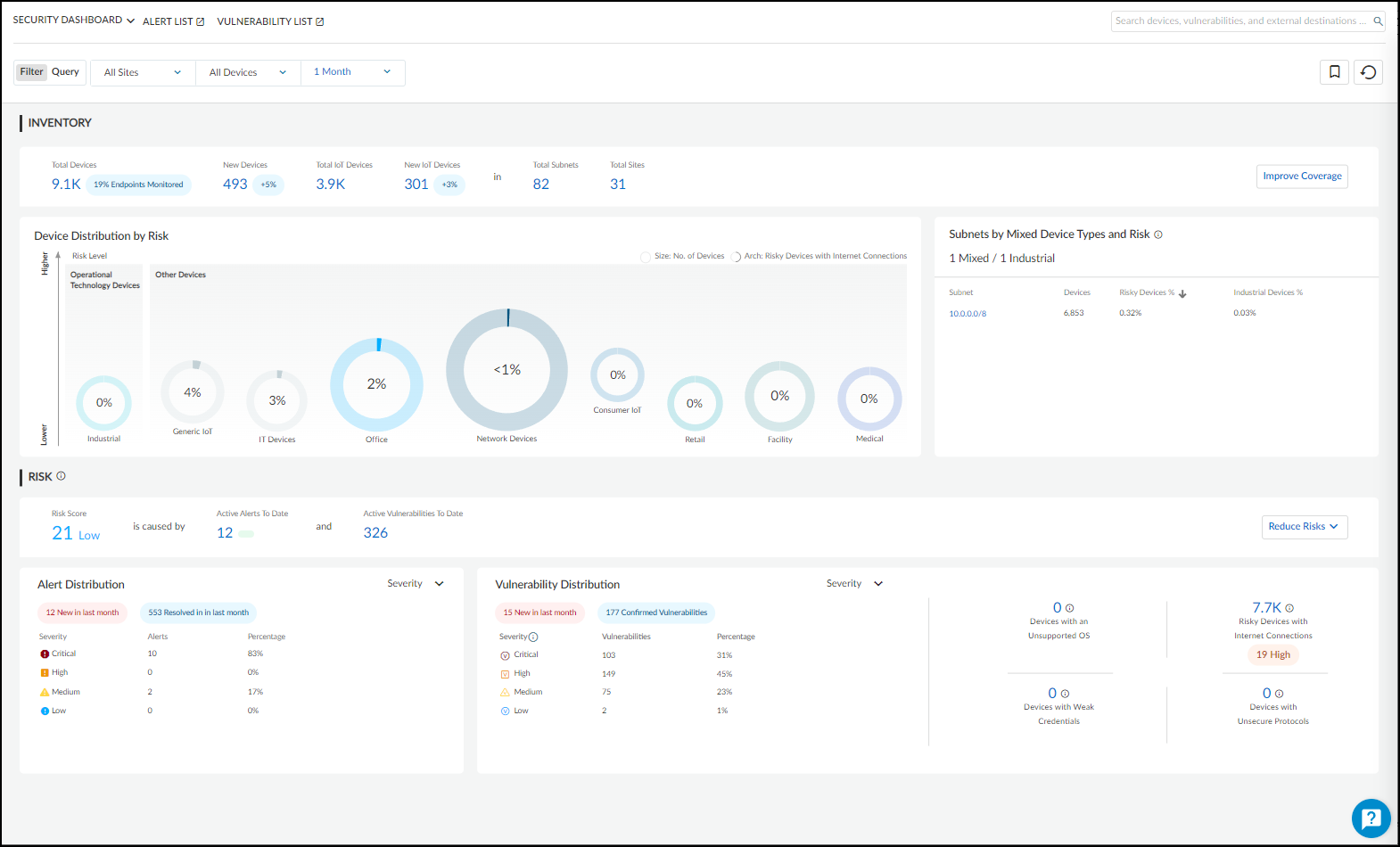
Figure: The Security Dashboard in the Industrial IoT Security theme.
It's not uncommon for industrial networks to include one or more air-gapped segments. .. Through the use of next-generation firewalls configured as security telemetry gateways, you can provide IoT Security services for device in such networks.
Medical
Medical IoT Security is the solution for healthcare providers... It lets you see and secure every device... including specialized medical devices..., so you can deliver high-quality patient care and achieve HIPAA compliance. Use Medical IoT Security to do the following:
- Get everything in Enterprise IoT Security Plus
- Detect medical device anomalies
- Assess medical device risk leveraging FDA recalls , PHI identification , and MDS2
- Track medical device utilization
The portal for Medical IoT Security displays two pages that are relevant only to medical IoT and only appear when the Medical IoT Security theme is activated. One is for Food and Drug Administration (FDA) recalls and another is for Manufacturer Disclosure Statement for Medical Device Safety (MDS2) forms. When using the Medical IoT Security theme, the portal also includes two dashboards with data just about medical IoT devices: the Utilization dashboard and, shown below, BioMed dashboard.
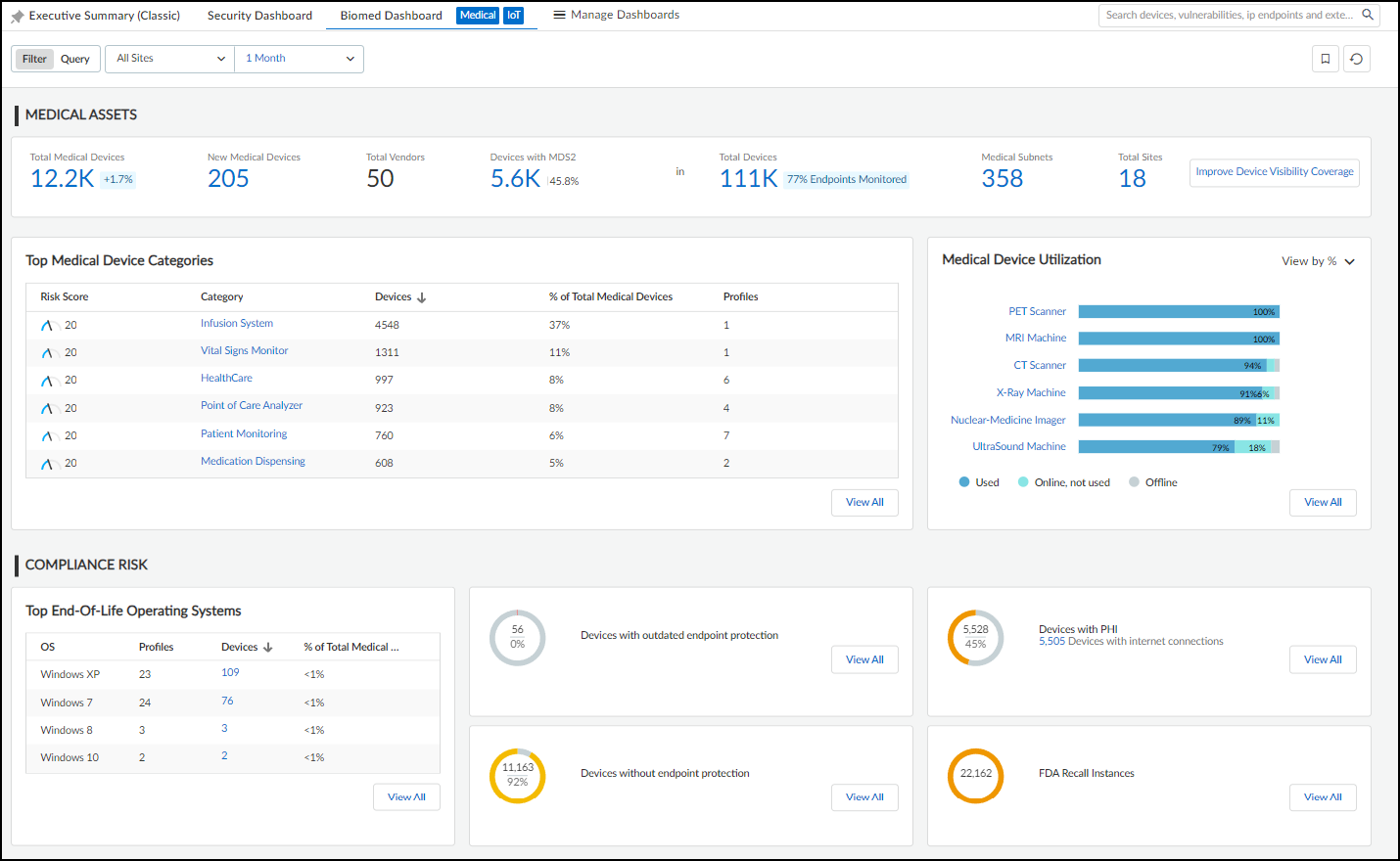
Figure: The BioMed Dashboard specific to the Medical IoT Security theme.
For more information, see Medical IoT documentation.
Switch Portal Themes
A tenant can only have one theme at a time... however, it’s possible for tenant owners to switch themes. When users first log in... and a theme has already been defined..., then that theme is automatically loaded by default. However, if you purchased multiple IoT Security products with different themes (or if you have an IoT Security product purchased prior to December 15, 2022), then IoT Security prompts owners to select a theme when they initially log in... If an owner doesn’t make a selection, IoT Security shows the Enterprise IoT Security Plus theme and continues to prompt owners... Once a selection has been made, all other users in the same tenant will also see the same theme when they access the portal.
To switch vertical themes, log in as a user with owner privileges, select Administration > About > License . The status indicates which theme is currently in use... Click Switch next to the name of the theme that's currently in use.
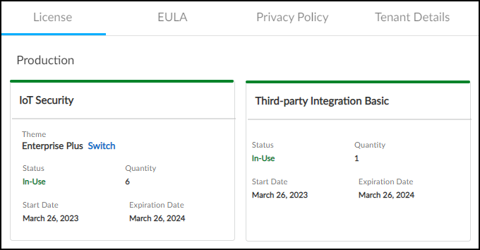
Figure: Option to switch the vertical theme in the License information section.
Select a new theme, and then click Confirm .
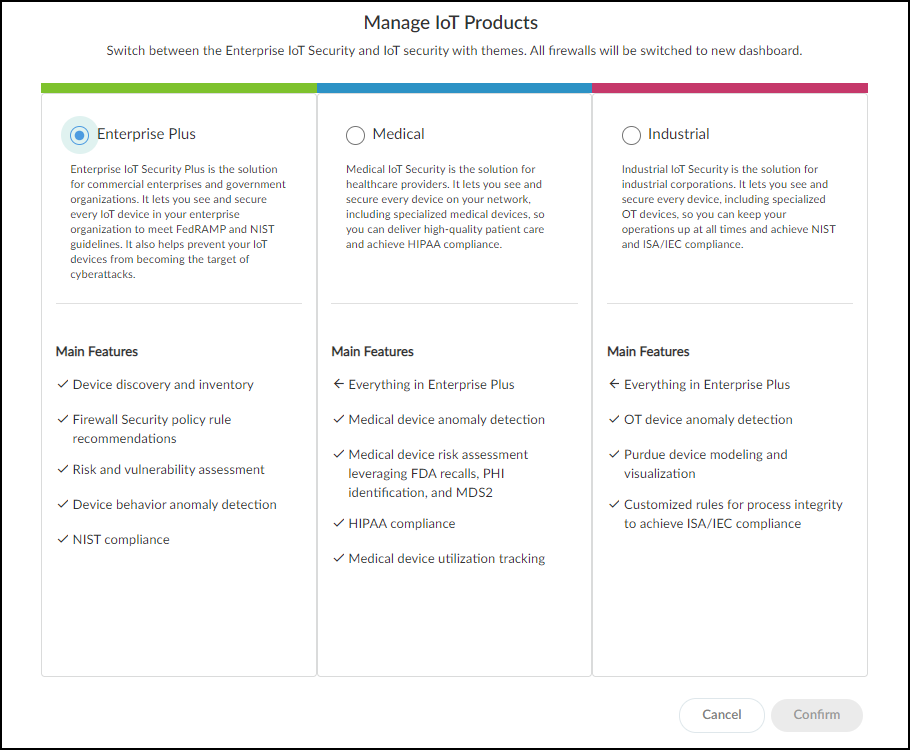
Figure: Dialog for selecting the desired vertical theme.
As an owner, you can switch themes for your tenant as many times as you like.
Create a Trial Enterprise IoT Security Tenant
If you have a production license for Enterprise IoT Security Plus, Industrial IoT Security, or Medical IoT Security and want to see what Enterprise IoT Security is like, you can create a one-time trial tenant and assign up to five of your firewalls to it. The trial is valid for 30 days. During that time, both the production and trial tenants consume log data... When the trial period ends and the trial tenant is automatically deleted, the production IoT Security tenant alone continues consuming the log data from the firewalls.
- To initiate a trial, log in to the IoT Security portal with a user account that has Owner privileges.
- Select Administration > About > License and then click Request next to Enterprise IoT Security in the Trial section.
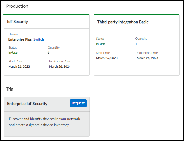
Figure: Requesting a trial for Enterprise IoT Security from a production tenant.
- Choose up to five firewalls that you want to use for the trial and then Save .
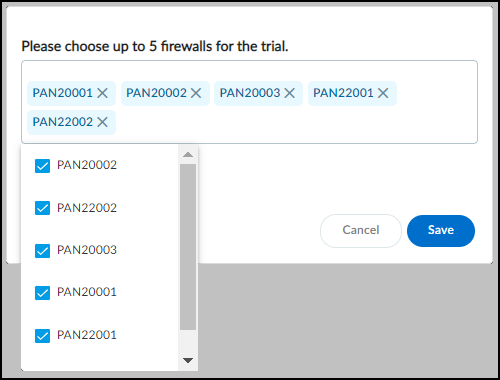
Figure: Selecting firewalls to be included in the trial tenant.
A message appears explaining that a trial tenant... is being created... The trial tenant creation and firewall assignments are also recorded in Logs & Reports > Audit Log .
- On Administration > About > License , the button next to Enterprise IoT Security in the Trial section changes from Request to Enter . To access the trial tenant portal, click Enter . A login prompt appears for the trial tenant in a new browser window.
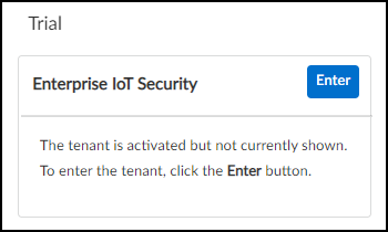
Figure: Button to enter the trial tenant portal.
- Log in with the same credentials you used to log in to the production IoT Security tenant. The Enterprise IoT Security portal opens... and is ready for use... During the 30-day trial, both the IoT Security tenant and the Enterprise IoT Security trial tenant will consume logs from the firewalls assigned to the trial tenant. You can log in to both tenants and compare the functionality of each.
- To exit the trial tenant and return to the production tenant, navigate to Administration > About > License and then click Enter next to IoT Security in the Production section.
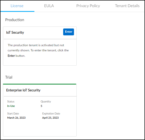
Figure: Button to return to the production tenant portal.
The trial tenant browser window remains open while the production tenant opens in a new browser window.
After the trial ends, the trial tenant is automatically deleted while the production tenant continues consuming log data from the firewalls.
If you have a trial license for IoT Security and want to try out the Enterprise IoT Security product, log in to the IoT Security portal with a user account that has Owner privileges, select Administration > About > License, and then click Manage Trial . Select Enterprise and then Confirm . To go back..., click Manage Trial again, select Enterprise Plus , and Confirm .
Interactive Quiz: Test Your IoT Security Knowledge
Test your understanding of key concepts and configurations discussed in the documentation.