NAT64 Overview
NAT64 provides a way to transition to IPv6 while you still need to communicate with IPv4 networks . When you need to communicate from an IPv6-only network to an IPv4 network, you use NAT64 to translate source and destination addresses from IPv6 to IPv4 and vice versa. NAT64 allows IPv6 clients to access IPv4 servers and allows IPv4 clients to access IPv6 servers . You should understand NAT before configuring NAT64.
Simplified Explanation
Imagine you have devices that only speak IPv6, but they need to talk to servers or services that only understand IPv4 (like many websites on the older internet). NAT64 acts as a translator at the network edge (typically your firewall).
- IPv6 Client to IPv4 Server: When your IPv6 device wants to reach an IPv4 server, NAT64 translates the IPv6 source address into an IPv4 source address ( often sharing one IPv4 address among many IPv6 clients, similar to traditional NAT ) and converts the special destination IPv6 address (containing the IPv4 address) into the actual IPv4 destination address.
- IPv4 Client to IPv6 Server: When an IPv4 device needs to reach an internal IPv6 server, NAT64 translates the IPv4 source address into a special IPv6 address ( embedding the IPv4 address ) and maps the public IPv4 destination address to the specific internal IPv6 server address.
In essence, NAT64 bridges the communication gap between IPv6-only and IPv4-only networks, facilitating the gradual transition to IPv6. For the IPv6-to-IPv4 direction, it often works alongside a **DNS64** server , which tricks the IPv6 client into thinking the IPv4 server has an IPv6 address by providing a specially crafted IPv6 address that embeds the real IPv4 address.
Operation Details
You can configure two types of NAT64 translation on a Palo Alto Networks® firewall; each one is doing a bidirectional translation between the two IP address families:
- The firewall supports stateful NAT64 for IPv6-Initiated Communication , which maps multiple IPv6 addresses to one IPv4 address, thus preserving IPv4 addresses. ( It does not support stateless NAT64 , which maps one IPv6 address to one IPv4 address and therefore does not preserve IPv4 addresses.) Configure NAT64 for IPv6-Initiated Communication.
- The firewall supports IPv4-initiated communication with a static binding that maps an IPv4 address and port number to an IPv6 address. Configure NAT64 for IPv4-Initiated Communication. It also supports port rewrite , which preserves even more IPv4 addresses by translating an IPv4 address and port number to an IPv6 address with multiple port numbers. Configure NAT64 for IPv4-Initiated Communication with Port Translation.
A single IPv4 address can be used for NAT44 and NAT64 ; you don’t reserve a pool of IPv4 addresses for NAT64 only.
NAT64 operates on Layer 3 interfaces, subinterfaces, and tunnel interfaces. To use NAT64 on a Palo Alto Networks firewall for IPv6-initiated communication, you must have a third-party DNS64 Server or a solution in place to separate the DNS query function from the NAT function. The DNS64 server translates between your IPv6 host and an IPv4 DNS server by encoding the IPv4 address it receives from a public DNS server into an IPv6 address for the IPv6 host.
Palo Alto Networks supports the following NAT64 features:
- ( PAN-OS 10.1.6 and later 10.1 releases ) Beginning with PAN-OS 10.1.6, persistent NAT for DIPP is available on VM-Series firewalls and single-dataplane firewalls. Beginning with PAN-OS 10.1.7, it is available on all firewalls.
- Hairpinning (NAT U-Turn); additionally, NAT64 prevents hairpinning loop attacks by dropping all incoming IPv6 packets that have a source prefix of 64::/n.
- Translation of TCP/UDP/ICMP packets per RFC 6146 and the firewall makes a best effort to translate other protocols that don’t use an application-level gateway (ALG). For example, the firewall can translate a GRE packet. This translation has the same limitation as NAT44: if you don’t have an ALG for a protocol that can use a separate control and data channel, the firewall might not understand the return traffic flow.
- Translation between IPv4 and IPv6 of the ICMP length attribute of the original datagram field, per RFC 4884.
IPv4-Embedded IPv6 Address
NAT64 uses an IPv4-embedded IPv6 address as described in RFC 6052, IPv6 Addressing of IPv4/IPv6 Translators. An IPv4-embedded IPv6 address is an IPv6 address in which 32 bits have an IPv4 address encoded in them . The IPv6 prefix length (PL in the figure) determines where in the IPv6 address the IPv4 address is encoded, as follows:
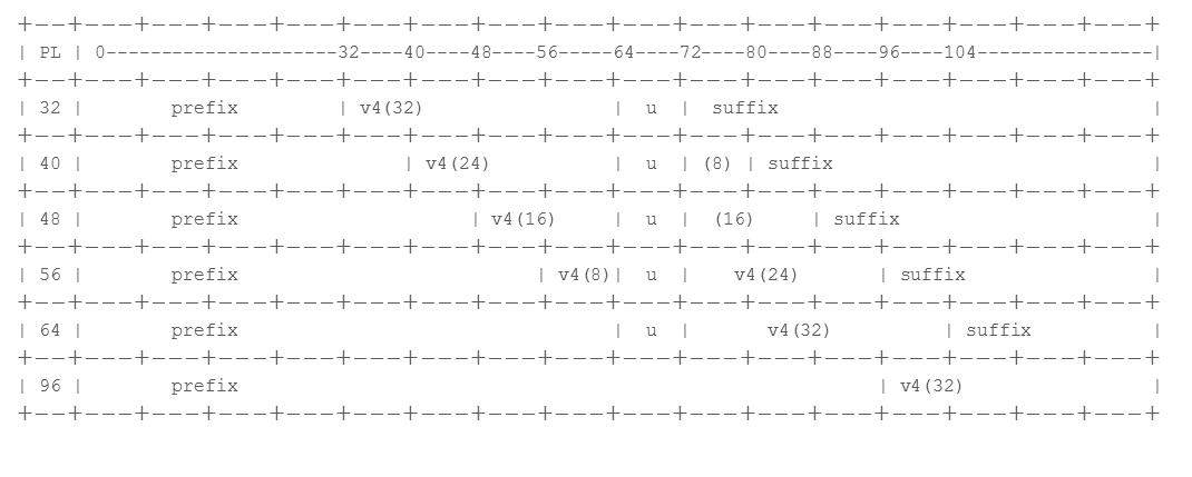
The firewall supports translation for /32, /40, /48, /56, /64, and /96 subnets using these prefixes. A single firewall supports multiple prefixes; each NAT64 rule uses one prefix. The prefix can be the Well-Known Prefix (64:FF9B::/96) or a Network-Specific Prefix (NSP) that is unique to the organization that controls the address translator (the DNS64 device). An NSP is usually a network within the organization’s IPv6 prefix. The DNS64 device typically sets the u field and suffix to zeros; the firewall ignores those fields.
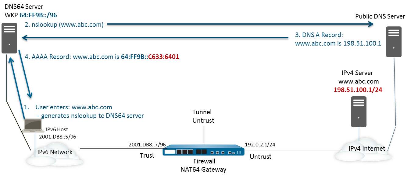
DNS64 Server
If you need to use a DNS and you want to perform NAT64 translation using IPv6-Initiated Communication, you must use a third-party DNS64 server or other DNS64 solution that is set up with the Well-Known Prefix or your NSP. When an IPv6 host attempts to access an IPv4 host or domain on the internet, the DNS64 server queries an authoritative DNS server for the IPv4 address mapped to that host name. The DNS server returns an Address record (A record) to the DNS64 server containing the IPv4 address for the host name.
The DNS64 server in turn converts the IPv4 address to hexadecimal and encodes it into the appropriate octets of the IPv6 prefix it is set up to use (the Well-Known Prefix or your NSP) based on the prefix length, which results in an IPv4-Embedded IPv6 Address. The DNS64 server sends an AAAA record to the IPv6 host that maps the IPv4-embedded IPv6 address to the IPv4 host name.
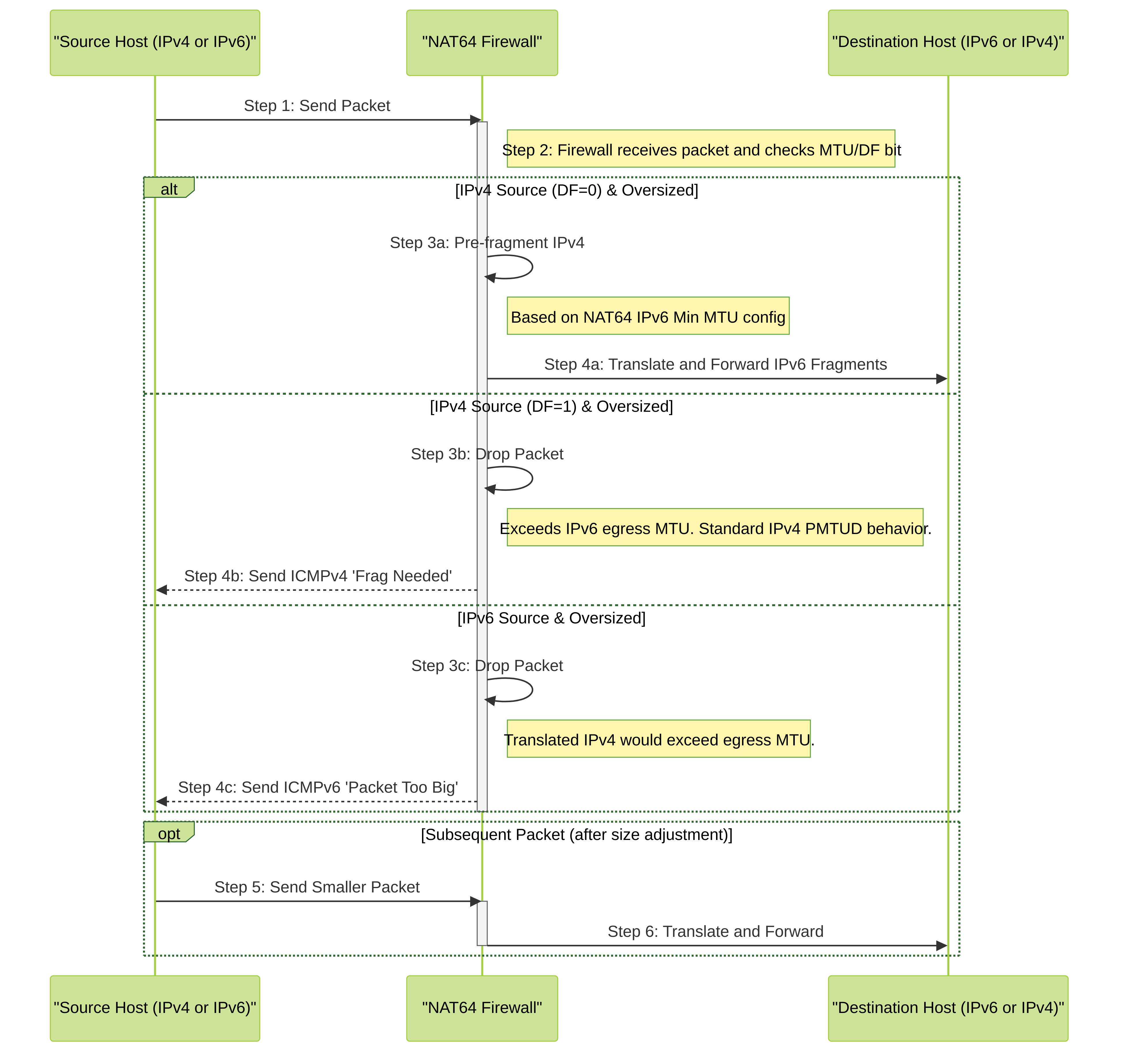
Path MTU Discovery
IPv6 does not fragment packets in-transit like IPv4 routers can, relying instead on endpoints adjusting their packet size based on Path MTU Discovery (PMTUD). The firewall uses two methods to handle potential MTU issues during NAT64 translation:
- When the firewall is translating IPv4 packets to IPv6 and the original IPv4 packet has the DF (don’t fragment) bit set to zero (meaning fragmentation is allowed), the firewall *can* preemptively fragment the IPv4 packet *before* translation if needed. This ensures the resulting IPv6 packet conforms to a minimum expected MTU on the IPv6 side. You configure this minimum expected MTU using the NAT64 IPv6 Minimum Network MTU setting ( Device > Setup > Session > Session Settings ). This complies with RFC 6145, IP/ICMP Translation Algorithm. Setting this value lower forces more fragmentation on the IPv4 side before translation; setting it higher reduces pre-fragmentation. (Note: This does not change the actual interface MTU.)
- When translating IPv4 to IPv6, if an incoming IPv4 packet *has* the DF bit set (meaning do not fragment) and the packet size (plus the IPv6 header overhead) exceeds the MTU of the firewall's egress IPv6 interface, the firewall performs standard PMTUD behavior for IPv4: it drops the oversized packet and sends an ICMPv4 'Destination Unreachable - Fragmentation Needed and DF set' message back to the original IPv4 source. This signals the source to reduce its packet size for that destination. Similarly, when translating IPv6 to IPv4, if the resulting IPv4 packet would exceed the IPv4 egress MTU, the firewall sends an ICMPv6 'Packet Too Big' message back to the IPv6 source.
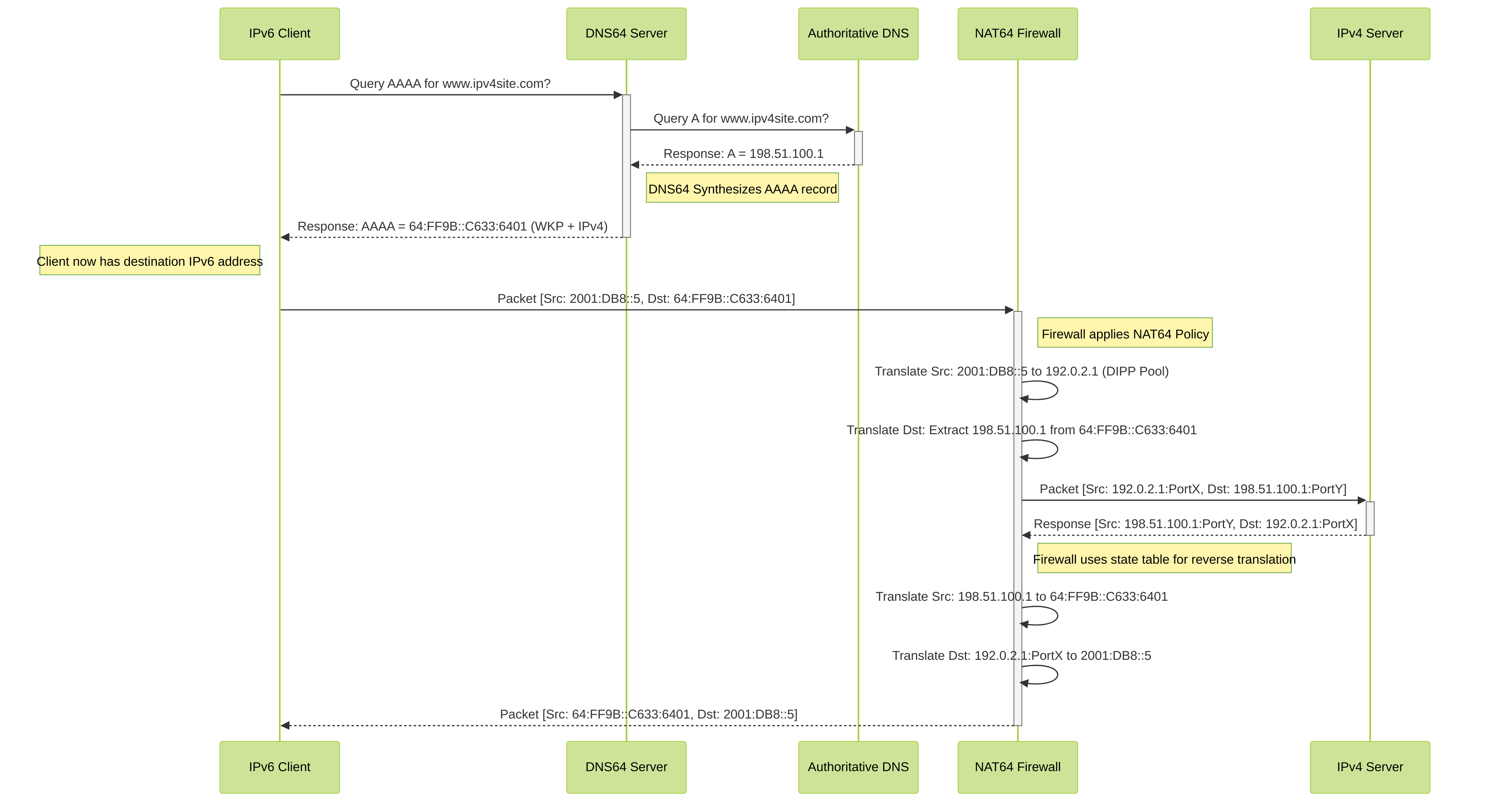
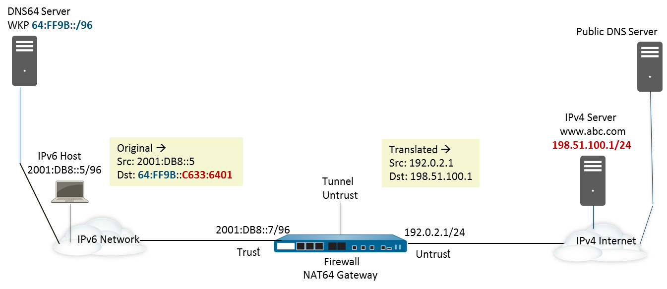
IPv6-Initiated Communication Flow (with DNS64)
This diagram illustrates how an IPv6 client connects to an IPv4 server using NAT64 and DNS64.
Explanation:
- The IPv6 client asks the DNS64 server for the IPv6 address (AAAA record) of an IPv4-only site.
- The DNS64 server asks the regular DNS for the IPv4 address (A record).
- The regular DNS replies with the IPv4 address.
- The DNS64 server creates a fake IPv6 address by combining a special prefix (like the Well-Known Prefix 64:FF9B::/96) with the IPv4 address encoded within it. It sends this synthetic AAAA record back to the client.
- The IPv6 client sends its packet towards this synthetic IPv6 destination address.
- The NAT64 firewall intercepts the packet. It translates the client's IPv6 source address to an IPv4 address from its pool (Dynamic IP and Port). It extracts the *real* IPv4 destination address from the synthetic IPv6 destination address.
- The firewall forwards the translated packet (now fully IPv4) to the IPv4 server.
- Return traffic follows the reverse path, with the firewall using its state table to translate addresses back to IPv6 for the client.
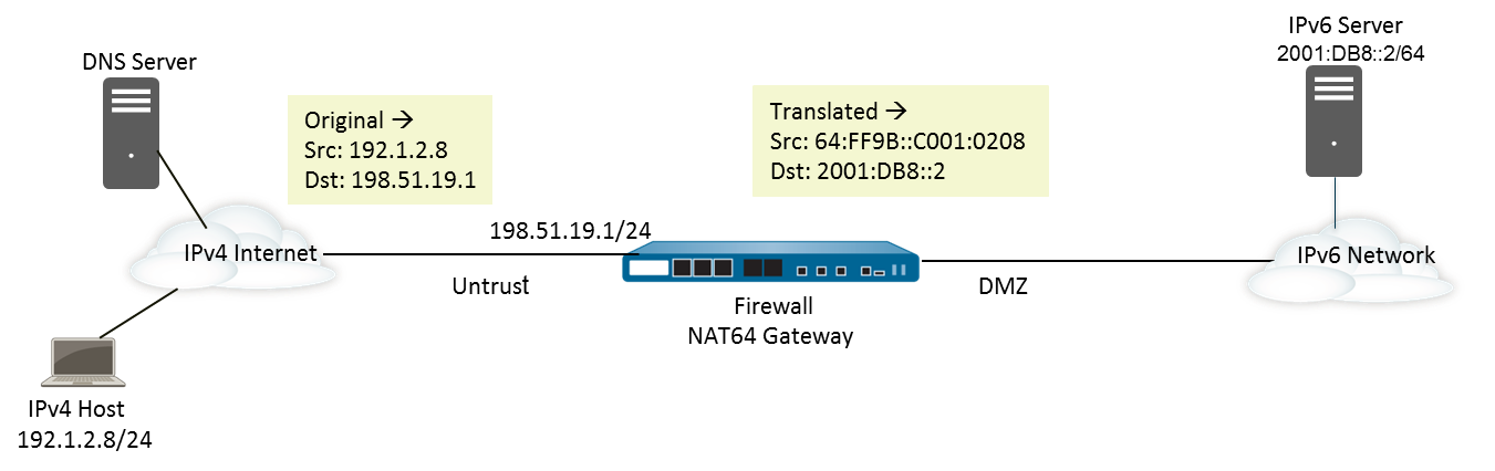
IPv4-Initiated Communication Flow
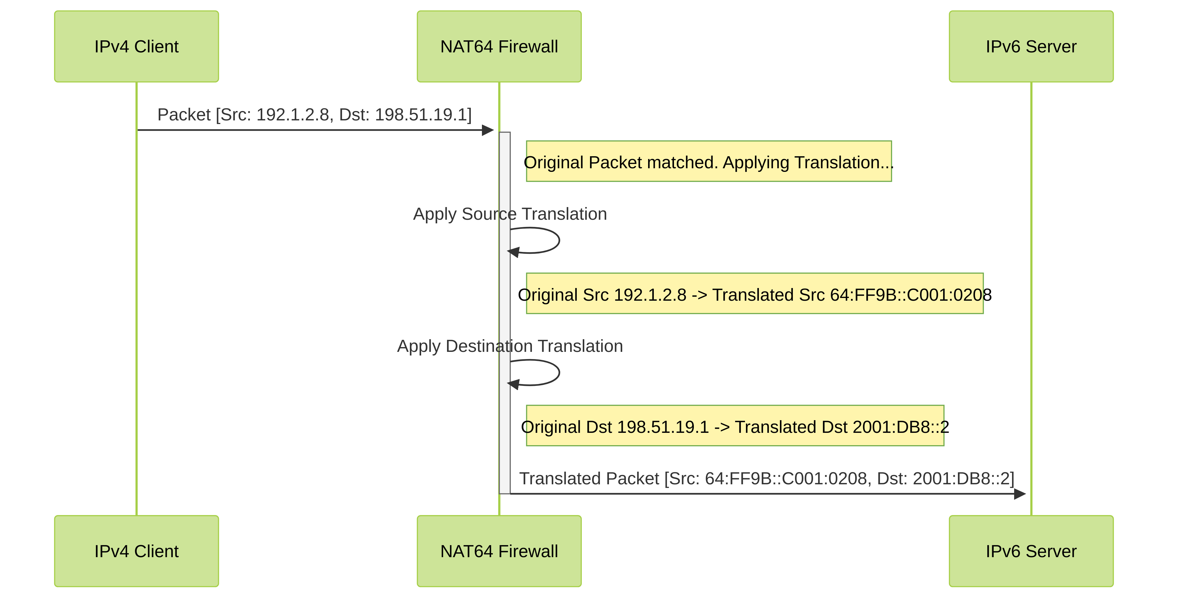
This diagram shows an external IPv4 client connecting to an internal IPv6 server via NAT64.
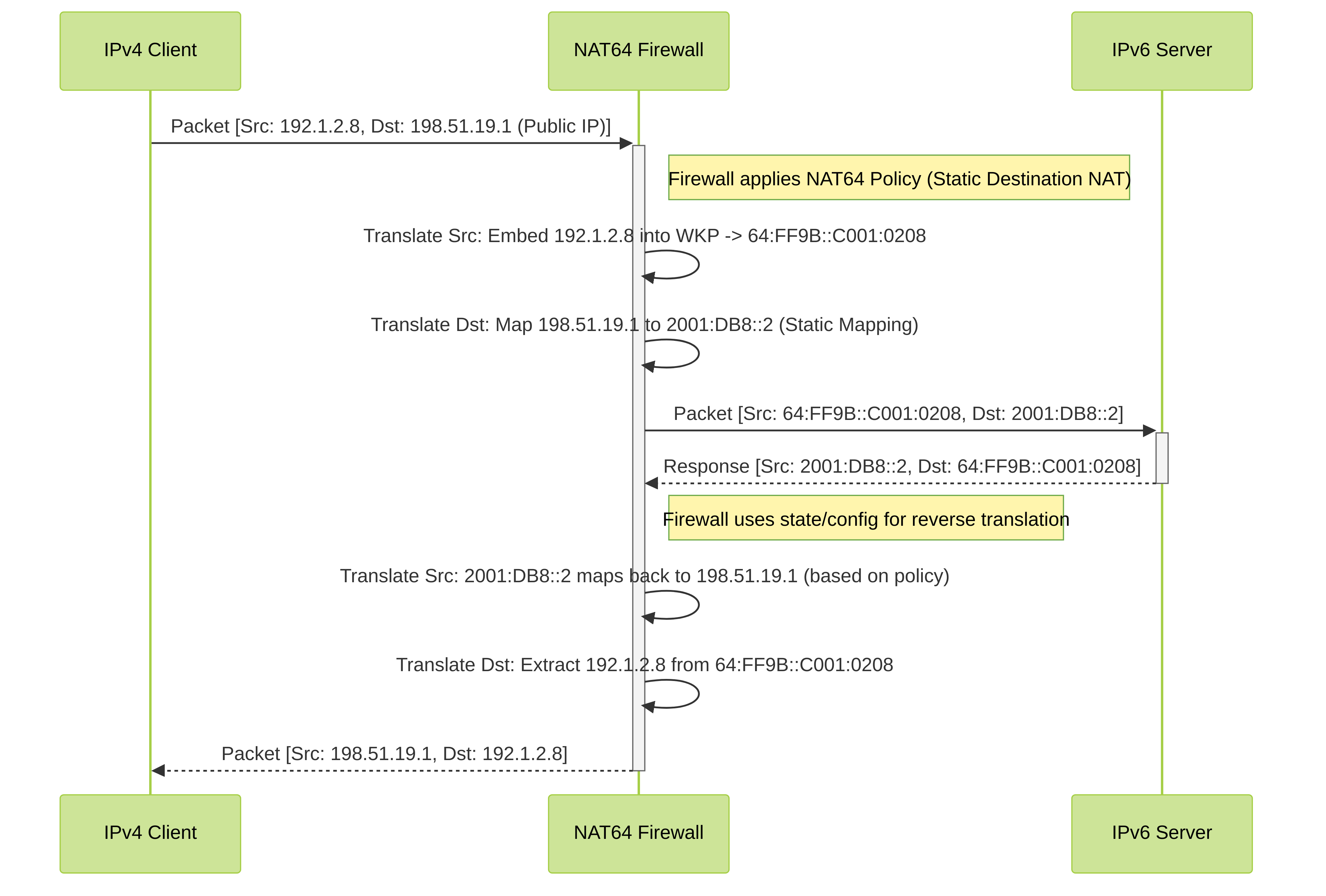
Explanation:
- An external IPv4 client sends a packet to a public IPv4 address configured on the firewall for NAT64 destination translation.
- The NAT64 firewall intercepts the packet based on a matching NAT policy.
- It translates the IPv4 source address into an IPv4-embedded IPv6 address using a prefix like 64:FF9B::/96.
- It translates the public IPv4 destination address to the pre-configured internal IPv6 server address (Static IP translation) . Port translation can also occur here if configured.
- The firewall forwards the translated packet (now fully IPv6) to the internal IPv6 server.
- Return traffic follows the reverse path, with the firewall translating addresses back to IPv4 for the external client.
Configure NAT64 for IPv6-Initiated Communication
This configuration task and its addresses correspond to the figures in IPv6-Initiated Communication.
Beginning with PAN-OS 10.1.6, you can enable persistent NAT for DIPP to mitigate the compatibility issues that symmetric NAT may have with applications that use STUN.
-
Enable IPv6 to operate on the firewall.
- Select Device > Setup > Session and edit the Session Settings.
- Select Enable IPv6 Firewalling .
- Click OK .
-
Configure the necessary interfaces with IPv6 addressing.
-
Configure the internal-facing (Trust) interface: Select
Network > Interfaces > Ethernet
and select the interface. On the
IPv6
tab, select
Enable IPv6 address on interface
and
Add
your internal IPv6 prefix (e.g.,
2001:DB8::/64). -
Configure the external-facing (Untrust) interface: Select the interface. On the
IPv4
tab,
assign the IPv4 address to be used for NAT
(e.g.,
192.0.2.1/24). Ensure IPv4 connectivity is established.
-
Configure the internal-facing (Trust) interface: Select
Network > Interfaces > Ethernet
and select the interface. On the
IPv6
tab, select
Enable IPv6 address on interface
and
Add
your internal IPv6 prefix (e.g.,
-
Create an address object for the IPv6 destination address prefix (pre-translation).
- Select Objects > Addresses and click Add .
-
Enter a
Name
for the object, for example,
nat64-prefix-wkp. -
For
Type
, select
IP Netmask
and enter the
IPv6 prefix used by DNS64
, with a netmask compliant with RFC 6052 (/32, /40, /48, /56, /64, or /96). This is either the Well-Known Prefix or your Network-Specific Prefix. For this example, enter
64:FF9B::/96. - Click OK .
(You don't enter a full destination address because, based on the prefix length, the firewall extracts the encoded IPv4 address from the original destination IPv6 address in the incoming packet.)
-
(Optional) Create an address object for the internal IPv6 source network (pre-translation).
- Select Objects > Addresses and click Add .
-
Enter a
Name
for the object, e.g.,
Internal_IPv6_Net. -
For
Type
, select
IP Netmask
and enter the address of the internal IPv6 network, e.g.,
2001:DB8::/64. - Click OK .
-
(Optional) Create an address object for the translated IPv4 source address pool if not using the interface address.
- Select Objects > Addresses and click Add .
-
Enter a
Name
for the object, e.g.,
NAT64_IPv4_Pool. -
For
Type
, select
IP Netmask
(or Range) and enter the IPv4 address(es) to be used for translation, e.g.,
192.0.2.1/32. - Click OK .
-
Create the NAT64 rule.
- Select Policies > NAT and click Add .
-
On the
General
tab, enter a
Name
for the NAT64 rule, for example,
nat64_ipv6_initiated. - (Optional) Enter a Description .
- For NAT Type , select nat64 .
-
Specify the original source and destination information (Original Packet tab).
- For Source Zone , Add the zone where your IPv6 clients reside (e.g., Trust).
- For Destination Zone , select the zone associated with the NAT64 prefix via the tunnel interface (e.g., Untrust).
-
(Optional) Select a
Destination Interface
(usually
anyunless specific routing is needed). -
For
Source Address
, select
Any
or
Add
the address object for your internal IPv6 network (e.g.,
Internal_IPv6_Net). -
For
Destination Address
,
Add
the address object you created for the NAT64 prefix
(e.g.,
nat64-prefix-wkp). - (Optional) For Service , select any or specify services if needed.
-
Specify the translated packet information (Translated Packet tab).
- Under Source Address Translation , for Translation Type , select Dynamic IP and Port (for stateful NAT64).
-
For
Address Type
, do one of the following:
-
Select
Translated Address
and
Add
the address object for the IPv4 pool (e.g.,
NAT64_IPv4_Pool). - Select Interface Address , then select the firewall's external (Untrust) Interface and optionally specify an IP Address if the interface has multiple.
-
Select
Translated Address
and
Add
the address object for the IPv4 pool (e.g.,
- Leave Destination Address Translation unselected (set to None ). The firewall derives this automatically from the original destination packet and the NAT64 prefix.
- Click OK to save the NAT64 policy rule.
-
Configure a tunnel interface to handle routing for the NAT64 prefix.
- Select Network > Interfaces > Tunnel and Add a tunnel.
-
For
Interface Name
, enter a numeric suffix, such as
tunnel.64. - On the Config tab, select the Virtual Router used for your external routing.
- For Security Zone , select the destination zone where the IPv4 servers reside (e.g., Untrust).
- On the IPv6 tab, select Enable IPv6 on the interface .
- Click Add under Addresses.
-
Enter the NAT64 prefix
(e.g.,
64:FF9B::/96). You might need to create a temporary address object or just type it in, depending on the PAN-OS version's UI flexibility here. *Assigning an actual address from the prefix like64:FF9B::1/96might be required by the UI, even though it's just for routing association.* - Click OK .
- Click OK again to save the tunnel interface configuration.
-
**Crucially:** Add a static route for the NAT64 prefix pointing to this tunnel interface.
Go to
Network > Virtual Routers > [Your Router] > Static Routes > IPv6
. Add a route for
64:FF9B::/96(or your NSP prefix) with the Interface set to the tunnel you just created (e.g.,tunnel.64) and Next Hop type asNone. This directs traffic destined for the synthetic prefix towards the correct zone via the tunnel.
-
Create a security policy to allow the translated traffic.
- Select Policies > Security and Add a rule.
-
Give it a
Name
(e.g.,
Allow_NAT64_Outbound). -
On the
Source
tab, select the
Source Zone
(e.g., Trust) and specify the
Source Address
(e.g.,
Internal_IPv6_NetorAny). -
On the
Destination
tab, select the
Destination Zone
(e.g., Untrust). For
Destination Address
, you can specify
Any(as the final destination is IPv4) or be more specific if possible. *Note: The Security Policy evaluates the packet *after* NAT lookup but often *before* the final translation occurs for new sessions, so matching based on original packet zones and addresses is typical.* Some versions might require matching the NAT64 prefix in the destination here if zone determination relies on it before NAT policy applies fully. Test carefully. The most reliable is usually Source Zone Trust -> Destination Zone Untrust. -
On the
Application
and
Service/URL Category
tabs, specify allowed applications/services (e.g.,
web-browsing,ssl, orany). - On the Actions tab, set the Action to Allow .
- Click OK .
-
Commit your changes.
- Click Commit .
-
(PAN-OS 10.1.6+) Optionally enable persistent NAT for DIPP via CLI.
- Access the CLI.
-
Run:
set system setting persistent-dipp enable yes -
Run:
request restart system(Requires system reboot) - If using HA, repeat on the peer after rebooting the first.
-
Troubleshoot or view a NAT64 session via CLI.
- Access the CLI.
-
Run:
show session id - Look for flags indicating NAT64 and inspect the translated addresses.
Configure NAT64 for IPv4-Initiated Communication
IPv4-initiated communication to an IPv6 server is similar to destination NAT in an IPv4 topology. The destination IPv4 address (usually a public IP on the firewall) maps to the internal destination IPv6 address through a one-to-one, static IP translation .
The firewall encodes the source IPv4 address into an IPv4-embedded IPv6 prefix (like the Well-Known Prefix 64:FF9B::/96 as defined in RFC 6052) for the translated source. The translated destination address is the actual IPv6 address of the internal server. The use case for IPv4-initiated communication is typically when an organization is providing access from the public, untrust zone (IPv4 world) to an internal IPv6 server in the organization's DMZ or Trust zone. This topology does not typically require a DNS64 server for the connection itself.
-
Enable IPv6 to operate on the firewall.
- Select Device > Setup > Session and edit the Session Settings.
- Select Enable IPv6 Firewalling .
- Click OK .
-
(Optional) Configure MTU handling for IPv4 DF=0 packets.
- Select Device > Setup > Session and edit Session Settings.
- Set NAT64 IPv6 Minimum Network MTU (range is 1280-9216, default is 1280) as needed. Lower values cause more pre-fragmentation of IPv4 packets before translation. Setting it high (e.g., 9216) minimizes pre-fragmentation, relying more on PMTUD ICMP messages if needed.
- Click OK .
-
Create an address object for the public IPv4 destination address (pre-translation). This is the address external clients will connect to.
- Select Objects > Addresses and click Add .
-
Enter a
Name
, e.g.,
Public_IPv4_for_Server. -
For
Type
, select
IP Netmask
and enter the public IPv4 address.
It must use no netmask or a /32 netmask only
for static destination NAT. Example:
198.51.19.1/32. - Click OK .
-
Create an address object for the NAT64 prefix to be used for the *translated source* address. This is the prefix the firewall will use to embed the original IPv4 source.
- Select Objects > Addresses and click Add .
-
Enter a
Name
, e.g.,
nat64-prefix-wkp. -
For
Type
, select
IP Netmask
and enter the NAT64 IPv6 prefix with a compliant netmask (e.g., /96). Example:
64:FF9B::/96. - Click OK .
(The firewall uses this prefix and embeds the original IPv4 source address into it to create the translated IPv6 source address, e.g.,
64:FF9B::C001:0208if the source was192.1.2.8). -
Create an address object for the internal IPv6 destination server address (translated). This is the real internal address of the server.
- Select Objects > Addresses and click Add .
-
Enter a
Name
, e.g.,
Internal_IPv6_Server. -
For
Type
, select
IP Netmask
and enter the actual IPv6 address of the internal server.
The address must use no netmask or a /128 netmask only
for static destination NAT. Example:
2001:DB8::2/128. - Click OK .
-
Create the NAT64 rule. This defines the overall translation behavior.
- Select Policies > NAT and click Add .
-
On the
General
tab, enter a
Name
, e.g.,
nat64_ipv4_initiated. - For NAT Type , select nat64 .
-
Specify the original packet information (Original Packet tab). This determines which incoming packets the rule will match.
- For Source Zone , Add the zone where external IPv4 clients reside (e.g., Untrust).
- Select the Destination Zone (usually the Untrust zone as well, as the destination IP is on the firewall's external interface).
-
For
Source Address
, select
Any
or specify allowed external IPv4 source networks/addresses (e.g.,
Any, or a specific range like192.1.2.0/24). -
For
Destination Address
,
Add
the address object for the public IPv4 address
(e.g.,
Public_IPv4_for_Server, representing198.51.19.1). -
For
Service
, select
any
or the specific service(s) the server offers (e.g.,
service-http,service-https).
-
Specify the translated packet information (Translated Packet tab). This defines how the source and destination addresses (and potentially ports) will be changed.
- Under Source Address Translation , set Translation Type to Static IP . This is the key step for the source translation in this scenario.
-
For
Translated Address
, select the address object representing the NAT64 prefix
(e.g.,
nat64-prefix-wkp, representing64:FF9B::/96). The firewall will automatically embed the original source IPv4 into this prefix to create the translated IPv6 source address (e.g.,64:FF9B::C001:0208if original source was192.1.2.8). -
Under
Destination Address Translation
, for
Translated Address
, specify the address object for the internal IPv6 server
(e.g.,
Internal_IPv6_Server, representing2001:DB8::2/128). This is the static, one-to-one mapping for the destination. - (Optional for Port Translation - see next section) Leave Translated Port blank for direct port mapping.
- Click OK .
-
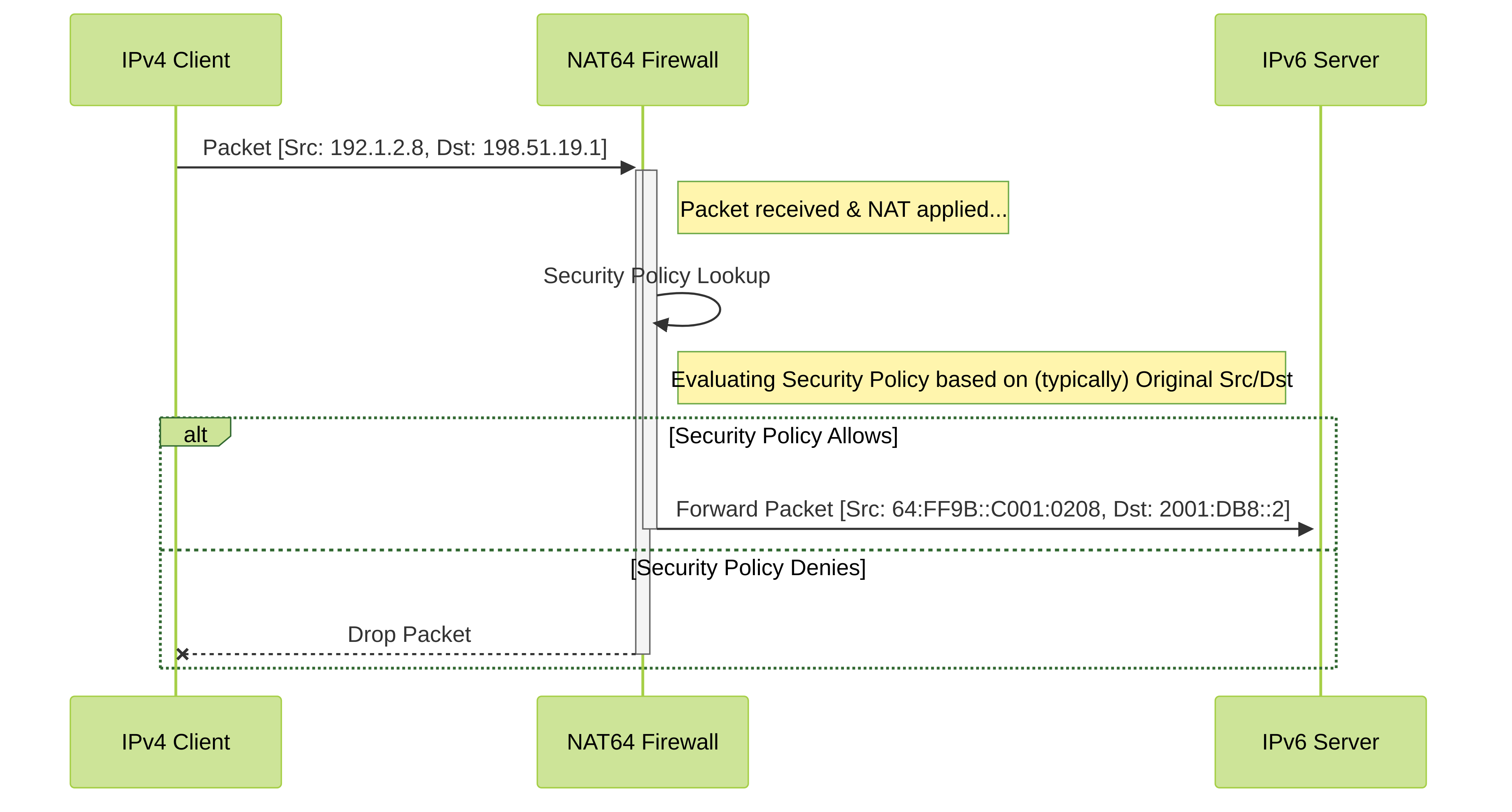
Create a security policy to allow the traffic to the internal server. This policy acts as a firewall rule, permitting or denying the traffic after the NAT lookup determines the destination zone.
- Select Policies > Security and Add a rule.
-
Give it a
Name
(e.g.,
Allow_NAT64_Inbound). -
On the
Source
tab, select the
Source Zone
(e.g., Untrust) and specify allowed
Source Address
es (e.g.,
Any). -
On the
Destination
tab, select the
Destination Zone
where the IPv6 server resides (e.g., DMZ or Trust). For
Destination Address
, specify the *original* public IPv4 address object
(
Public_IPv4_for_Server, representing198.51.19.1). The security policy typically matches on the original destination before NAT redirects it internally. - On the Service/URL Category tab, specify the allowed Service(s) (matching the NAT rule).
- On the Actions tab, set the Action to Allow .
- Click OK .
-
Commit your changes.
- Click Commit .
-
(PAN-OS 10.1.6+) Optionally enable persistent NAT for DIPP via CLI.
- Access the CLI.
-
Run:
set system setting persistent-dipp enable yes -
Run:
request restart system(Requires system reboot) - If using HA, repeat on the peer after rebooting the first.
-
Troubleshoot or view sessions as needed.
- Access the CLI.
-
Run:
show session id
At this point, the firewall knows to look for packets coming from the Untrust zone, going to the Untrust zone destination address
198.51.19.1
(or the object
Public_IPv4_for_Server
), and potentially for specific services.
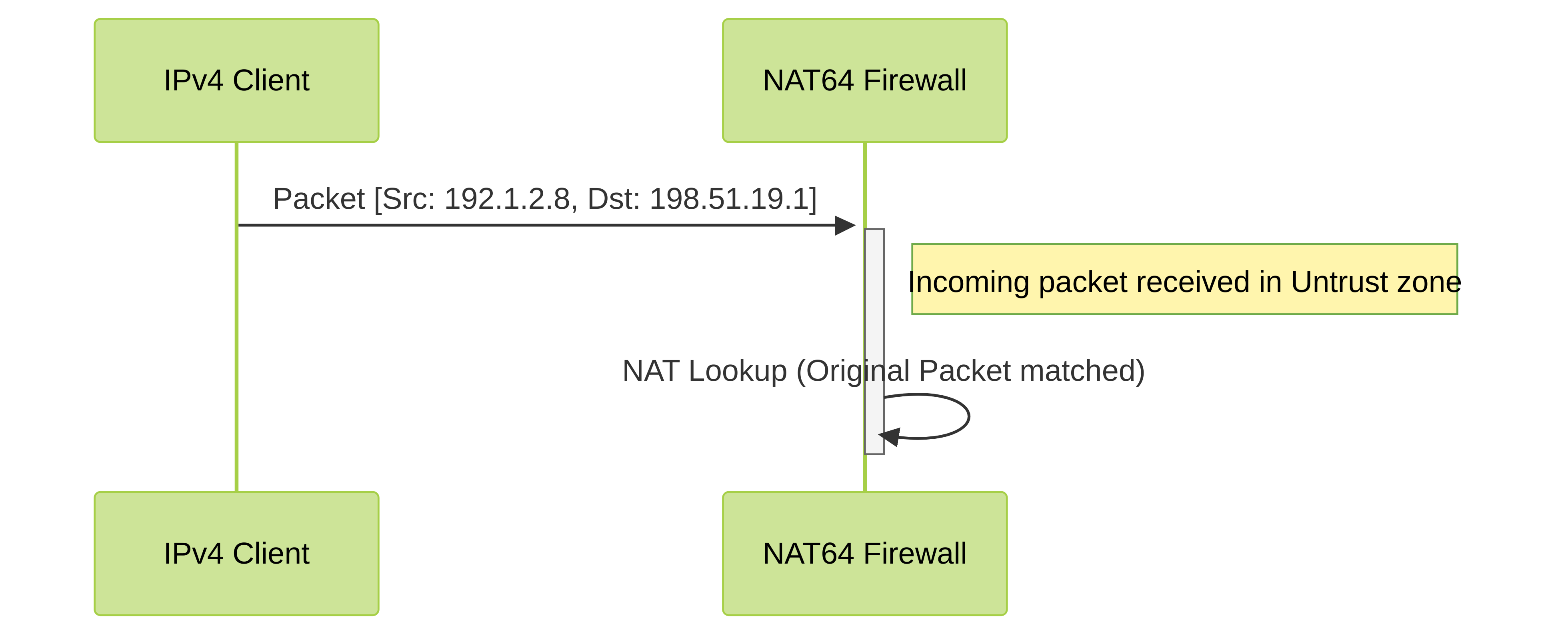
Now the firewall knows how to translate the packet once it matches the rule.
The translated packet is now sent towards the internal IPv6 server. The server responds, and the firewall uses its session state (created by the NAT rule) to perform the reverse translation automatically.
This security rule now permits the traffic matching the original source/destination from the Untrust zone to the internal zone.
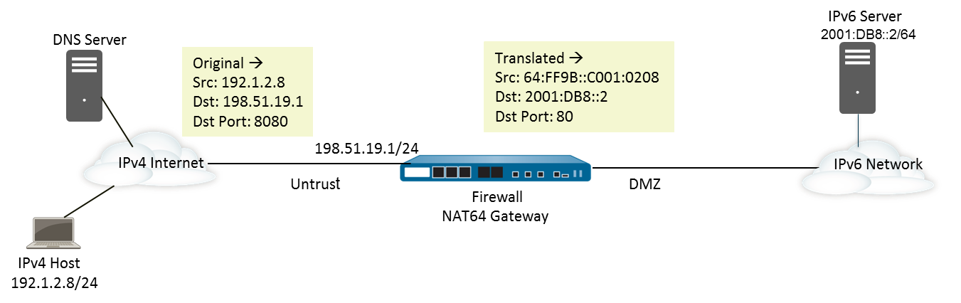
Configure NAT64 for IPv4-Initiated Communication with Port Translation
This task builds on the previous configuration (IPv4-Initiated Communication), but adds port translation . This is useful if the organization wants to expose a service on a standard external port (e.g., 8080) but have it map to a different internal port on the IPv6 server (e.g., 80). This can obscure the internal port usage.
To achieve this, you modify the NAT64 rule:
- In the **Original Packet** tab, you specify the **Service** object that defines the *external* protocol and port number (e.g., TCP port 8080).
- In the **Translated Packet** tab, under **Destination Address Translation**, you specify the **Translated Port** number (e.g., 80).
- Follow steps 1-6 from the "Configure NAT64 for IPv4-Initiated Communication" section (Enable IPv6, configure MTU, create address objects for Public IPv4 Dest, NAT64 Prefix, and Internal IPv6 Server Dest).
-
Modify the NAT64 rule creation (Steps 7 & 8 from the previous section):
-
When configuring the **Original Packet** tab (Step 7):
-
For
Service
, instead of
anyorservice-http, click Add or select an existing Service object that defines the *external* port . For example, create a service namedtcp-8080for Protocol TCP and Destination Port 8080. Select this service.
-
For
Service
, instead of
-
When configuring the **Translated Packet** tab (Step 8):
- Specify Source Address Translation (Static IP, using NAT64 prefix) and Destination Address Translation (using Internal IPv6 Server address object) as before.
-
In the **Destination Address Translation** section, enter the
*internal* port number in the **Translated Port** field
. For this example, enter
80.
- Click OK to save the NAT rule.
-
When configuring the **Original Packet** tab (Step 7):
-
Modify the Security Policy (Step 9 from the previous section):
-
Ensure the Security policy rule allows traffic based on the *original* destination port
specified in the NAT rule's **Original Packet** tab. So, in the
Service/URL Category
tab of the security rule, you would select the service object representing the external port (e.g.,
tcp-8080). The security policy checks the packet before the port is translated by NAT.
-
Ensure the Security policy rule allows traffic based on the *original* destination port
specified in the NAT rule's **Original Packet** tab. So, in the
Service/URL Category
tab of the security rule, you would select the service object representing the external port (e.g.,
- Commit your changes.
- Troubleshoot or view sessions as needed.