GRE Tunnel Overview
A Generic Routing Encapsulation (GRE) tunnel connects two endpoints (a firewall and another appliance) in a point-to-point, logical link. The firewall can terminate GRE tunnels; you can route or forward packets to a GRE tunnel. GRE tunnels are simple to use and often the tunneling protocol of choice for point-to-point connectivity, especially to services in the cloud or to partner networks.
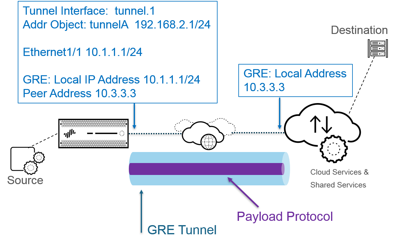
Create a GRE tunnel when you want to direct packets that are destined for an IP address to take a certain point-to-point path, for example to a cloud-based proxy or to a partner network. The packets travel through the GRE tunnel (over a transit network such as the internet) to the cloud service while on their way to the destination address. This enables the cloud service to enforce its services or policies on the packets.
The following figure is an example of a GRE tunnel connecting the firewall across the internet to a cloud service.
For better performance and to avoid single points of failure, split multiple connections to the firewall among multiple GRE tunnels rather than use a single tunnel. Each GRE tunnel needs a tunnel interface.
When the firewall allows a packet to pass (based on a policy match) and the packet egresses to a GRE tunnel interface, the firewall adds GRE encapsulation; it doesn’t generate a session. The firewall does not perform a Security policy rule lookup for the GRE-encapsulated traffic, so you don’t need a Security policy rule for the GRE traffic that the firewall encapsulates. However, when the firewall receives GRE traffic, it generates a session and applies all policies to the GRE IP header in addition to the encapsulated traffic. The firewall treats the received GRE packet like any other packet. Therefore:
- If the firewall receives the GRE packet on an interface that has the same zone as the tunnel interface associated with the GRE tunnel (for example, tunnel.1), the source zone is the same as the destination zone. By default, traffic is allowed within a zone (intrazone traffic), so the ingress GRE traffic is allowed by default.
- However, if you configured your own intrazone Security policy rule to deny such traffic, you must explicitly allow GRE traffic.
- Likewise, if the zone of the tunnel interface associated with the GRE tunnel (for example, tunnel.1) is a different zone from that of the ingress interface, you must configure a Security policy rule to allow the GRE traffic.
Because the firewall encapsulates the tunneled packet in a GRE packet, the additional 24 bytes of GRE header automatically result in a smaller Maximum Segment Size (MSS) in the maximum transmission unit (MTU). If you don’t change the IPv4 MSS Adjustment Size for the interface, the firewall reduces the MTU by 64 bytes by default (40 bytes of IP header + 24 bytes of GRE header). This means if the default MTU is 1,500 bytes, the MSS will be 1,436 bytes (1,500 - 40 - 24 = 1,436). If you configure an MSS Adjustment Size of 300 bytes, for example, the MSS will be only 1,176 bytes (1,500 - 300 - 24 = 1,176).
The firewall does not support routing a GRE or IPSec tunnel to a GRE tunnel, but you can route a GRE tunnel to an IPSec tunnel. Additionally:
- A GRE tunnel does not support QoS.
- The firewall does not support a single interface acting as both a GRE tunnel endpoint and a decryption broker.
- GRE tunneling does not support NAT between GRE tunnel endpoints.
If you need to connect to another vendor’s network, we recommend you set up an IPSec tunnel , not a GRE tunnel; you should use a GRE tunnel only if that is the only point-to-point tunnel mechanism that the vendor supports. You can also enable GRE over IPSec if the remote endpoint requires that ( Add GRE Encapsulation ). Add GRE encapsulation in cases where the remote endpoint requires traffic to be encapsulated within a GRE tunnel before IPSec encrypts the traffic. For example, some implementations require multicast traffic to be encapsulated before IPSec encrypts it. If this is a requirement for your environment and the GRE tunnel and IPSec tunnel share the same IP address, Add GRE Encapsulation when you set up the IPSec tunnel.
If you aren’t planning to terminate a GRE tunnel on the firewall, but you want the ability to inspect and control traffic passing through the firewall inside a GRE tunnel, don’t create a GRE tunnel. Instead, perform Tunnel Content Inspection of GRE traffic. With tunnel content inspection, you are inspecting and enforcing policy on GRE traffic passing through the firewall, not creating a point-to-point, logical link for the purpose of directing traffic.
Create a GRE Tunnel
Create a Generic Routing Encapsulation (GRE) tunnel to connect two endpoints in a point-to-point, logical link.
- Create a tunnel interface.
- Select NetworkInterfacesTunnel .
- Add a tunnel and enter the tunnel Interface Name followed by a period and a number (range is 1 to 9,999). For example, tunnel.1 .
- On the Config tab, assign the tunnel interface to a Virtual Router .
- Assign the tunnel interface to a Virtual System if the firewall supports multiple virtual systems.
- Assign the tunnel interface to a Security Zone .
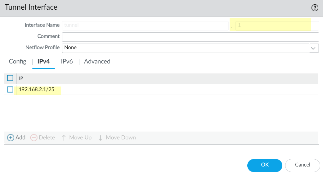
- Assign an IP address to the tunnel interface. (You must assign an IP address if you want to route to this tunnel or monitor the tunnel endpoint.) Select IPv4 or IPv6 or configure both.
This address and the corresponding address of the tunnel interface of the peer should be on the same subnet because it is a point-to-point, logical link.
- ( IPv4 only ) On the IPv4 tab, Add an IPv4 address, select an address object, or click New Address and specify the Type of address and enter it. For example, enter 192.168.2.1 .
- ( IPv6 only ) On the IPv6 tab, Enable IPv6 on the interface .
- For Interface ID , select EUI-64 (default 64-bit Extended Unique Identifier) .
- Add a new Address , select an IPv6 address object, or click New Address and specify an address Name . Enable address on interface and click OK .
- Select Type of address and enter the IPv6 address or FQDN and click OK to save the new address.
- Select Enable address on interface and click OK .
- Click OK .
- Create a GRE tunnel to force packets to traverse a specific point-to-point path.
- Select NetworkGRE Tunnels and Add a tunnel by Name .
- Select the Interface to use as the local GRE tunnel endpoint (source interface), which is an Ethernet interface or subinterface, an Aggregate Ethernet (AE) interface, a loopback interface, or a VLAN interface.
- Select the Local Address to be IP and select the IP address of the interface you just selected.
- Enter the Peer Address , which is the IP address of the opposite endpoint of the GRE tunnel.
- Select the Tunnel Interface that you created in Step 1. (This identifies the tunnel when it is the egress Interface for routing.)
- Enter the TTL for the IP packet encapsulated in the GRE packet (range is 1 to 255; default is 64).
- Select Copy ToS Header to copy the Type of Service (ToS) field from the inner IP header to the outer IP header of the encapsulated packets to preserve the original ToS information. Select this option if your network uses QoS and depends on the ToS bits for enforcing QoS policies.
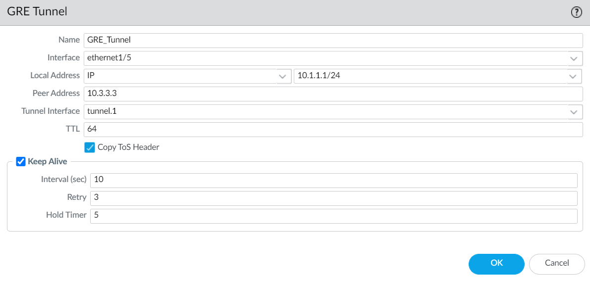
- ( Best Practice ) Enable the Keep Alive function for the GRE tunnel.
If Keep Alive is enabled, by default it takes three unreturned keepalive packets (Retries) at 10-second intervals for the GRE tunnel to go down and it takes five Hold Timer intervals at 10-second intervals for the GRE tunnel to come back up.
- Select Keep Alive to enable the keepalive function for the GRE tunnel (default is disabled).
- ( Optional ) Set the Interval (sec) (in seconds) between keepalive packets that the local end of the GRE tunnel sends to the tunnel peer. This is also the interval that, when multiplied by the Hold Timer , is the length of time that the firewall must see successful keepalive packets before the GRE tunnel comes back up (range is 1 to 50; default is 10). Setting an interval too small will cause many keepalive packets that might be unnecessary in your environment and will require extra bandwidth and processing. Setting an interval too large can delay failover because error conditions might not be identified immediately.
- ( Optional ) Enter the Retry setting, which is the number of intervals that keepalive packets are not returned before the firewall considers the tunnel peer down (range is 1 to 255; default is 3). When the tunnel is down, the firewall removes routes associated with the tunnel from the forwarding table. Configuring a retry setting helps avoid taking measures on a tunnel that is not really down.
- ( Optional ) Set the Hold Timer , which is the number of Intervals that keepalive packets are successful, after which the firewall re-establishes communication with the tunnel peer (range is 1 to 64; default is 5).
- Click OK .
- Configure a routing protocol or static route to route traffic to the destination by way of the GRE tunnel. For example, Configure a Static Route to the network of the destination server and specify the egress Interface to be the local tunnel endpoint (tunnel.1). Configure the Next Hop to be the IP address of the tunnel at the opposite end. For example, 192.168.2.3.
- Commit your changes.
- Configure the opposite end of the tunnel with its public IP address, its local and peer IP addresses (that correspond to the peer and local IP addresses, respectively, of the GRE tunnel on the firewall), and its routing protocol or static route.
- Verify that the firewall can communicate with the tunnel peer over the GRE tunnel.
- Access the CLI .
- > ping source 192.168.2.1 host 192.168.2.3
How To create GRE tunnel over IPSec tunnel using loopback
interface.
Environment
- Palo Alto Firewalls
- PAN-OS PANOS- 9.1, 10.1, 10.2, 11.0 and 11.1
- IPSec Tunnel
- GRE Tunnel
Procedure
The configuration is explained using the following topology
- IPSec Tunnel is configured between FW-1 and FW-2. The tunnel interface is tunnel.1
- GRE Tunnel is configured over the existing IPSEC tunnel. The tunnel interface is tunnel.2
- Firewall-1 192.168.1.1 <--------ipsec (tunnel.1)--------------> Firewall2 192.168.1.2
- loopback 10.20.20.1 <-------- GRE (tunnel.2) -------------> loopback 10.20.20.1
- Configure IPSec between the two Firewalls using the external IP address. Refer to the knowledge article " How to configure IPSec tunnel "
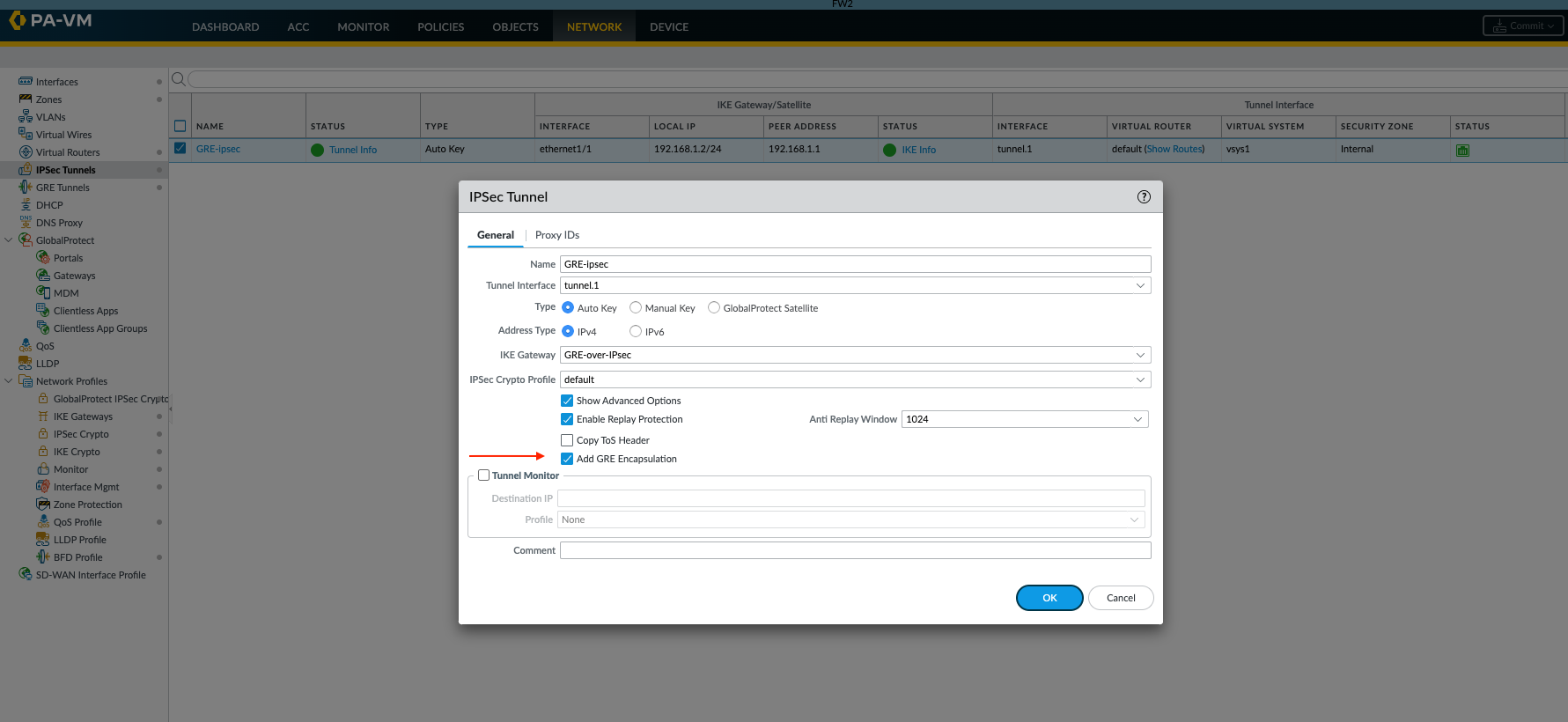
- In the advanced option ensure " Add GRE Encapsulation " is enabled. Here tunnel.1 interface is used for the IPsec tunnel, configure remote side with opposite IP address.
GUI: Network > IPsec Tunnels > (tunnel name) > Click on "Show Advanced Options" and click on "Add GRE encapsulation"
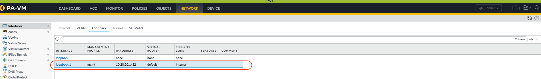
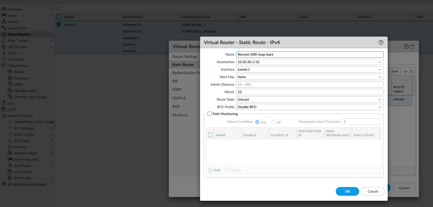
- Configure loopback interface and create a static route in both sites to reach that loopback IP address via IPsec tunnel ( in this example its tunnel.1 interface). In this example loopback IP address is 10.20.20.1/32 and the remote loopback IP address is 10.30.30.1/32. Static route is created via a tunnel.1 (ipsec) to reach 10.30.30.1/32
GUI:
Network > Virtual Routers > (name of
VR)> Static Routes > Add
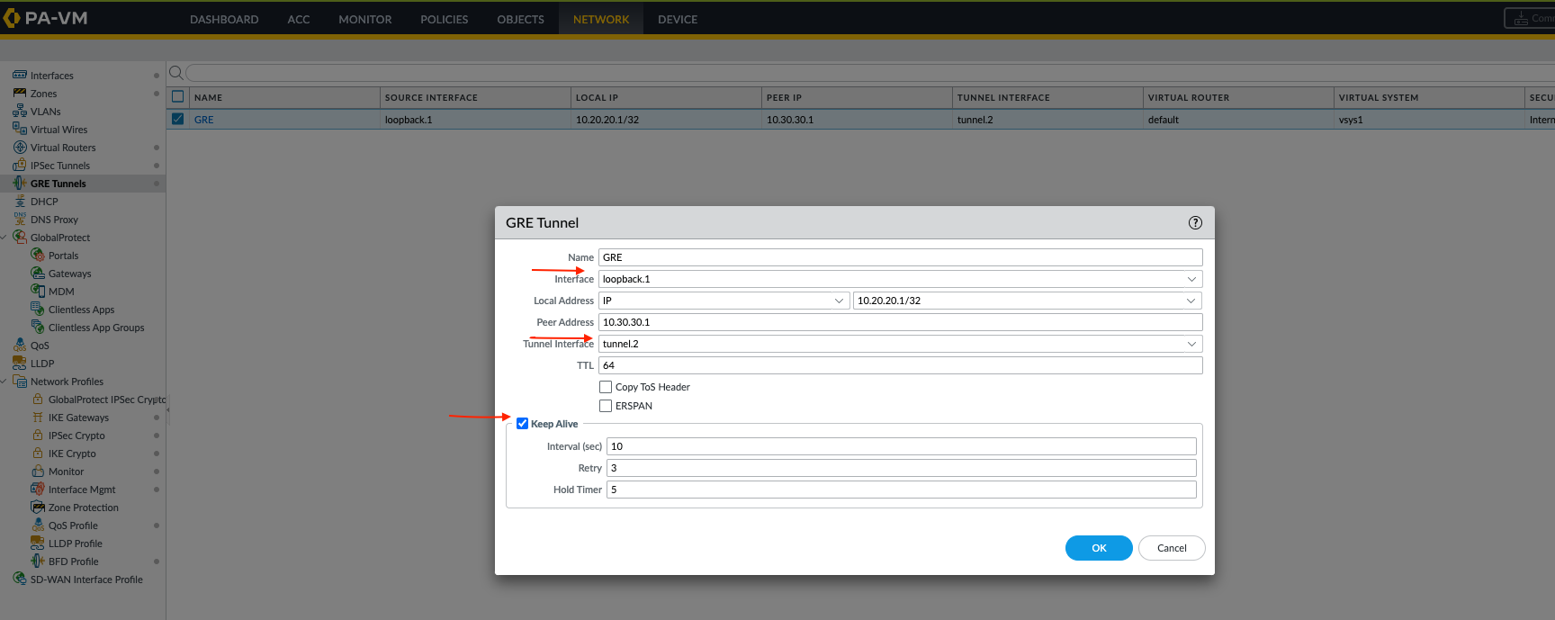
- Create a tunnel interface for GRE and create GRE tunnel using loopback as local IP address and peer IP address and assign tunnel interface (in this example it's tunnel.2) on both sides, make sure to enable GRE keepalive which is being routed over IPsec tunnel.
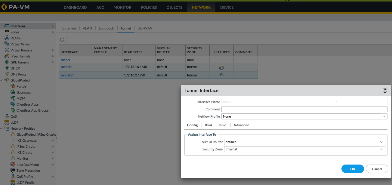
GUI:
Network > GRE Tunnels > Add
- Confirm the GRE tunnel is up by running the command "show interface tunnel <no>"
adminn@PA-FW1> show interface tunnel.2
--------------------------------------------------------------------------------
Name: tunnel.2, ID: 258
Operation mode: layer3
Virtual router default
Interface MTU 1500
Interface IP address: 172.16.2.1/30
Interface management profile: N/A
Service configured:
Zone: Internal, virtual system: vsys1
Adjust TCP MSS: no
Ignore IPv4 DF: no
Policing: no
Proxy protocol: no
--------------------------------------------------------------------------------
GRE tunnel name: GRE
tunnel interface state: Up
disabled: False
erspan: False
copy-tos: False
keep alive enabled: True
local-ip: 10.20.20.1
peer-ip: 10.30.30.1
- Add a route to reach remote networks over GRE tunnel
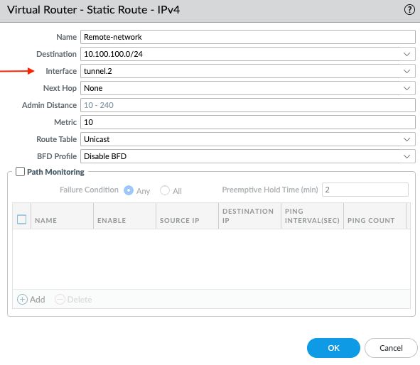
- Verify the connectivity by pinging the remote side. To confirm the session id can be checked ("show session all" and check one of the ping). This will show traffic is traversing over GRE tunnel over IPsec
adminn@PA-FW1> show session id 7632
Session 7632
c2s flow:
source: 10.10.10.1 [Internal]
dst: 10.100.100.1
proto: 1
sport: 26067 dport: 1
state: INIT type: FLOW
src user: unknown
dst user: unknown
s2c flow:
source: 10.100.100.1 [Internal]
dst: 10.10.10.1
proto: 1
sport: 1 dport: 26067
state: INIT type: FLOW
src user: unknown
dst user: unknown
.. <Output Omitted> ...
session traverses tunnel : True
session terminate tunnel : False
captive portal session : False
ingress interface : ethernet1/2
egress interface : tunnel.2
session QoS rule : N/A (class 4)
end-reason : aged-out