Palo Alto Networks Layer 2 Interfaces: A Deep Dive for PCNSE
Layer 2 (L2) interfaces on Palo Alto Networks Next-Generation Firewalls (NGFWs) allow the firewall to be deployed as a "bump in the wire" or a transparent bridge. This means the firewall can be inserted into an existing network segment, typically between a switch and a router or between two switches, without requiring any IP address changes on the surrounding network devices or end hosts. This deployment mode is invaluable for adding robust security inspection capabilities with minimal network disruption.
Core Concepts of Layer 2 Interfaces in PAN-OS
In a Layer 2 deployment, the Palo Alto Networks firewall forwards Ethernet frames based on their destination MAC addresses. It learns MAC addresses on its connected interfaces and builds a MAC address table, much like a standard Layer 2 switch. However, unlike a simple switch, the firewall inspects all permitted traffic passing through it using its full suite of security services, including App-ID, Content-ID, User-ID, Threat Prevention, and WildFire.
- No IP Address: Layer 2 interfaces do not have IP addresses assigned to them. Consequently, they do not participate in IP routing.
- Security Zones: Each Layer 2 interface (or subinterface) must be assigned to a Security Zone. Security policies are then defined to control traffic flow between these zones.
- MAC Address Learning: The firewall dynamically learns MAC addresses of connected devices and populates a MAC table for forwarding decisions.
- Transparent Operation: End devices and other network equipment are unaware of the firewall's presence from an IP routing perspective.
When to Use Palo Alto Networks Layer 2 Interfaces
Layer 2 interfaces are ideal for several scenarios within the Palo Alto Networks ecosystem:
- Transparent Security Insertion: The most common use case. Add a firewall to an existing network segment (e.g., between an internal switch and the perimeter router, or in front of a critical server segment) without re-addressing or changing routing. This allows for rapid deployment of advanced security.
- Securing VLANs: Inspect inter-VLAN traffic that is already being trunked through the network. By configuring L2 subinterfaces, the firewall can selectively inspect traffic for specific VLANs.
- Internal Segmentation Gateway (Transparent Mode): Place a firewall between internal network segments (e.g., user LAN and database LAN on the same IP subnet initially) to enforce security policies without altering the L3 topology.
- Proof of Concepts (PoCs): Quickly deploy a firewall to demonstrate its security capabilities without extensive network changes.
- Phased Deployments: Insert the firewall in L2 mode initially to provide immediate threat prevention, then potentially migrate to L3 mode later for more advanced routing capabilities if required.
- Protecting Server Farms: Secure servers within a single broadcast domain by placing the firewall in L2 mode in front of the server switches.
Configuring Layer 2 Interfaces in PAN-OS
Configuration is typically done via the PAN-OS web interface or CLI.
Using the PAN-OS Web Interface:
- Navigate to Network > Interfaces > Ethernet .
-
Select the physical interface you want to configure (e.g.,
ethernet1/1). -
In the configuration window:
- Interface Name: Keep the default or assign a descriptive name.
- Comment: Add a description (e.g., "L2 Bridge to Internal LAN").
- Interface Type: Select Layer 2 from the dropdown.
- NetFlow Profile: (Optional) Assign a NetFlow profile if you want to export flow data for traffic traversing this interface. Note that the firewall itself needs an L3 interface with IP connectivity to the NetFlow collector.
- Link Speed/Duplex: Typically leave as 'auto'.
-
Navigate to the
Layer 2
tab (this tab appears after selecting Layer 2 as the interface type).
- Security Zone: Click Add and select or create a new Security Zone. This is mandatory for policy enforcement. For a simple two-port bridge, you'd typically have two L2 interfaces in different zones (e.g., 'L2-Trust' and 'L2-Untrust').
- LLDP Profile: (Optional) Enable LLDP if needed for network discovery.
- Click OK .
- Commit the changes.
GUI Path: Network > Interfaces > Ethernet > Select Interface > Interface Type: Layer 2
Using the PAN-OS CLI:
configure
set network interface ethernet ethernet1/1 layer2 zone L2-Inside
set network interface ethernet ethernet1/2 layer2 zone L2-Outside
set network interface ethernet ethernet1/1 layer2 lldp enable no  // Example to disable LLDP
commit
VLANs and Layer 2 Subinterfaces on Palo Alto Networks Firewalls
Palo Alto Networks firewalls fully support IEEE 802.1Q VLAN tagging on Layer 2 interfaces through the use of subinterfaces. Each L2 subinterface is associated with a specific VLAN ID and functions as a distinct logical interface. This allows the firewall to inspect and apply policies to traffic segregated by VLANs.
Configuring Layer 2 Subinterfaces:
- Ensure the parent physical interface is configured as Layer 2 .
- In the parent interface's configuration window ( Network > Interfaces > Ethernet ), click Add Subinterface .
-
In the subinterface configuration window:
-
Interface Name:
Automatically generated (e.g.,
ethernet1/1.10). -
Tag:
Enter the VLAN ID (e.g.,
10for VLAN 10). - Comment: (Optional) Add a description.
- Security Zone: Assign a Security Zone. Each subinterface can be in a different zone, allowing granular policy control between VLANs.
- NetFlow Profile, LLDP Profile: Optional, similar to parent interface.
- MTU: Inherits from the physical interface by default, but can be set manually.
-
Interface Name:
Automatically generated (e.g.,
- Click OK .
- Repeat for additional VLANs/subinterfaces as needed.
- Commit the changes.
GUI Path: Network > Interfaces > Ethernet > Select Parent Interface > Add Subinterface
configure
set network interface ethernet ethernet1/1 layer2  // Parent must be L2
set network interface ethernet ethernet1/1.10 layer2 vlan 10 zone VLAN10-Zone
set network interface ethernet ethernet1/1.20 layer2 vlan 20 zone VLAN20-Zone
commit
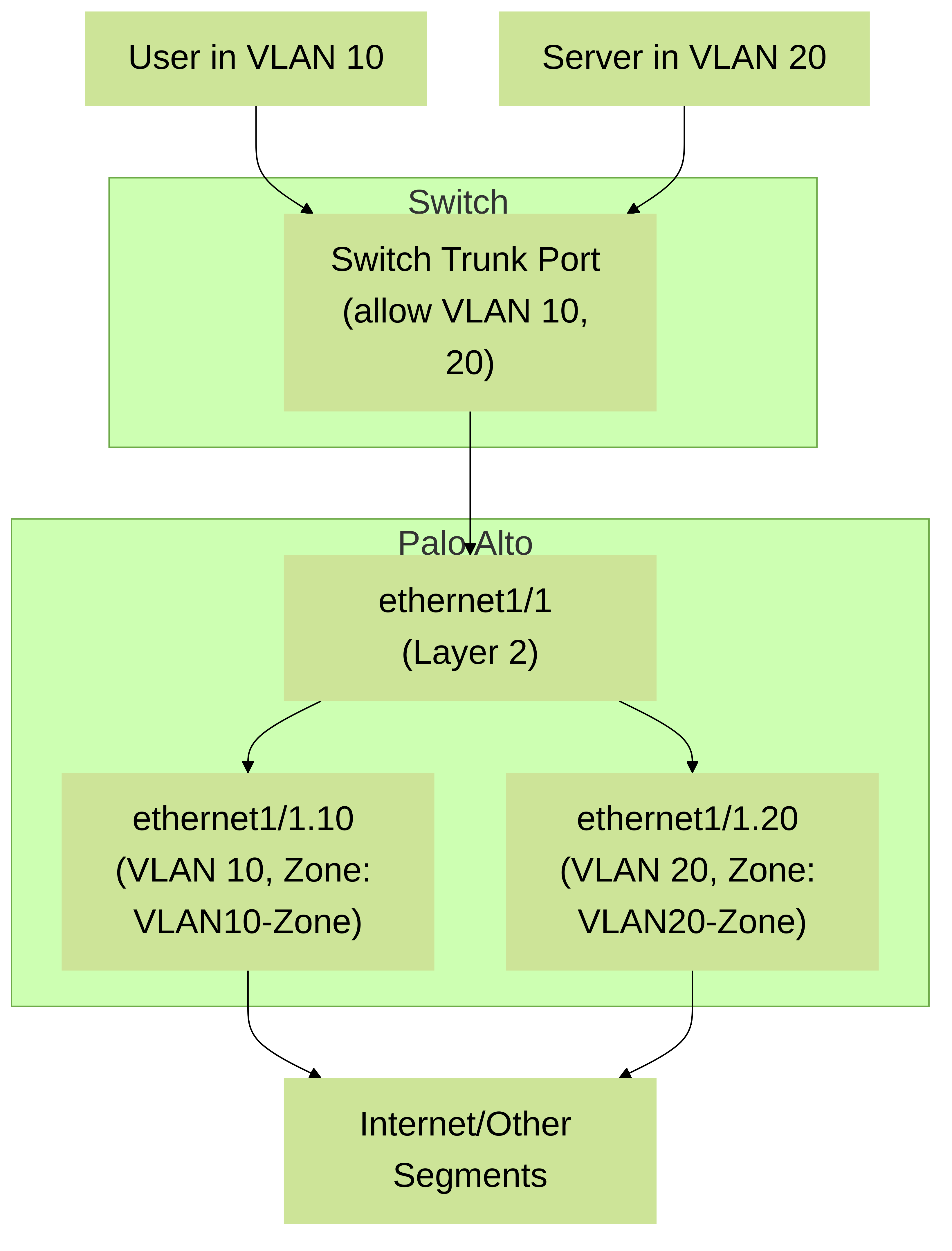
Palo Alto Networks Firewall with Layer 2 subinterfaces connected to a switch trunk port. Traffic for VLAN 10 is processed by
ethernet1/1.10
and traffic for VLAN 20 by
ethernet1/1.20
, each assigned to potentially different Security Zones for policy enforcement.
Traffic Flow and MAC Learning in Layer 2 Mode
When a frame arrives on a Layer 2 interface:
- The firewall checks if the source MAC address is already in its MAC table for that input interface's broadcast domain. If not, it learns the MAC address and associates it with the ingress interface and VLAN (if applicable).
- If it's a subinterface, the VLAN tag is checked.
-
The firewall looks up the destination MAC address in its MAC table.
- Known MAC: If found, the frame is forwarded to the associated egress interface.
- Unknown MAC (Unicast Flood): If the destination MAC is not in the table, the frame is flooded out of all other Layer 2 interfaces and subinterfaces within the same broadcast domain (i.e., same VLAN, or all L2 interfaces if no VLANs are involved on those specific interfaces). This does NOT cross security zone boundaries without a policy.
- Broadcast/Multicast: Broadcast frames (e.g., ARP requests) and multicast frames are flooded to all other Layer 2 interfaces/subinterfaces in the same broadcast domain.
- Security Policy Evaluation: Crucially, before forwarding, if the ingress and intended egress interfaces are in different Security Zones, the traffic is subject to Security Policy lookup. If they are in the same zone, intra-zone policies apply (default deny, explicit allow needed). App-ID and other security inspections occur if the policy permits the traffic.
Spanning Tree Protocol (STP) Considerations
Failure to correctly configure STP on the switches in a topology involving L2 firewalls can lead to broadcast storms and network instability. Best practices include:
- Ensuring STP is enabled and functioning correctly on all connected switches.
-
On switch ports connected to firewall Layer 2 interfaces:
- Consider enabling BPDU Guard if the port is not expected to receive BPDUs from another switch (i.e., if the firewall is an edge device in that L2 segment). If BPDUs are unexpectedly received, BPDU Guard will shut down the port, preventing a loop.
- Alternatively, ensure the port is part of a robust STP topology. Some designs might use Root Guard to prevent the switch port connected to the firewall from becoming an STP root path.
- Using features like Cisco's PortFast (or equivalent) is generally *not recommended* for ports connected to other bridging devices like a firewall in L2 mode, as PortFast transitions the port to forwarding state immediately and disables STP on it. This is typically for host ports. However, if you are absolutely certain no loops can be formed through the firewall, it might be considered with caution. The key is that BPDUs *must* be allowed to pass through the firewall if it's in-line between switches that need to run STP.
- Carefully plan physical cabling to avoid creating redundant paths that STP cannot resolve due to the firewall's non-participation.
Illustrates a Palo Alto Networks firewall with Layer 2 interfaces between two switches. The firewall forwards BPDUs but doesn't participate in STP. Switches 1 and 2 must manage the STP domain and prevent loops, especially if a direct link (Link C) exists between them.
High Availability (HA) with Layer 2 Interfaces
Palo Alto Networks firewalls in an HA cluster (Active/Passive or Active/Active) can utilize Layer 2 interfaces. Key considerations:
- Configuration Sync: L2 interface configurations, including subinterfaces and security zones, are synchronized from the active to the passive firewall.
- Path Monitoring: Link and Path Monitoring can be configured for L2 interfaces to trigger HA failover if connectivity is lost.
- MAC Address Table: In an HA failover, the newly active firewall will take over. It may issue Gratuitous ARP (GARP) if it has L3 interfaces, but for pure L2 forwarding, the MAC tables on connected switches will need to update to reflect the MAC addresses now reachable via the newly active firewall's ports. This usually happens quickly as traffic flows.
- Session Sync: Active sessions are synchronized, allowing for stateful failover even for traffic passing through L2 interfaces.
High Availability (HA) deployment with Palo Alto Networks firewalls using Layer 2 interfaces. Both firewalls connect to the same L2 segments. Configuration and session state are synchronized for seamless failover.
Feature Support on Palo Alto Networks Layer 2 Interfaces
While Layer 2 interfaces lack IP-based functionalities, they support a wide range of Palo Alto Networks security services:
| Feature | Support on L2 Interfaces | Palo Alto Networks Specific Notes |
|---|---|---|
| App-ID | Yes | Full application identification and control based on signatures and heuristics. Policies can allow/deny/scan specific applications. |
| User-ID | Yes | Integrates with directory services (AD, LDAP, etc.) to enforce user-based policies, even in L2 mode. The firewall needs L3 connectivity for User-ID agent communication. |
| Content-ID (Threat Prevention, URL Filtering, File Blocking) | Yes | Includes Antivirus, Anti-Spyware, Vulnerability Protection, URL Filtering, and File Blocking profiles applied to security policies. |
| WildFire | Yes | Forward unknown files and links for analysis. Requires WildFire cloud connectivity (typically via a management interface or other L3 interface). |
| SSL Decryption (Forward Proxy) | Yes | Can decrypt and inspect SSL/TLS traffic passing through L2 interfaces. Requires certificate deployment and configuration. |
| DoS Protection | Yes | DoS Protection profiles can be applied to zones or interfaces to mitigate denial-of-service attacks. |
| QoS (Quality of Service) | Yes | QoS policies can be applied to traffic egressing Layer 2 interfaces to prioritize applications and manage bandwidth. |
| LLDP | Yes | Link Layer Discovery Protocol can be enabled on L2 interfaces. |
| Aggregate Ethernet (LAG/LACP) | Yes | Physical L2 interfaces can be bundled into an AE group configured in L2 mode. |
| NAT | No | NAT is a Layer 3 function requiring IP addresses. Use a Layer 3 interface or VLAN Interface (SVI) for NAT. |
| Routing Protocols (OSPF, BGP, etc.) | No | Routing is a Layer 3 function. L2 interfaces do not participate in dynamic routing. |
| VPN (IPsec/SSL) | No | VPN termination requires Layer 3 interfaces with IP addresses. |
| DHCP Server/Relay | No | These services require an IP address on the interface. |
| GlobalProtect Gateway/Portal | No | Requires Layer 3 interfaces. |
Aggregate Ethernet (AE) with Layer 2 Interfaces
Palo Alto Networks firewalls support Link Aggregation Groups (LAGs) using Aggregate Ethernet (AE) interfaces. Physical Layer 2 interfaces can be grouped into an AE interface, which itself is then configured as Layer 2. This provides increased bandwidth and link redundancy.
- LACP Support: PAN-OS supports LACP (IEEE 802.3ad/802.1AX) for dynamic negotiation of link aggregation with connected switches. Static aggregation is also possible.
-
Configuration:
-
Create an AE interface (e.g.,
ae1). - Configure the AE interface type as Layer 2 . Assign it a security zone.
- If using LACP: configure LACP parameters (mode: active/passive, rate: fast/slow, etc.) on the AE interface.
- Assign physical Ethernet interfaces to the AE group. These physical interfaces must not have any prior L2/L3 configuration (set them to "None" type first if needed).
-
Create an AE interface (e.g.,
- L2 subinterfaces can also be configured on an AE interface that is in L2 mode, allowing VLAN tagging over the aggregated link.
Palo Alto Networks firewall with an Aggregate Ethernet (AE) interface in Layer 2 mode, bundled with physical interfaces
eth1/1
and
eth1/2
. This AE interface connects to a corresponding LAG (Port-Channel) on a switch, providing increased throughput and redundancy for L2 traffic.
Layer 2 vs. Virtual Wire (VWire) Interfaces
Both Layer 2 and Virtual Wire (VWire) interfaces offer transparent firewalling capabilities, but they have distinct characteristics and use cases:
| Feature | Layer 2 Interface Mode | Virtual Wire Interface Mode |
|---|---|---|
| Concept | Acts like a bridge or switch, forwarding based on MAC addresses. Can connect multiple segments. | Acts like a "bump on the wire" between exactly two interfaces. Simpler pass-through. |
| Number of Interfaces | Can involve multiple physical interfaces (each in L2 mode) forming a larger bridge group, or bridging between subinterfaces on a single physical interface. | Strictly two physical interfaces paired together as a VWire object. |
| MAC Learning | Yes, builds a MAC table. | No MAC learning in the traditional sense. Frames entering one VWire interface are typically forwarded out the other if allowed by policy. (Note: Some MAC learning occurs for features like HA MAC masquerading, but not for general forwarding decisions within the VWire itself.) |
| VLAN Handling | Supports L2 subinterfaces for 802.1Q VLAN tagging. Can inspect and switch traffic between different VLANs. | Can pass tagged and untagged traffic. VWire subinterfaces can be created to associate specific VLAN tags with different security zones, allowing policy per VLAN over the VWire. |
| Spanning Tree Protocol | Does not participate; forwards BPDUs. | Does not participate; forwards BPDUs. |
| Use Case Complexity | More flexible for bridging multiple segments or VLANs, creating more complex transparent topologies. | Simpler for point-to-point transparent insertion on a single link. |
| Security Zones | Each L2 interface or subinterface is assigned to a security zone. | The VWire object itself is assigned to security zones (one for each "side" or direction if needed, or they can share zones). VWire subinterfaces can have their own zones. |
Troubleshooting Layer 2 Deployments on PAN-OS
Common troubleshooting steps for L2 interface issues:
-
Verify Physical Connectivity:
Check link status, speed/duplex settings on both the firewall and connected switch.
show interface ethernet1/1
-
Check Interface Configuration:
Ensure interfaces are correctly set to Layer 2, assigned to security zones, and subinterfaces have correct VLAN tags.
show running-config interface ethernet ethernet1/1
-
Inspect MAC Address Table:
Verify the firewall is learning MAC addresses correctly.
show mac all
show mac interface ethernet1/1.10
-
Examine Security Policies:
Ensure policies allow traffic between the relevant source and destination zones. Check traffic logs for policy hits, denies, or unexpected behavior.
Monitor > Traffic Log
- Check VLAN Configuration: Ensure VLAN tags match between the firewall subinterfaces and the switch trunk configuration. Verify allowed VLANs on trunks.
-
Spanning Tree Protocol Issues:
If intermittent connectivity or broadcast storms occur, investigate STP on connected switches. The firewall will not show STP state.
Gotcha! (Palo Alto Networks): A common issue is a mismatch in VLAN tagging or trunk configuration on the switch side. Use `tcpdump` or packet captures on the firewall (or SPAN/mirror ports on the switch) to verify tags.
-
Interface Counters:
Check for errors, drops, or unusual packet counts.
show counter interface ethernet1/1
-
Debug Flow Basic:
For deeper packet processing insight (use with caution in production).
debug flow basic
// (Reproduce issue)
show counter global filter packet-filter yes delta yes
// (Clear filter and stop debug)
clear debug flow all
debug flow basic clear
- ARP: While L2 interfaces don't have IPs, ARP issues on connected L3 devices can impact traffic flowing *through* the firewall. Ensure end devices can ARP for their gateways.
Conclusion
Palo Alto Networks Layer 2 interfaces provide a powerful and flexible way to deploy next-generation security capabilities transparently within existing network infrastructures. By understanding their configuration, operational nuances (especially regarding STP and VLANs), and how security services are applied, network security engineers can effectively leverage L2 mode to enhance security posture with minimal disruption. For the PCNSE exam, a thorough grasp of L2 concepts, configuration, and limitations is essential.