 Mastering Palo Alto Networks Layer 2 Interfaces for PCNSE
Palo Alto Networks Next-Generation Firewalls (NGFWs) offer versatile deployment options, including the ability to configure interfaces in Layer 2 (L2) mode. Operating at the data link layer (OSI Layer 2), these interfaces allow the firewall to function like a transparent bridge or switch, forwarding frames based on MAC addresses. This mode is invaluable for seamlessly integrating a Palo Alto Networks firewall into an existing network without requiring IP address changes, while still providing robust security inspection. Understanding Layer 2 interfaces is critical for network engineers and for success on the Palo Alto Networks Certified Network Security Engineer (PCNSE) exam.
🚀 Core Concepts of Layer 2 Interfaces in PAN-OS
When an interface on a Palo Alto Networks firewall is configured in Layer 2 mode, it strips any IP address configuration and operates by examining Ethernet headers to make forwarding decisions.
- Transparent Bridging: The firewall invisibly inspects traffic passing through it. Devices on either side of the firewall segment are unaware of its presence from an IP routing perspective.
-
MAC Address Learning:
PAN-OS maintains a MAC address table for each Layer 2 interface and VLAN. It learns source MAC addresses from incoming frames and uses destination MAC addresses to forward frames. You can view this table using the CLI command:
show mac all
- Broadcast and Multicast Handling: Broadcast and multicast frames are flooded out of all Layer 2 interfaces belonging to the same VLAN/broadcast domain, except the one on which they were received.
- Security Zones: Crucially, each Layer 2 interface or subinterface must be assigned to a Security Zone. Security policies are then applied to control traffic flowing between these zones, enabling full App-ID, User-ID, and Content-ID inspection.
- VLAN Tagging (IEEE 802.1Q): Layer 2 interfaces can process VLAN-tagged traffic. This is achieved by creating Layer 2 subinterfaces, where each subinterface is assigned a specific VLAN ID.
✅ Key Use Cases for Layer 2 Interfaces
-
Seamless (Transparent) Deployment:
This is a primary advantage. A Palo Alto Networks firewall can be inserted into an existing network segment (e.g., between a switch and a router, or between two switches) without any changes to the IP addressing scheme of connected devices. This minimizes network disruption and simplifies initial deployment, allowing organizations to quickly gain visibility and security for specific segments.
Example Scenario: Placing a PA-Series firewall in L2 mode in front of a critical server farm to inspect all traffic to and from the servers without re-IPing the servers or altering the existing routing infrastructure.
-
Inline Security for Same-Subnet Traffic:
Provide full threat prevention (Antivirus, Anti-Spyware, Vulnerability Protection), WildFire analysis, URL Filtering, and Application Control (App-ID) for traffic flowing between devices within the same IP subnet. For instance, if two departments are on the same VLAN but need to be logically segmented and inspected, L2 interfaces with appropriate security zones can achieve this.
-
VLAN Segmentation and Inter-VLAN Security (within L2 domain):
Use Layer 2 subinterfaces to handle multiple VLANs on a single physical interface (trunk port). Each subinterface can be assigned to a different security zone, allowing granular security policies to be enforced for traffic within and between these VLANs as it passes through the firewall. Note that routing between these VLANs (inter-VLAN routing) would typically still require Layer 3 interfaces (like VLAN interfaces/SVIs) or an external router if the firewall is purely in L2 mode for those VLANs.
Palo Alto Networks Context: This is common in scenarios where you want to inspect east-west traffic within a data center or a campus LAN segment.
-
Internal Network Segmentation Gateway (Transparent Mode):
When a full routed deployment is not immediately feasible or desired for certain internal segments, an L2 firewall can act as a transparent security gateway between internal network segments, enforcing policies based on zones tied to different VLANs.
⚙️ Configuration Steps in PAN-OS
Configuring a Layer 2 interface involves setting the interface type, assigning it to a security zone, and optionally configuring subinterfaces for VLANs. This can be done via the PAN-OS web interface (GUI) or the command-line interface (CLI).
Using the PAN-OS Web Interface (GUI):
-
Navigate to Interfaces:
- Go to Network > Interfaces > Ethernet .
-
Select the physical interface you wish to configure (e.g.,
ethernet1/1).
-
Set Interface Type to Layer 2:
- In the interface configuration window, change the Interface Type dropdown to Layer2 .
- Caption: Example of selecting Layer2 as Interface Type in PAN-OS GUI.

-
Assign to Security Zone:
- Under the Config tab (which appears after selecting Layer2), select an existing Security Zone from the dropdown or click "New Security Zone" to create one. All traffic passing through this interface will be associated with this zone.
- For L2 interfaces, ensure "Enable User Identification" is checked on the zone if User-ID is required.
-
Configure VLANs (Optional - using Subinterfaces):
-
If the physical Layer 2 interface will connect to a switch trunk port and handle multiple VLANs:
- Click Add Subinterface .
-
Enter a numerical tag for the subinterface (e.g.,
10for subinterfaceethernet1/1.10). This number is locally significant but often matches the VLAN ID for clarity. -
In the
Tag
field, enter the
VLAN ID
(e.g.,
10for VLAN 10). - Assign this subinterface to a Security Zone (can be the same or different from other subinterfaces or the parent L2 interface).
- Repeat for each VLAN.
- If the interface is an access port for a single VLAN, you can optionally assign a VLAN object directly to the physical Layer 2 interface if it's intended to only pass traffic for that VLAN (though subinterfaces are more common for explicit tagging). Typically, for untagged traffic on an L2 port, you'd leave the VLAN field as "None" on the physical L2 interface and it would belong to a broadcast domain.
Note: A physical Layer 2 interface itself can be part of a VLAN, or it can act as a trunk carrying multiple tagged VLANs via subinterfaces. If subinterfaces are used, the parent physical L2 interface typically doesn't have a VLAN assigned directly and isn't assigned to a zone itself if all traffic is expected to be tagged and handled by subinterfaces. -
If the physical Layer 2 interface will connect to a switch trunk port and handle multiple VLANs:
-
Advanced Settings (Optional):
- Navigate to the Advanced tab for the Layer 2 interface or subinterface.
- Here you can configure settings like MTU, Link Speed/Duplex, and LLDP Profile.
- For QoS, enable QoS on the physical interface and apply a QoS Profile. QoS policies will then shape egress traffic.
-
Commit Changes:
- Click OK to save the interface configuration.
- Click Commit in the top-right corner of the PAN-OS GUI and then Commit again to apply the changes to the firewall.
Using the PAN-OS Command Line Interface (CLI):
configure
set network interface ethernet ethernet1/1 layer2
set network interface ethernet ethernet1/1 layer2 units ethernet1/1.10 tag 10
set zone L2-Internal network layer2 ethernet1/1
set zone L2-VLAN10 network layer2 ethernet1/1.10
commit
PAN-OS CLI commands to configure
ethernet1/1
as a Layer 2 interface, create a subinterface
ethernet1/1.10
for VLAN 10, and assign them to respective security zones.
🌉 Layer 2 Interfaces and VLANs Deep Dive
Palo Alto Networks firewalls handle VLANs on Layer 2 interfaces primarily through subinterfaces. Each subinterface is tagged with an IEEE 802.1Q VLAN ID and operates as a distinct Layer 2 interface.
- Physical Interface as Trunk: When subinterfaces are configured, the parent physical Layer 2 interface acts like a trunk port, capable of receiving and transmitting frames with different VLAN tags.
-
Subinterface per VLAN:
A separate subinterface is created for each VLAN that needs to be processed by the firewall. For example,
ethernet1/1.10for VLAN 10,ethernet1/1.20for VLAN 20. -
Zone Assignment:
Each subinterface is assigned to a Security Zone. This allows for granular policy enforcement. For example,
ethernet1/1.10could be inZone-VLAN10andethernet1/1.20inZone-VLAN20. Security policies can then control traffic betweenZone-VLAN10andZone-VLAN20. - Untagged Traffic: If the physical Layer 2 interface needs to handle untagged traffic (native VLAN), it can be configured without subinterfaces for that specific VLAN, or by configuring one subinterface without a tag if the switch configuration expects a native VLAN on a trunk (less common on PA firewalls, explicit tagging is preferred). Best practice is generally to tag all VLANs on a trunk.
Palo Alto Networks firewall with
ethernet1/1
as a Layer 2 trunk. Subinterfaces
eth1/1.10
and
eth1/1.20
handle tagged traffic for VLAN 10 (Zone A) and VLAN 20 (Zone B) respectively, allowing policy enforcement between zones.
Distinction: L2 Subinterfaces vs. L3 VLAN Interfaces (SVIs)
It's crucial to distinguish between Layer 2 subinterfaces and Layer 3 VLAN interfaces:
-
Layer 2 Subinterfaces (e.g.,
ethernet1/1.10):- Operate at Layer 2.
- Do not have IP addresses.
- Used to receive and forward tagged traffic on a physical L2 interface.
- Assigned to security zones for policy enforcement within or between L2 domains.
-
Layer 3 VLAN Interfaces (e.g.,
vlan.10):- Operate at Layer 3.
- Have IP addresses, acting as a default gateway for devices in that VLAN.
- Used for inter-VLAN routing.
- Associated with a VLAN ID and one or more Layer 2 or Layer 3 physical/aggregate interfaces that carry traffic for that VLAN.
- Assigned to security zones and virtual routers.
If you need the Palo Alto Networks firewall to route traffic between VLAN 10 and VLAN 20, you would configure Layer 3 VLAN interfaces (e.g.,
vlan.10
with IP 192.168.10.1/24 and
vlan.20
with IP 192.168.20.1/24), assign them to appropriate virtual routers and zones, and ensure the underlying physical interfaces are configured to pass this VLAN traffic (either as L2 trunks with L2 subinterfaces that are then associated with the L3 VLAN interface, or by directly assigning L3 physical interfaces to the VLAN interface). A pure L2 deployment relies on an external router for inter-VLAN routing if not using L3 VLAN interfaces on the firewall itself.
🚦 Traffic Flow in Layer 2 Deployments
Understanding traffic flow is key to troubleshooting and designing L2 deployments.
- Intra-VLAN, Intra-Zone Traffic: If two L2 interfaces (or subinterfaces) are in the same VLAN and the same Security Zone, traffic between them is switched by the firewall based on MAC addresses. By default, intra-zone traffic is implicitly allowed, but can be controlled by an intra-zone security policy rule if needed (default is "allow").
-
Intra-VLAN, Inter-Zone Traffic:
If two L2 interfaces (or subinterfaces) are in the same VLAN but different Security Zones (e.g.,
eth1/1.10inZoneA-VLAN10andeth1/2.10inZoneB-VLAN10), traffic is inspected against security policies allowing traffic betweenZoneA-VLAN10andZoneB-VLAN10. -
Inter-VLAN Traffic (within L2 firewall context):
If traffic is between different VLANs (e.g., VLAN 10 on
eth1/1.10inZoneAand VLAN 20 oneth1/1.20inZoneB), it's inspected based on policies betweenZoneAandZoneB. The firewall acts as a bridge for these distinct broadcast domains, enforcing policy. Actual routing between these IP subnets still needs an L3 gateway (which could be an L3 VLAN interface on the same firewall or an external router). - Hairpinning: If traffic ingresses and egresses the same L2 interface (e.g., from one host to another connected to the same switch, with the firewall also connected to that switch via an L2 interface for that VLAN), the firewall can inspect this traffic if the L2 interface is appropriately zoned and policies are in place. This is useful for securing traffic within the same broadcast domain.
Illustrates traffic flow through a Palo Alto Networks firewall in L2 mode. Client 1 (VLAN 10) communicating with Server (VLAN 20) passes through respective L2 subinterfaces and security zones where policies are enforced. Communication between Client 1 and Client 2 (same VLAN) might also traverse the firewall if it's the path, undergoing inspection.
⚠️ Considerations and Implications for L2 Deployments
-
High Availability (HA):
- Layer 2 interfaces are fully supported in HA (Active/Passive and Active/Active) configurations.
- Both firewalls in the HA pair must have identical Layer 2 interface and subinterface configurations, including zone assignments.
- The firewalls should connect to the same Layer 2 broadcast domains/VLANs on their respective L2 interfaces.
- Path monitoring can be configured for L2 interfaces to trigger failover if the upstream or downstream path fails.
- Session synchronization ensures stateful failover for L2 traffic.
-
PCNSE/PCNSA Exam Note (Palo Alto Networks): For HA with L2 interfaces, ensure L2 connectivity for the HA peers to the same network segments. LACP pre-negotiation for AE interfaces in HA passive state is a key feature to reduce failover time.
-
Spanning Tree Protocol (STP):
- Palo Alto Networks firewalls operating in Layer 2 mode do not participate in STP. They do not generate or process BPDUs to make STP decisions.
- By default, PAN-OS firewalls transparently forward STP BPDUs received on one L2 interface out of other L2 interfaces within the same broadcast domain/VLAN. This allows an external STP topology to function correctly through the firewall.
- Risk: Improper network design around an L2 firewall can lead to switching loops if redundant paths exist without proper STP configuration on the connected switches. The firewall will not break these loops.
- Mitigation: Ensure STP is correctly configured on all connected switches. Use features like STP PortFast (on switch ports connecting to end devices), BPDU Guard/Filter (carefully, on switch ports connecting to the PA firewall if BPDUs are not desired to pass through it, though forwarding is default), and Root Guard on switches.
-
Gotcha! (Palo Alto Networks): Assuming the firewall will break L2 loops is a common mistake. Always design the L2 network with loop prevention mechanisms on the switches.
-
Feature Support and Limitations:
-
Supported:
- Full Security Services: App-ID, User-ID (requires configuration), Content-ID (Threat Prevention, URL Filtering, File Blocking), WildFire.
- SSL Decryption (Forward Proxy).
- Quality of Service (QoS) on physical L2 interfaces (policies apply to egress traffic).
- Zone Protection Profiles.
- Packet Buffer Protection.
- LLDP.
- Logging and Reporting.
- Aggregate Ethernet (LAG/LACP).
-
Not Supported (directly on L2 interfaces):
- IP address assignment.
- Routing protocols (OSPF, BGP, RIP, etc.).
- Network Address Translation (NAT). Traffic must pass to an L3 interface for NAT.
- VPN (IPsec/SSL) termination.
- GlobalProtect Gateway or Portal functionality.
- DHCP Server/Relay (requires L3 interface).
- Policy Based Forwarding (PBF) as it's a routing decision feature.
-
Supported:
-
MTU (Maximum Transmission Unit):
- The MTU on the firewall's L2 interfaces should align with the MTU of the connected network devices. The default Ethernet MTU is 1500 bytes. Jumbo frames can be enabled if supported by the hardware platform and connected infrastructure.
- Mismatched MTUs can cause packet fragmentation or drops.
- PAN-OS allows configuring MTU per interface: Network > Interfaces > Ethernet > Select Interface > Advanced > MTU .
🔗 Link Aggregation (LAG/LACP) with Layer 2 Interfaces
Palo Alto Networks firewalls support IEEE 802.1AX Link Aggregation Control Protocol (LACP) to bundle multiple physical Ethernet interfaces into a single logical link, known as an Aggregate Ethernet (AE) interface. AE interfaces can be configured in Layer 2 mode.
Benefits of L2 LAGs:
- Increased Bandwidth: Combines the bandwidth of member links.
- Redundancy: If one member link fails, traffic automatically fails over to the remaining active links.
- Simplified Management: The AE group is treated as a single interface for zone assignment, policy, and subinterface creation.
Configuration Highlights for L2 AE Interfaces:
-
Create an Aggregate Group:
- Navigate to Network > Interfaces > Ethernet . Click Add Aggregate Group .
-
Assign an AE group number (e.g.,
ae1).
-
Set AE Interface Type to Layer 2:
- In the AE interface configuration window, set the Interface Type to Layer2 .
- Assign the AE interface to a Security Zone (if not using subinterfaces on it, or as a default zone).
-
Add Member Interfaces:
- Select physical interfaces to be part of the AE group. These interfaces must not be configured for any other purpose.
-
CRITICAL (Palo Alto Networks): All member interfaces in an AE group must have the same speed, duplex, and media type (though mixing fiber/copper of same speed is generally fine). They must be dedicated to the AE group.
-
Configure LACP:
-
On the
LACP
tab of the AE interface:
- Enable LACP: Check this box.
- Mode: Select Active or Passive . For LACP to form, at least one side of the link must be Active. (Active-Active or Active-Passive).
- Transmission Rate: Typically fast for quicker detection of link failures.
- System Priority and Port Priority: Can be left at defaults unless specific LACP election control is needed.
-
HA LACP Pre-Negotiation:
For HA pairs, enabling
LACP Pre-Negotiation
(previously "Enable in HA Passive State") on the AE interface allows the passive firewall to establish LACP with the switch, significantly reducing failover time.
set network interface aggregate-ethernet ae1 lacp passive-pre-negotiation enable yes
-
On the
LACP
tab of the AE interface:
-
Layer 2 Subinterfaces on AE:
-
Once the AE interface is configured as Layer 2, you can add L2 subinterfaces to it (e.g.,
ae1.10for VLAN 10) just like a physical L2 interface. Each subinterface is assigned a VLAN tag and a Security Zone.
-
Once the AE interface is configured as Layer 2, you can add L2 subinterfaces to it (e.g.,
- Commit Changes.
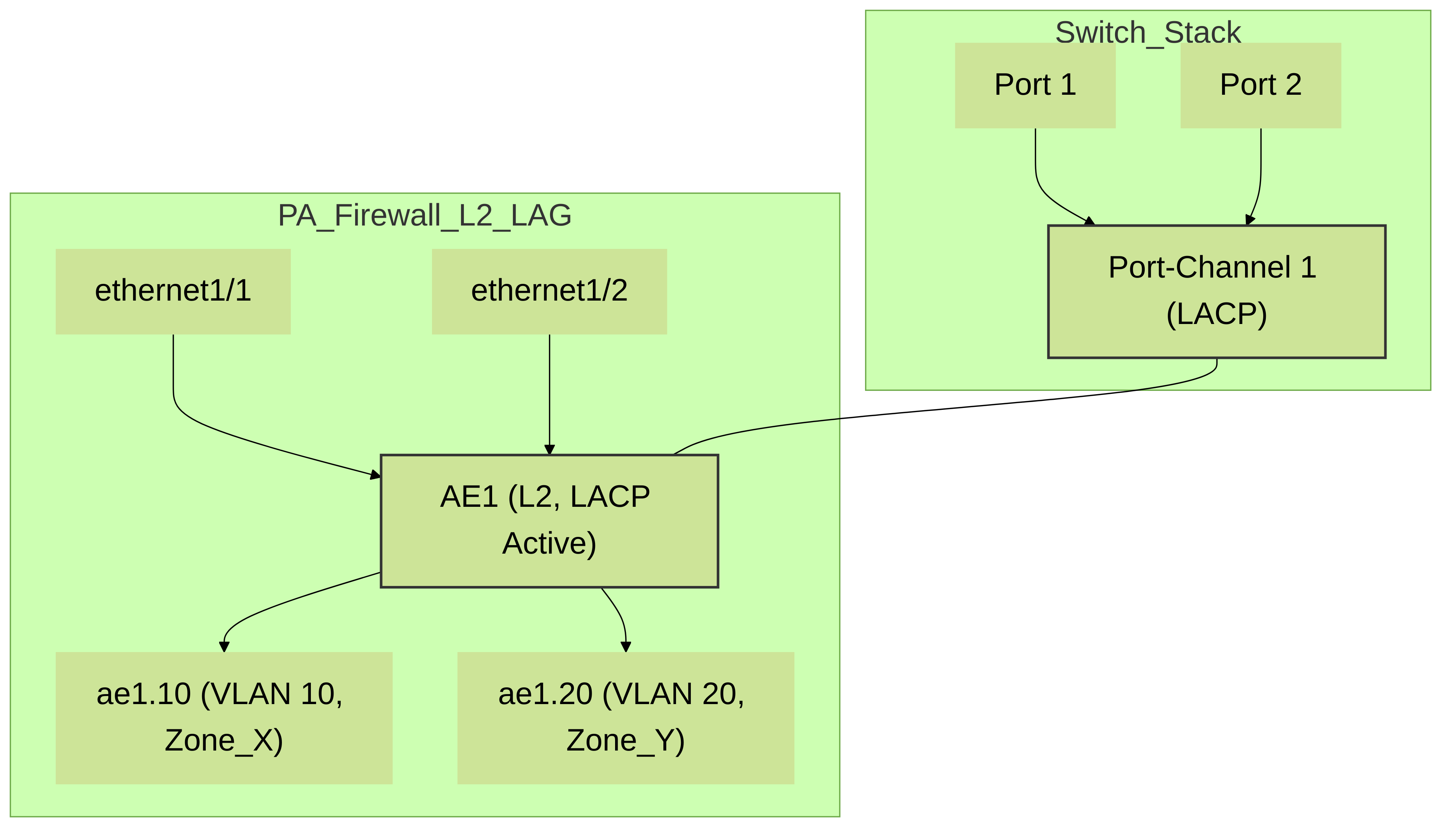
Palo Alto Networks firewall with
ethernet1/1
and
ethernet1/2
bundled into Aggregate Ethernet interface
ae1
using LACP. The
ae1
interface is configured in Layer 2 mode and has subinterfaces for VLAN 10 and VLAN 20, connecting to a switch stack with a corresponding Port-Channel.
🛡️ Feature Support on Layer 2 Interfaces: A Closer Look
SSL Decryption
Palo Alto Networks firewalls fully support SSL Forward Proxy decryption on Layer 2 interfaces. This allows the firewall to decrypt and inspect SSL/TLS encrypted traffic passing through its L2 segments, enabling visibility for App-ID, Threat Prevention, URL Filtering, and WildFire analysis on encrypted sessions. A Decryption Profile and Decryption Policy rules are configured similarly to L3 deployments. The firewall needs to be trusted by clients (its forward trust certificate installed in client browsers/systems).
Quality of Service (QoS)
QoS is supported on Layer 2 physical interfaces and Aggregate Ethernet (AE) interfaces configured in Layer 2 mode.
- Configuration: QoS is enabled on the main physical or AE interface ( Network > Interfaces > Ethernet/Aggregate Ethernet > select interface > Advanced > QoS - check "Enable QoS"). Then, a QoS Profile is assigned to that interface.
- QoS Policy Rules: QoS Policy rules ( Policies > QoS ) define traffic classes (based on application, source/destination zone, user, etc.) and assign them to QoS classes defined in the QoS Profile (e.g., real-time, critical, best-effort).
- Enforcement: QoS is enforced on egress traffic from the interface. For L2 subinterfaces, QoS settings on the parent physical/AE interface apply to all traffic egressing through its subinterfaces. Granular per-subinterface QoS is typically managed by overall policy and classification.
-
PCNSE/PCNSA Exam Note (Palo Alto Networks): Remember that QoS is enabled on the physical/AE interface and applies to egress traffic. QoS policies classify traffic, and QoS Profiles define bandwidth allocation for those classes.
App-ID™, User-ID™, Content-ID™
- App-ID: Fully functional on L2 interfaces. The firewall identifies applications regardless of port, protocol, encryption (with SSL decryption), or evasive tactics.
- User-ID: Can be integrated with L2 deployments. If user information is available (e.g., via User-ID Agent, AD integration, GlobalProtect), policies can be user-based. The security zone associated with the L2 interface must have "Enable User Identification" checked.
- Content-ID: Threat Prevention (Antivirus, Anti-Spyware, Vulnerability Protection), URL Filtering, File Blocking, and WildFire are all fully supported on traffic traversing L2 interfaces, provided appropriate security profiles are attached to security policy rules.
Zone Protection Profiles
Zone Protection Profiles can be applied to security zones that contain Layer 2 interfaces or subinterfaces. This helps protect the network segment behind the L2 interface from reconnaissance attacks (port scans, host sweeps) and various types of floods (SYN, UDP, ICMP, etc.).
NAT (Network Address Translation)
As stated before, NAT is a Layer 3 function and is not performed directly on Layer 2 interfaces because they lack IP addresses. To implement NAT for traffic originating from a Layer 2 segment:
- Traffic from the L2 segment must be directed towards a Layer 3 interface on the Palo Alto Networks firewall (e.g., a routed physical interface, a Layer 3 subinterface, or a VLAN interface/SVI).
- A NAT policy is then configured on the firewall that applies to traffic transiting from the zone of the L2 segment (source zone) to the zone of the L3 egress interface (destination zone), typically an "untrust" or "internet" zone.
_pass.png)
Traffic from a client on an L2 segment (
Zone_Internal
via
eth1/1
) passes through the firewall. To be NATted, it must be routed to an L3 interface (
eth1/2
in
Zone_External
) where a NAT policy is applied for internet access.
🛠️ Troubleshooting Layer 2 Deployments
Common issues and troubleshooting steps for L2 interfaces on Palo Alto Networks firewalls:
-
No Traffic Passing:
-
Physical Layer:
Check cabling, SFPs, link status lights on firewall and switch. Use `show interface
` CLI. -
Interface Configuration:
Verify interface is UP/UP. Ensure correct L2 type, VLAN tagging on subinterfaces matches switch trunk config.
show interface ethernet1/1.10
- Zone Assignment: Confirm L2 interface/subinterface is in a Security Zone. Traffic cannot pass if not in a zone.
- Security Policies: Ensure there are security policies allowing traffic between the source and destination zones. Check Traffic Logs.
-
MAC Learning:
Check MAC address table. `show mac interface
` or `show mac all | match `. If MACs aren't learned, suspect L2 connectivity or VLAN issues. - STP Issues: An STP loop in the adjacent network could be blocking traffic or causing instability. Check switch STP status.
-
Physical Layer:
Check cabling, SFPs, link status lights on firewall and switch. Use `show interface
-
Intermittent Connectivity:
-
Duplex/Speed Mismatch:
Ensure settings match between firewall and switch. Autonegotiation issues can cause this. `show interface
` for errors/drops. - MTU Mismatch: Verify consistent MTU across the path.
- Resource Exhaustion: Unlikely in typical L2, but check session table `show session info` if traffic volume is extreme.
-
Duplex/Speed Mismatch:
Ensure settings match between firewall and switch. Autonegotiation issues can cause this. `show interface
-
VLAN Specific Issues:
- Incorrect Tag: Subinterface tag on firewall must match VLAN ID used on switch.
- Allowed VLANs: Switch trunk port must allow the required VLANs.
- Native VLAN Mismatch: If using native VLANs, ensure configurations are consistent (though generally explicit tagging is clearer).
-
Useful CLI Commands:
-
show interface: Status, speed, duplex, MTU, errors. -
show mac all [interface: MAC address table.] [vlan ] -
show counter global | match: Global counters for drops, errors. -
show counter interface: Interface-specific counters. -
show session all filter source: Check if sessions are being created.destination -
show VPan-os-versioning logging traffic match source: To see live traffic logs. (Actual command `less mp-log traffic.log` or GUI logs are better for historical) -
debug dataplane packet-diag set filter ...(use with caution and Palo Alto Networks support guidance): For deep packet inspection flow. -
show arp all(less relevant for L2 interface itself, but for overall connectivity).
-
📚 Additional Resources (Official Palo Alto Networks)
- Layer 2 Interfaces - PAN-OS Networking Admin Guide
- Configure a Layer 2 Interface
- Configure a Layer 2 Interface, Subinterface, and VLAN
- Configure an Aggregate Interface Group
- Palo Alto Networks LIVEcommunity (for discussions and community expertise)