Palo Alto Networks Tunnel Interfaces: Mastering IPsec, GRE, and GlobalProtect for PCNSE
Palo Alto Networks Tunnel Interfaces: The Foundation of Secure Connectivity
In the Palo Alto Networks ecosystem, Tunnel interfaces are fundamental logical Layer 3 interfaces. Their primary role is to serve as the entry and exit point for traffic that needs to be routed through various types of Virtual Private Network (VPN) tunnels. These are not physical interfaces but rather software constructs within PAN-OS that enable secure and flexible network segmentation and connectivity. Understanding their configuration and behavior is critical for the PCNSE certification and effective firewall administration.
Tunnel interfaces are versatile and are used as the terminating points for:
- IPsec Tunnels: For site-to-site VPNs and secure remote access.
- GRE Tunnels: For encapsulating various network layer protocols, often used for simpler point-to-point links or in conjunction with IPsec.
- GlobalProtect: For secure remote access for endpoints, leveraging IPsec or SSL VPNs that terminate on a tunnel interface.
Core Characteristics and Configuration in PAN-OS
-
Naming Convention:
Tunnel interfaces in PAN-OS are uniquely identified using the format
tunnel.N, where 'N' is a numerical identifier ranging from 1 to 9999. For example,tunnel.1,tunnel.100. This number is locally significant to the firewall. - Layer 3 Operation: As Layer 3 interfaces, they require IP addressing (though optional in some specific scenarios) to participate in routing and for tunnel health monitoring.
- Virtual Router Assignment: Crucially, a tunnel interface must be assigned to a Virtual Router (VR) within PAN-OS (e.g., `default` VR). This allows the firewall to make routing decisions for traffic destined for or originating from the tunnel. Without assignment to a VR, the tunnel interface cannot route traffic.
- Security Zone Assignment: Equally important, a tunnel interface must be assigned to a Security Zone. This zone assignment is paramount because all Palo Alto Networks Security policies are zone-based. Traffic exiting the tunnel (decapsulated) or entering the tunnel (to be encapsulated) will be evaluated against Security policies based on its source and destination zones. The tunnel interface's zone determines one of these. If a tunnel interface is not in a zone, traffic through it will be dropped due to lack of policy match.
-
IP Addressing (IPv4/IPv6):
-
While technically optional for some basic IPsec policy-based VPNs where Proxy IDs define all traffic, assigning an IP address to a tunnel interface is a
Palo Alto Networks best practice
and practically required for:
- Route-based VPNs: Where routing decisions determine what traffic enters the tunnel.
- Dynamic Routing Protocols: To establish OSPF or BGP adjacencies over the tunnel. The tunnel interface IP acts as the source/neighbor IP.
- Tunnel Monitoring: PAN-OS Tunnel Monitoring often uses ICMP pings sourced from the tunnel interface IP to a destination across the tunnel.
- GRE Tunnels: Often require IP addressing for routing traffic through them and for keepalives.
- The IP address can be a private IP, and for point-to-point tunnels, a /30 or /31 subnet is common.
-
While technically optional for some basic IPsec policy-based VPNs where Proxy IDs define all traffic, assigning an IP address to a tunnel interface is a
Palo Alto Networks best practice
and practically required for:
- Management Profile (Optional): A Management Profile can be attached to a tunnel interface to allow services like ping, SNMP, or User-ID agent communication directly with the tunnel interface IP. This is useful for troubleshooting and monitoring.
- MTU: The MTU for a tunnel interface can be configured. PAN-OS automatically accounts for IPsec/GRE overhead when processing traffic through the tunnel, potentially adjusting TCP MSS.
Configuration is done in PAN-OS via Network > Interfaces > Tunnel .
Conceptual overview of a Palo Alto Networks Tunnel Interface and its key associations within PAN-OS.
Deep Dive: Tunnel Interfaces in Palo Alto Networks IPsec VPNs
Tunnel interfaces are the cornerstone of route-based IPsec VPNs on Palo Alto Networks firewalls. They provide a logical point to which traffic is routed before being encrypted and sent to the VPN peer.
Key Palo Alto Networks Components for IPsec VPNs
-
IKE Gateway (Phase 1):
- Configured under Network > Network Profiles > IKE Crypto (for crypto profiles) and Network > IKE Gateways .
- Defines parameters for IKE Phase 1 negotiation: authentication method (Pre-Shared Key or Certificate), Diffie-Hellman group, encryption, hashing algorithms, and Dead Peer Detection (DPD) or tunnel monitoring.
- Specifies local and peer identification (IP address, FQDN, User FQDN).
-
IPsec Crypto Profile (Phase 2 Proposal):
- Configured under Network > Network Profiles > IPsec Crypto .
- Defines encryption and authentication algorithms (e.g., AES-256, SHA256), and the Encapsulating Security Payload (ESP) protocol for IKE Phase 2. Perfect Forward Secrecy (PFS) using DH groups can also be enabled here.
-
Tunnel Interface (Logical Interface):
- As described above, assigned to a Virtual Router and Security Zone.
- Can have an IP address (highly recommended for route-based VPNs).
-
IPsec Tunnel Configuration (Phase 2 Policy):
- Configured under Network > IPsec Tunnels .
-
This is where everything ties together:
- It references the IKE Gateway configured in step 1.
- It references the Tunnel Interface created in step 3.
- It selects an IPsec Crypto Profile for Phase 2 parameters.
-
Proxy IDs (Critical for "Interesting Traffic"):
-
In a route-based VPN, typically set to Local:
0.0.0.0/0, Remote:0.0.0.0/0, Protocol: Any. This allows routing decisions to control what traffic enters the tunnel. -
When connecting to a
policy-based VPN peer
(a device that uses specific network definitions, not routes, to define VPN traffic), you MUST configure Proxy IDs to match the peer's encryption domain. For example, Local:
192.168.1.0/24, Remote:10.10.0.0/16. Mismatched Proxy IDs are a common cause of IKE Phase 2 failures. - Multiple Proxy IDs can be configured if needed to match a peer with multiple specific encryption domains.
-
In a route-based VPN, typically set to Local:
- Tunnel Monitor (Optional but Recommended): Allows the firewall to send probes (typically pings) to an IP address on the remote side of the tunnel. If replies are not received, the firewall can mark the tunnel as down and potentially reroute traffic or trigger alerts. The source IP for the monitor is often the local Tunnel Interface IP.
0.0.0.0/0
) and interoperating with policy-based VPN peers (Proxy IDs must match specific subnets). Understand that the Tunnel Interface is the logical entry/exit point for traffic *before* encryption and *after* decryption.
IPsec Traffic Flow with Tunnel Interfaces
- An outbound packet arrives at the firewall.
-
A route lookup in the Virtual Router determines the egress interface is a
tunnel.Ninterface. -
The packet is notionally passed to the
tunnel.Ninterface. -
Security Policy lookup occurs: Source Zone (e.g., 'Trust') to Destination Zone (the zone of
tunnel.N, e.g., 'VPN-Zone'). -
If allowed by policy, the firewall identifies that
tunnel.Nis bound to an IPsec Tunnel configuration. -
The firewall checks if an IKE Phase 2 Security Association (SA) matching the packet's source/destination (as per Proxy ID) exists.
- If no SA, and IKE Phase 1 SA is up, it initiates IKE Phase 2 negotiation.
- If IKE Phase 1 is down, it initiates IKE Phase 1 negotiation.
- Once the IPsec SA is established, the original packet is encrypted and encapsulated according to the IPsec Crypto Profile (ESP).
- The new, encrypted packet (with an outer IP header matching the IKE Gateway local/peer IPs) is routed out the physical interface defined in the IKE Gateway.
For inbound encrypted traffic, the process is reversed: decapsulation, decryption, then the original inner packet is passed to the tunnel interface, a new session is created for the inner packet, and it's processed by Security Policy (Source Zone: 'VPN-Zone', Destination Zone based on routing of the inner packet).
> show vpn ike-sa gateway <ike-gateway-name>  // Verifies IKE Phase 1 status
> show vpn ipsec-sa tunnel <ipsec-tunnel-name> // Verifies IKE Phase 2 status and Proxy IDs
> test vpn ike-sa gateway <ike-gateway-name>   // Tests IKE Phase 1 negotiation
> test vpn ipsec-sa tunnel <ipsec-tunnel-name> // Tests IKE Phase 2 negotiation
Simplified IPsec outbound traffic processing flow in PAN-OS involving a Tunnel Interface.
Deep Dive: Tunnel Interfaces in Palo Alto Networks GlobalProtect
GlobalProtect, Palo Alto Networks' comprehensive remote access solution, heavily relies on tunnel interfaces to secure connections from endpoints (laptops, mobile devices) to the corporate network.
- Tunnel Mode Operation: When GlobalProtect clients connect in "tunnel mode" (the most common deployment), PAN-OS establishes a VPN tunnel (either IPsec or SSL-VPN) between the GlobalProtect client and a GlobalProtect Gateway on the firewall. This Gateway configuration explicitly references a tunnel interface on the firewall, which acts as the server-side endpoint for these client VPNs.
-
Protocols - IPsec and SSL:
- GlobalProtect primarily attempts to establish an IPsec tunnel for better performance. It typically uses UDP 4501 (NAT-Traversal) for this.
- If IPsec establishment fails (e.g., due to restrictive networks blocking UDP 4501), the GlobalProtect client can automatically fall back to SSL-VPN (TLS) , usually over TCP 443.
- Regardless of the underlying protocol (IPsec or SSL), the traffic is logically terminated on the assigned tunnel interface on the firewall.
- IP Pool Assignment: The GlobalProtect Gateway configuration includes an IP pool from which connecting clients are assigned an IP address. This IP address appears as the source IP for traffic originating from the client when it traverses the firewall. The tunnel interface itself does not need an IP from this pool; it typically has its own static IP for routing and management.
-
Split Tunneling:
- GlobalProtect offers granular split tunneling capabilities, configured in the Gateway's Client Settings. This determines which traffic from the endpoint goes through the VPN tunnel and which goes directly to the internet or local network.
- Access Routes: Define destination subnets that will be sent through the tunnel. If no access routes are defined (0.0.0.0/0), all traffic goes through the tunnel (full tunnel).
- Exclude Routes: Define specific destination subnets to bypass the tunnel.
- Domain/Application-Based Split Tunneling: Allows specific domains or applications (identified by App-ID) to be included or excluded from the tunnel, offering more precise control than just IP subnets.
- Traffic destined for the tunnel is routed to the GlobalProtect client's virtual adapter, encapsulated, and sent to the firewall's GlobalProtect Gateway, terminating on its associated tunnel interface.
-
Security Policy for GlobalProtect Users:
- Once traffic from a GlobalProtect client is decrypted/decapsulated and hits the tunnel interface, it is subject to Security Policy.
- The source zone for this traffic will be the zone to which the GlobalProtect tunnel interface is assigned.
- User-ID integration with GlobalProtect allows policies to be written based on the authenticated user/group, providing granular access control.
GlobalProtect Gateway configuration is at Network > GlobalProtect > Gateways .
Simplified traffic flow for GlobalProtect in tunnel mode, highlighting the role of the tunnel interface on the Palo Alto Networks firewall and split tunneling.
Deep Dive: Palo Alto Networks GRE Tunnels
Generic Routing Encapsulation (GRE), defined by RFC 2784, is a tunneling protocol developed by Cisco Systems that can encapsulate a wide variety of network layer protocol packet types inside virtual point-to-point links over an Internet Protocol network. Palo Alto Networks firewalls can terminate GRE tunnels, enabling specific routing paths for traffic.
While simpler than IPsec (as it lacks inherent encryption), GRE is useful for:
- Sending traffic that IPsec cannot easily handle (e.g., some multicast or non-IP protocols, though PAN-OS primarily focuses on IP).
- Establishing connectivity where encryption is handled by other means or is not required.
- Running dynamic routing protocols over the tunnel, as they often integrate smoothly with GRE.
- Directing traffic to cloud-based security services or specific partner networks that require GRE.
 (Image shows a Palo Alto Networks firewall connecting via a GRE tunnel over the internet to a cloud service, with an internal client's traffic being routed through this tunnel.)
GRE Traffic Handling and Policy in PAN-OS
Understanding how PAN-OS processes GRE traffic is key:
When the firewall encapsulates traffic into a GRE tunnel (outbound from firewall's perspective):
-
A packet arrives, and a route lookup determines its egress interface is a GRE-associated
tunnel.Ninterface. - Security policy is checked for the original packet (e.g., from zone `Trust` to zone `GRE-Zone` where `tunnel.N` resides).
- If allowed, PAN-OS adds the GRE header and the new outer IP header (source IP is the GRE tunnel's local endpoint, destination is the peer endpoint).
- Importantly, PAN-OS does not create a new session or perform a new Security policy lookup for the act of GRE encapsulation itself. The policy decision was already made on the original packet.
- The encapsulated GRE packet is then routed out the physical interface towards the GRE peer.
When the firewall decapsulates GRE traffic (inbound to firewall's perspective):
- An incoming packet with IP Protocol 47 (GRE) arrives on a physical interface.
- A session is created for this outer GRE packet.
-
Security Policy (Outer Header):
A Security policy lookup is performed for this GRE packet itself.
- The source zone is the zone of the ingress physical interface (e.g., `Untrust`).
-
The destination zone is the zone of the
tunnel.Ninterface that is configured to terminate this GRE traffic (e.g., `GRE-Zone`). - An explicit Security policy rule must allow this traffic (application `gre` or service for IP protocol 47) from the ingress zone to the GRE tunnel's zone.
- If the ingress physical interface and the GRE tunnel interface are in the same zone, default intrazone-allow rules might permit it, but an explicit intrazone-deny could block it. Best practice is often to have them in different zones for clarity.
- If the outer GRE packet is allowed, PAN-OS decapsulates it, removing the outer IP and GRE headers.
-
Security Policy (Inner Packet):
The original inner packet is now processed:
- A new session is typically created for this inner packet.
- A route lookup is performed for the inner packet's destination IP.
-
A Security policy lookup is performed for this inner packet based on its source zone (the zone of the GRE
tunnel.Ninterface) and its new destination zone (determined by the routing lookup for the inner packet).
MTU and MSS Considerations for GRE
GRE encapsulation adds overhead to packets:
- GRE Header: Typically 4 bytes (basic GRE without options like keys or sequence numbers).
- New IP Header: Typically 20 bytes (for IPv4).
- Total Overhead: Around 24 bytes.
This overhead reduces the effective MTU for the payload. If the physical interface MTU is 1500 bytes, the GRE tunnel's effective payload MTU becomes 1500 - 24 = 1476 bytes. PAN-OS automatically attempts to manage this for TCP traffic by adjusting the Maximum Segment Size (MSS) advertised during TCP handshakes traversing the tunnel.
- TCP MSS Clamping: PAN-OS by default reduces the MSS for TCP sessions going over tunnels. The default reduction often accounts for TCP/IP headers (40 bytes) plus typical tunnel overhead. For GRE, it would consider the ~24 bytes GRE/IP overhead.
- This can be manually configured under Network > Network Profiles > TCP MSS by creating a profile and applying it to the tunnel interface or to security policies. The firewall can be set to clear the "Don't Fragment" (DF) bit or to clamp MSS to a specific value.
Palo Alto Networks GRE Limitations
- No Inherent Encryption: As stated, standard GRE offers no encryption. Use GRE over IPsec for confidentiality.
- Routing Loops: Routing GRE tunnel traffic back out another GRE tunnel or an IPsec tunnel terminating on the *same* firewall is complex and generally not supported through simple static routing. Policy Based Forwarding (PBF) or specific SD-WAN scenarios might offer solutions for more complex routing needs, but standard routing will likely lead to recursion issues. However, traffic *arriving* from a GRE tunnel can be routed out an IPsec tunnel.
- QoS: QoS policies are applied to the traffic *before* it enters the GRE tunnel or *after* it exits. QoS is not directly applied to the GRE tunnel construct itself in the same way it might be on a physical interface, though the ToS byte can be copied.
-
NAT:
- NAT is not supported for the GRE tunnel endpoints themselves (the outer IP headers of the GRE packet).
- NAT can be applied to the *inner* traffic (the original packets) before encapsulation or after decapsulation, using standard NAT policies on the firewall.
- Decryption Broker: A physical interface cannot be a GRE tunnel endpoint if it's also configured as a decryption broker interface for SSL Forward Proxy.
- Tunnel Content Inspection for GRE: If you only need to inspect GRE traffic passing *through* the firewall (i.e., the firewall is not a GRE endpoint but is in the path), you should configure Tunnel Content Inspection ( Objects > Tunnel Inspection ). This is different from terminating a GRE tunnel.
Palo Alto Networks firewall processing flow for an incoming GRE packet, highlighting the dual policy checks.
Configuration: Creating a Standard GRE Tunnel in PAN-OS
This section details the steps to configure a basic GRE tunnel between a Palo Alto Networks firewall and a peer device.
-
Step 1: Create a Tunnel Interface
- Navigate to Network > Interfaces > Tunnel .
- Click Add at the bottom.
-
Interface Name:
Enter a unique tunnel number (e.g.,
tunnel.2). -
Config Tab:
- Virtual Router: Select the Virtual Router this tunnel interface will belong to (e.g., `default`). This is mandatory for routing.
- Security Zone: Click Add and select an existing zone or create a new zone (e.g., `GRE_Zone` or `VPN_Zone`). This zone will be used for Security policies governing traffic to/from this tunnel. This is mandatory.
- (Multi-VSYS) Virtual System: Assign to the correct VSYS if applicable.
-
IPv4 Tab (or IPv6):
-
(Optional but Highly Recommended) Click
Add
and assign an IP address and netmask to this tunnel interface. This IP is used for routing protocols over GRE, tunnel monitoring/keepalives, and as a next-hop target. Example:
192.168.100.1/30. The peer device's GRE tunnel interface should have an IP in the same subnet (e.g.,192.168.100.2/30).
 (Image shows PAN-OS GUI for configuring a tunnel interface: assigning tunnel.2 to virtual router 'default', security zone 'VPN_Zone', and IP address 192.168.100.1/30.)
-
(Optional but Highly Recommended) Click
Add
and assign an IP address and netmask to this tunnel interface. This IP is used for routing protocols over GRE, tunnel monitoring/keepalives, and as a next-hop target. Example:
- Click OK .
-
Step 2: Configure the GRE Tunnel Parameters
- Navigate to Network > GRE Tunnels .
- Click Add .
- Name: Enter a descriptive name for this GRE tunnel configuration (e.g., `GRE_to_Cloud_Service`).
-
Interface:
Select the
physical or loopback interface
on the firewall that will be the source of the outer GRE IP packets (e.g., your external-facing interface like
ethernet1/1, or a loopback interface). -
Local Address:
-
Type:
Select
IP. -
Address:
Choose the IP address of the interface selected above (e.g., the public IP of
ethernet1/1). This is the source IP of the outer GRE packet.
-
Type:
Select
- Peer Address: Enter the public/reachable IP address of the remote GRE endpoint (the device at the other end of the tunnel). This is the destination IP of the outer GRE packet.
-
Tunnel Interface:
Select the logical tunnel interface created in Step 1 (e.g.,
tunnel.2). This links the GRE encapsulation parameters to the logical routing interface. - TTL (Time To Live): Default is 64. Adjust if necessary, though default is usually fine.
- Copy ToS Header (Optional): Check this if you want the ToS (Type of Service) byte from the inner packet's IP header to be copied to the outer GRE IP header. This can help preserve QoS markings across the GRE tunnel if intermediate devices honor ToS.
 (Image shows PAN-OS GUI for GRE Tunnel configuration: Name 'GRE-to-Branch', Interface 'ethernet1/1', Local IP '1.1.1.1', Peer IP '2.2.2.2', Tunnel Interface 'tunnel.2'.)
-
Step 3: (Best Practice) Enable Keep Alive for GRE
- In the same GRE Tunnel configuration window (from Step 2), check the Enable Keep Alive box.
- GRE Keepalives are proprietary to Palo Alto Networks and may not interoperate with all third-party devices. They work by sending GRE packets (using the same source/destination IPs as the data packets) and expecting responses.
- Interval: How often to send keepalive probes (default: 10 seconds).
- Retry: Number of consecutive missed keepalives before declaring the tunnel down (default: 3).
- Hold Timer: This is a Palo Alto Networks specific timer. When a GRE tunnel that was down comes back up (keepalives succeed), the firewall waits for this hold timer duration (default: 5 * Interval = 50 seconds) before considering the tunnel fully operational and potentially re-installing routes through it. This helps prevent route flapping if the tunnel is unstable. If set to 0, the tunnel is used immediately upon keepalives succeeding.
-
When keepalives fail beyond the retry count, PAN-OS will bring the associated logical
tunnel.Ninterface administratively down. This allows routing protocols or static route monitoring to detect the failure and reroute traffic.
- Click OK to save the GRE Tunnel configuration.
-
Step 4: Configure Routing
- To direct traffic through the newly created GRE tunnel, you need to configure routing.
-
Static Route:
Navigate to
Network > Virtual Routers > (select your VR) > Static Routes
.
- Add a route for the destination network(s) on the other side of the GRE tunnel.
-
Set the
Interface
to your GRE tunnel interface (e.g.,
tunnel.2). -
Set the
Next Hop
typically to the IP address assigned to the
peer's GRE tunnel interface
(e.g.,
192.168.100.2if your localtunnel.2is192.168.100.1). If the tunnel interface is unnumbered, you might select 'None' for next hop type if supported by the specific PAN-OS version and scenario (less common for GRE).
-
Dynamic Routing (OSPF/BGP):
-
If using OSPF, enable OSPF on the GRE
tunnel.Ninterface and ensure it's in the correct OSPF area. Adjacencies will form over the tunnel IPs. - If using BGP, configure BGP neighbors using the GRE tunnel interface IPs.
-
If using OSPF, enable OSPF on the GRE
-
Step 5: Configure Security Policies
-
As discussed in "GRE Traffic Handling", ensure you have Security policies:
- To allow the incoming GRE protocol (IP protocol 47 or application `gre`) from the zone of your physical ingress interface to the zone of your GRE tunnel interface.
- To allow the decapsulated (inner) traffic from the zone of your GRE tunnel interface to its destination zone within your network.
- To allow outbound traffic from its source zone to the zone of your GRE tunnel interface.
-
As discussed in "GRE Traffic Handling", ensure you have Security policies:
-
Step 6: Commit Changes
- Click Commit in the PAN-OS GUI to apply the configuration.
-
Step 7: Configure the Peer Device
- Ensure the remote GRE endpoint is configured with compatible settings (peer/local IPs reversed, same tunnel interface IP subnet if used, etc.).
-
Step 8: Verify Connectivity and Status
-
CLI Commands:
> show interface tunnel.N // Check if tunnel interface is up/up and keepalive status > ping source <local_tunnel_interface_IP> host <peer_tunnel_interface_IP> // Test reachability over tunnel > show routing route type static // Verify static routes > show routing fib-lookup virtual-router <vr_name> ip <destination_ip_across_tunnel> // Test routing path > show counter interface tunnel.N // Check packet counters > show session all filter tunnel <tunnel.N> // View active sessions through tunnel - If keepalives are enabled and working, the `show interface tunnel.N` command will indicate the tunnel state as "Up". If keepalives fail, it will show as "Down".
-
CLI Commands:
Advanced Configuration: GRE over IPsec Tunnel Using Loopback Interfaces
This scenario is common when you need the robust security of IPsec combined with the flexibility of GRE (e.g., for running dynamic routing protocols that don't work well directly over IPsec, or for transporting multicast traffic). Using loopback interfaces as the GRE tunnel endpoints provides stable IP addresses that are not tied to physical interface IPs, which might change. The IPsec tunnel encrypts the GRE traffic.
Essentially, you create two tunnels:
- An IPsec tunnel between the firewalls' physical/external IPs (or other loopbacks dedicated for IPsec).
- A GRE tunnel whose source and destination IPs are loopback interfaces on each firewall. The traffic for this GRE tunnel (i.e., packets sourced from one loopback to the other) is then routed *through* the established IPsec tunnel.
Example Topology:
-
Firewall-A (FW-A):
-
Public IP:
1.1.1.1(onethernet1/1) -
IPsec Tunnel Interface:
tunnel.1(IP:192.168.1.1/30) -
Loopback for GRE:
loopback.1(IP:10.20.20.1/32) -
GRE Tunnel Interface:
tunnel.2(IP:172.16.2.1/30, optional, for routing over GRE)
-
Public IP:
-
Firewall-B (FW-B):
-
Public IP:
2.2.2.2(onethernet1/1) -
IPsec Tunnel Interface:
tunnel.1(IP:192.168.1.2/30) -
Loopback for GRE:
loopback.1(IP:10.30.30.1/32) -
GRE Tunnel Interface:
tunnel.2(IP:172.16.2.2/30, optional, for routing over GRE)
-
Public IP:
GRE over IPsec using Loopback Interfaces. User traffic is GRE encapsulated (using loopback IPs as GRE endpoints), and then this GRE packet is IPsec encapsulated (using physical IPs as IPsec endpoints).
Procedure (Palo Alto Networks Focus):-
Configure Base IPsec Tunnel (e.g.,
tunnel.1):-
Set up a standard route-based IPsec tunnel between FW-A (
1.1.1.1) and FW-B (2.2.2.2). -
Assign
tunnel.1on FW-A IP192.168.1.1/30and on FW-B IP192.168.1.2/30. -
Ensure this IPsec tunnel (IKE Phase 1 & Phase 2) is UP. Proxy IDs for this IPsec tunnel should typically be
0.0.0.0/0(Local and Remote) if its purpose is to carry various routed traffic, including the GRE packets. -
Zone: Assign
tunnel.1to a suitable zone (e.g., `IPSEC_Transit_Zone`).
CRITICAL (Palo Alto Networks): For this method, you do NOT check "Add GRE Encapsulation" within this base IPsec Tunnel configuration (Network > IPsec Tunnels > tunnel.1 config). That option is for when the *same* tunnel interface (e.g.,tunnel.1) handles both IPsec and GRE termination, and the GRE endpoints are the IPsec tunnel physical IPs. Here, we are building a GRE tunnel *on top of* an IPsec tunnel using different logical interfaces. -
Set up a standard route-based IPsec tunnel between FW-A (
-
Configure Loopback Interfaces (e.g.,
loopback.1):-
On FW-A: Create
loopback.1, assign IP10.20.20.1/32. Assign to Virtual Router (e.g., `default`) and a Security Zone (e.g., `LOOPBACK_Zone` or `TRUST_Zone` - consider the security implications of this zone). -
On FW-B: Create
loopback.1, assign IP10.30.30.1/32. Assign to VR and Zone similarly.
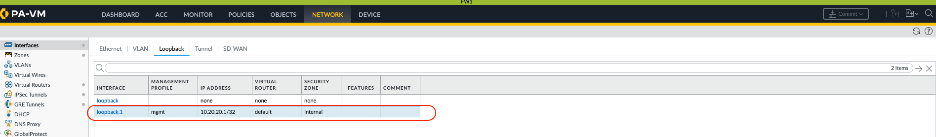 (Image shows PAN-OS GUI for configuring loopback.1 on FW-A with IP 10.20.20.1/32, assigned to virtual router 'default' and security zone 'Trust'.)
-
On FW-A: Create
-
Route Loopbacks Over the IPsec Tunnel:
- This is crucial: the firewalls must know how to reach each other's loopback IPs via the IPsec tunnel.
-
On FW-A: Add a static route: Destination
10.30.30.1/32(FW-B's loopback), Interfacetunnel.1(IPsec tunnel IF), Next Hop192.168.1.2(FW-B'stunnel.1IP). -
On FW-B: Add a static route: Destination
10.20.20.1/32(FW-A's loopback), Interfacetunnel.1(IPsec tunnel IF), Next Hop192.168.1.1(FW-A'stunnel.1IP). -
Verify: Ping from FW-A's loopback (
ping source 10.20.20.1 host 10.30.30.1) to FW-B's loopback. This traffic should be encrypted by the IPsec tunnel.
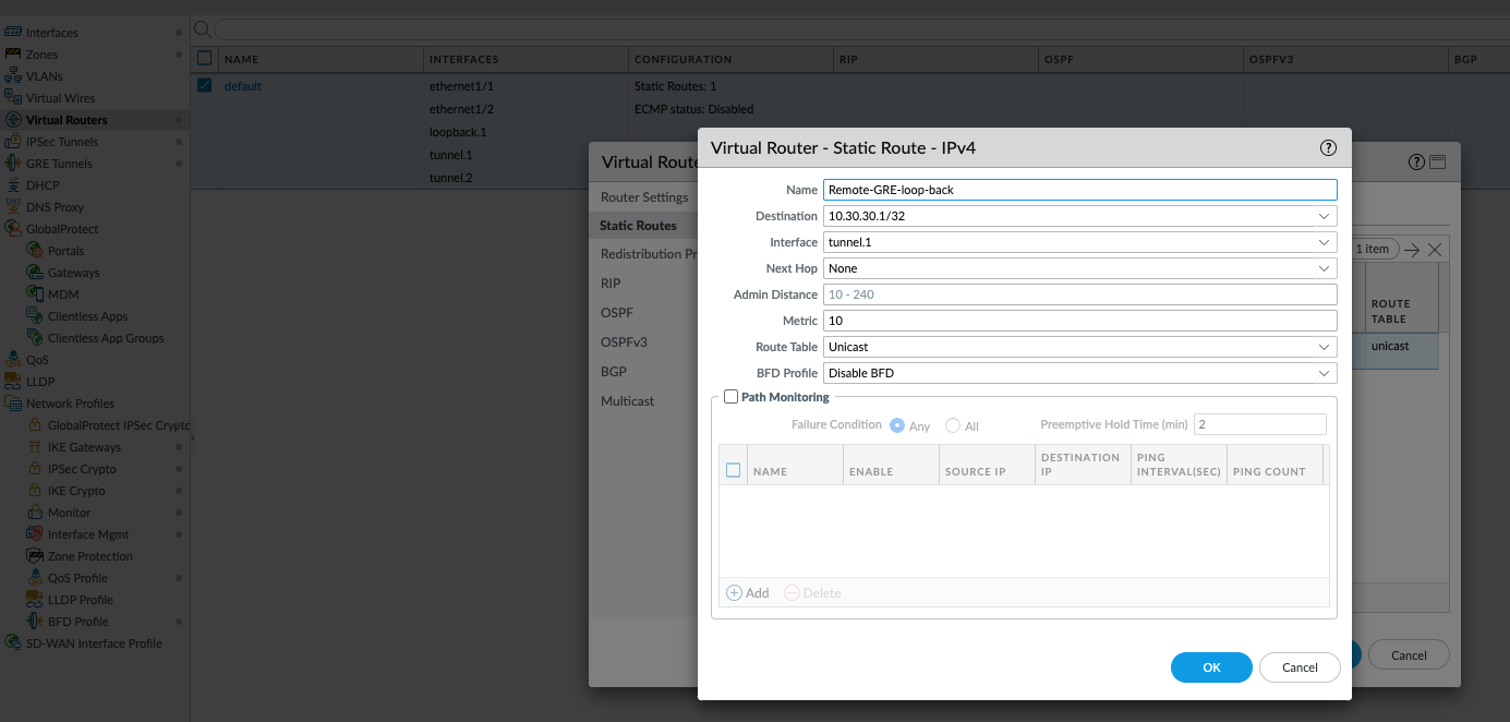 (Image shows static route on FW-A: Dest 10.30.30.1/32, Interface tunnel.1, Next Hop 192.168.1.2.)
-
Create GRE Tunnel Interface (e.g.,
tunnel.2):-
On FW-A: Create
tunnel.2. Assign to VR and a new Security Zone (e.g., `GRE_OVER_IPSEC_Zone`). Optionally assign an IP (e.g.,172.16.2.1/30). This IP is for traffic *inside* the GRE tunnel. -
On FW-B: Create
tunnel.2similarly (e.g., IP172.16.2.2/30), same VR and Zone.
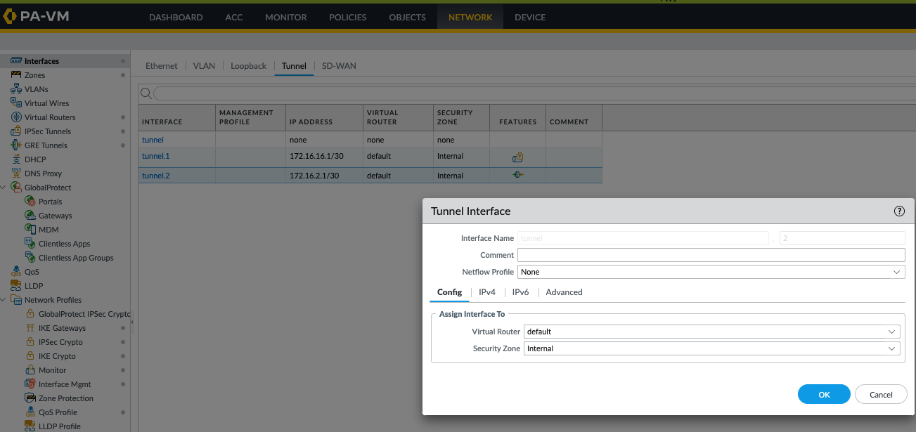 (Image shows PAN-OS GUI for tunnel.2 on FW-A: IP 172.16.2.1/30, VR 'default', Zone 'GRE_Zone'.)
-
On FW-A: Create
-
Configure GRE Tunnel Parameters Using Loopbacks:
- Navigate to Network > GRE Tunnels and Add a new GRE tunnel configuration.
-
On FW-A:
-
Interface:
Select
loopback.1(FW-A's loopback). This is the source interface for the GRE packet's outer header. -
Local Address:
IP
10.20.20.1(FW-A's loopback IP). -
Peer Address:
IP
10.30.30.1(FW-B's loopback IP). -
Tunnel Interface:
Select
tunnel.2(the logical GRE interface created in step 4). -
Enable
Keep Alive
(recommended). Note: GRE keepalives are sent between
10.20.20.1and10.30.30.1and will also be encrypted by the underlying IPsec tunnel.
-
Interface:
Select
-
Configure symmetrically on FW-B (Local Address
10.30.30.1, Peer Address10.20.20.1, sourcing from itsloopback.1, using itstunnel.2).
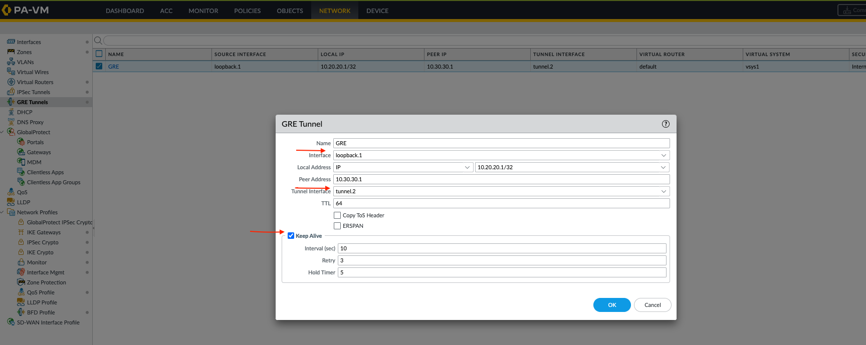 (Image shows GRE tunnel config on FW-A: Name 'GRE_via_IPsec', Interface 'loopback.1', Local IP '10.20.20.1', Peer IP '10.30.30.1', Tunnel Interface 'tunnel.2'.)
-
Confirm GRE Tunnel Status (
tunnel.2):-
Commit changes. The
tunnel.2interface state should eventually go UP if keepalives are successful. -
CLI:
admin@FW-A> show interface tunnel.2
--------------------------------------------------------------------------------
Name: tunnel.2, ID: 258
Operation mode: layer3
Virtual router: default
Interface MTU: 1476 (typically 1500 minus GRE/IP overhead; IPsec overhead is handled by tunnel.1)
Interface IP address: 172.16.2.1/30
...
--------------------------------------------------------------------------------
GRE tunnel name:             GRE_via_IPsec
tunnel interface state:      Up
disabled:                    False
...
keep alive enabled:          True
local-ip:                    10.20.20.1  (FW-A loopback.1)
peer-ip:                     10.30.30.1  (FW-B loopback.1)
local-phy-interface:         loopback.1
-
Commit changes. The
-
Route User Traffic Over the GRE Tunnel (
tunnel.2):-
Now, direct the actual user traffic (e.g., from LAN A to LAN B) through the GRE tunnel interface
tunnel.2. -
On FW-A: Static route for LAN B's network, Interface
tunnel.2, Next Hop172.16.2.2(FW-B'stunnel.2IP). -
On FW-B: Static route for LAN A's network, Interface
tunnel.2, Next Hop172.16.2.1(FW-A'stunnel.2IP). -
Alternatively, run a dynamic routing protocol (OSPF, BGP) over the
172.16.2.0/30network usingtunnel.2on both firewalls.
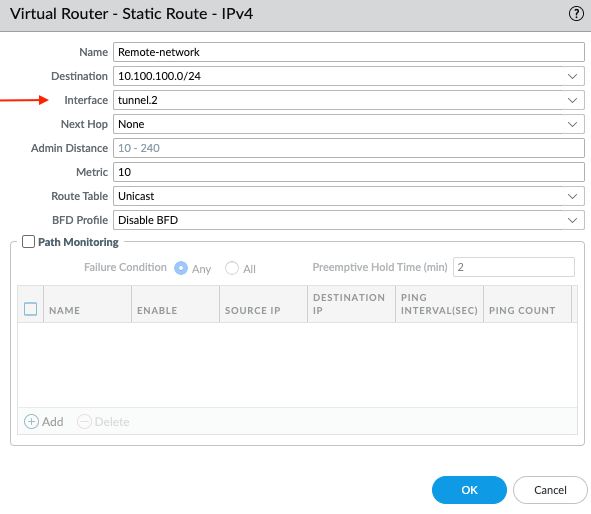 (Image shows static route on FW-A: Dest 10.100.100.0/24, Interface tunnel.2, Next Hop 172.16.2.2.)
-
Now, direct the actual user traffic (e.g., from LAN A to LAN B) through the GRE tunnel interface
-
Security Policies:
-
For IPsec Tunnel (
tunnel.1): Policies allowing traffic between the zone oftunnel.1and zones where loopbacks reside (if different), specifically for the GRE protocol (or IP protocol 47) if policy inspection is very granular here. Often, if loopbacks are in trusted zones andtunnel.1is also in a trusted-type zone, intrazone traffic might be allowed by default for the GRE packets sourced from/to loopbacks. However, explicit rules are clearer: Source Zone (ofloopback.1), Destination Zone (oftunnel.1), Application `gre`, Allow. And vice-versa for return GRE traffic. -
For GRE Tunnel (
tunnel.2): Policies allowing the actual user data between its original source zone and the zone oftunnel.2, and from the zone oftunnel.2to its final destination zone.
-
For IPsec Tunnel (
-
Verify End-to-End Traffic Flow:
- Ping from a host in LAN A to a host in LAN B.
-
Use
show session all filter destination <LAN_B_Host_IP>on FW-A. You should see:-
Initial session: Ingress
lan_interface, Egresstunnel.2(GRE tunnel). -
A second, related session (less obvious without deep packet inspection or specific logs for tunnel encapsulation): The GRE packet (source
10.20.20.1, destination10.30.30.1) then being egressed viatunnel.1(IPsec tunnel).
-
Initial session: Ingress
admin@FW-A> show session id <session_id_for_LAN_A_to_LAN_B_ping>
Session 7632 c2s flow: source: 10.10.10.1 [LAN_Zone] // Host in LAN A dst: 10.100.100.1 // Host in LAN B proto: 1 (ICMP) ... egress interface tunnel.2 // Traffic egresses into GRE tunnel ... s2c flow: ... ingress interface tunnel.2 // Return traffic from GRE tunnel ... -
On FW-A, if you check sessions for traffic between loopback IPs:
show session all filter source 10.20.20.1 destination 10.30.30.1, you would see these GRE packets (encapsulating the original user data) being egressed viatunnel.1(the IPsec tunnel).
tunnel.1
(for IPsec) and/or
tunnel.2
(for GRE payload), or more aggressive MSS clamping. The effective MTU for user data on
tunnel.2
will be physical MTU - IPsec overhead - GRE overhead.
Additional Palo Alto Networks Tunnel Concept Diagrams
_and_inbound_(bott_May_19_2025_04-29PM.png)
Conceptual traffic flow for outbound (top) and inbound (bottom) traffic involving Palo Alto Networks tunnel interfaces. Note the distinct policy checks before encapsulation and after decapsulation. The actual implementation involves many more detailed steps within PAN-OS datapath.
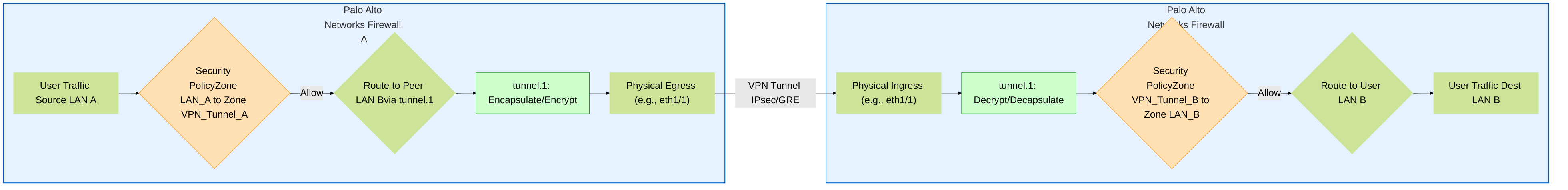
High-level representation of traffic flow through a site-to-site VPN tunnel between two Palo Alto Networks firewalls. It highlights the role of tunnel interfaces (
tunnel.1
implied), routing, and security policy enforcement at both ends.