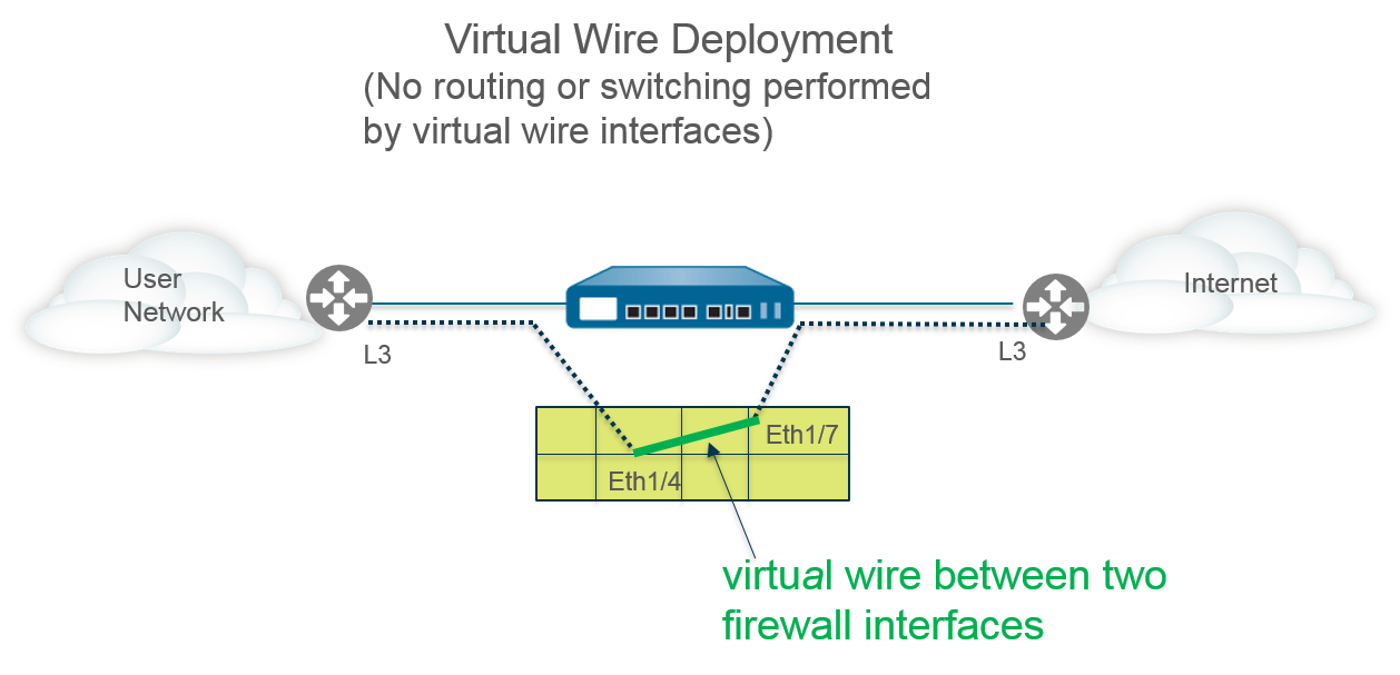
In a virtual wire deployment, you install a firewall transparently on a network segment by binding two firewall ports (interfaces) together . The virtual wire logically connects the two interfaces; hence, the virtual wire is internal to the firewall.
Use a virtual wire deployment only when you want to seamlessly integrate a firewall into a topology and the two connected interfaces on the firewall don't need to do any switching or routing . For these two interfaces, the firewall is considered a "bump in the wire" .
A virtual wire deployment simplifies firewall installation and configuration because you can insert the firewall into an existing topology without assigning MAC or IP addresses to the interfaces, redesigning the network, or reconfiguring surrounding network devices . The virtual wire supports blocking or allowing traffic based on virtual LAN (VLAN) tags, in addition to supporting security policy rules, App-ID, Content-ID, User-ID, decryption, LLDP, active/passive and active/active HA, QoS, zone protection (with some exceptions), non-IP protocol protection, DoS protection, packet buffer protection, tunnel content inspection, and NAT .
Each virtual wire interface is directly connected to a Layer 2 or Layer 3 networking device or host. The virtual wire interfaces have no Layer 2 or Layer 3 addresses . When one of the virtual wire interfaces receives a frame or packet, it ignores any Layer 2 or Layer 3 addresses for switching or routing purposes , but applies your security or NAT policy rules before passing an allowed frame or packet over the virtual wire to the second interface and on to the network device connected to it.
You wouldn't use a virtual wire deployment for interfaces that need to support switching, VPN tunnels, or routing because they require a Layer 2 or Layer 3 address. A virtual wire interface doesn't use an interface management profile , which controls services such as HTTP and ping and therefore requires the interface have an IP address.
All firewalls shipped from the factory have two Ethernet ports (ports 1 and 2) preconfigured as virtual wire interfaces , and these interfaces allow all untagged traffic.
If you're using security group tags (SGTs) in a Cisco TrustSec network, it's a best practice to deploy inline firewalls in either Layer 2 or virtual wire mode . Firewalls in Layer 2 or virtual wire mode can inspect and provide threat prevention for the tagged traffic.
If you don't intend to use the preconfigured virtual wire, you must delete that configuration to prevent it from interfering with other settings you configure on the firewall. See Set Up Network Access for External Services.
A virtual wire interface will allow Layer 2 and Layer 3 packets from connected devices to pass transparently as long as the policies applied to the zone or interface allow the traffic . The virtual wire interfaces themselves don't participate in routing or switching .
For example, the firewall doesn't decrement the TTL in a traceroute packet going over the virtual link because the link is transparent and doesn't count as a hop. Packets such as Operations, Administration and Maintenance (OAM) protocol data units (PDUs), for example, don't terminate at the firewall. Thus, the virtual wire allows the firewall to maintain a transparent presence acting as a pass-through link, while still providing security, NAT, and QoS services.
In order for bridge protocol data units (BPDUs) and other Layer 2 control packets (which are typically untagged) to pass through a virtual wire, the interfaces must be attached to a virtual wire object that allows untagged traffic , and that is the default. If the virtual wire object Tag Allowed field is empty or contains 0 , the virtual wire allows untagged traffic. ( Security policy rules don't apply to Layer 2 packets .)
In order for routing (Layer 3) control packets to pass through a virtual wire, you must apply a security policy rule that allows the traffic to pass through . For example, apply a security policy rule that allows an application such as BGP or OSPF.
If you want to be able to apply security policy rules to a zone for IPv6 traffic arriving at a virtual wire interface on the firewall, enable IPv6 firewalling . Otherwise, IPv6 traffic is forwarded transparently across the wire.
If you enable multicast firewalling for a virtual wire object and apply it to a virtual wire interface, the firewall inspects multicast traffic and forwards it or not, based on security policy rules. If you don't enable multicast firewalling, the firewall simply forwards multicast traffic transparently .
Fragmentation on a virtual wire occurs the same as in other interface deployment modes.
Different firewall models provide various numbers of copper and fiber optic ports, which operate at different speeds. A virtual wire can bind two Ethernet ports of the same type (both copper or both fiber optic), or bind a copper port with a fiber optic port. By default, the Link Speed of copper ports on the firewall is set to auto , which means the firewall automatically negotiates their speed and transmission mode ( Link Duplex ). When you Configure Virtual Wires, you can also select a specific Link Speed and Link Duplex but the values for these settings must be the same for both ports in any single virtual wire .
Virtual wire interfaces can use LLDP to discover neighboring devices and their capabilities, and LLDP allows neighboring devices to detect the presence of the firewall in the network. LLDP makes troubleshooting easier especially on a virtual wire , where the firewall would typically go undetected by a ping or traceroute passing through the virtual wire. LLDP provides a way for other devices to detect the firewall in the network. Without LLDP, it is practically impossible for network management systems to detect the presence of a firewall through the virtual link.
You can Configure an Aggregate Interface Group of virtual wire interfaces, but virtual wires don't use LACP . If you configure LACP on devices that connect the firewall to other networks, the virtual wire will pass LACP packets transparently without performing LACP functions.
On a virtual wire, the Palo Alto Networks firewall can pass Cisco LACP traffic only when the links are not aggregated on the firewall . On a virtual wire, if the links are aggregated, then the firewall could forward the packets to the wrong port in Aggregated Ethernet, which will cause LACP not to function between peers.
In order for aggregate interface groups to function properly, ensure all links belonging to the same LACP group on the same side of the virtual wire are assigned to the same zone .
If you configure the firewall to perform path monitoring for High Availability using a virtual wire path group, the firewall attempts to resolve ARP for the configured destination IP address by sending ARP packets out both of the virtual wire interfaces. The destination IP address that you are monitoring must be on the same subnetwork as one of the devices surrounding the virtual wire.
Virtual wire interfaces support both active/passive and active/active HA . For an active/active HA deployment with a virtual wire, the scanned packets must be returned to the receiving firewall to preserve the forwarding path. Therefore, if a firewall receives a packet that belongs to the session that the peer HA firewall owns, it sends the packet across the HA3 link to the peer.
You can configure the passive firewall in an HA pair to allow peer devices on either side of the firewall to pre-negotiate LLDP and LACP over a virtual wire before an HA failover occurs . Such a configuration for LACP and LLDP Pre-Negotiation for Active/Passive HA speeds up HA failovers.
You can apply zone protection to a virtual wire interface, but because virtual wire interfaces don't perform routing, you can't apply Packet Based Attack Protection to packets coming with a spoofed IP address, nor can you suppress ICMP TTL Expired error packets or ICMP Frag Needed packets .
By default, a virtual wire interface forwards all non-IP traffic it receives. However, you can apply a zone protection profile with Protocol Protection to block or allow certain non-IP protocol packets between security zones on a virtual wire.
Virtual wire interfaces by default allow all untagged traffic . You can, however, use a virtual wire to connect two interfaces and configure either interface to block or allow traffic based on the virtual LAN (VLAN) tags . VLAN tag 0 indicates untagged traffic .
You can also create multiple subinterfaces , add them into different zones, and then classify traffic based on VLAN tag, or by using the VLAN tag *plus* the source IP address (or range/subnet) to apply more specific policy control.
Virtual wire deployments can use virtual wire subinterfaces to separate traffic into zones . Virtual wire subinterfaces provide flexibility in enforcing distinct policies when you need to manage traffic from multiple customer networks. The subinterfaces allow you to separate and classify traffic into different zones (the zones can belong to separate virtual systems, if required) using the following criteria:
| Virtual Wire Subinterface Workflow |
|---|
|
|
You can also use this IP-based sorting for untagged traffic (VLAN 0). Create a sub-interface for VLAN tag "0", and then add further subinterfaces under it that specify the source IP address, range, or subnet you want to sort by. |
IP-based sorting (using source IP address, range, or subnet) may only be configured on the subinterfaces on *one side* of the virtual wire (usually the side traffic arrives from) . The corresponding subinterfaces on the other side of the virtual wire must use the same VLAN tag but must not have any IP information configured.
Virtual Wire Deployment with Subinterfaces (VLAN Tags only)
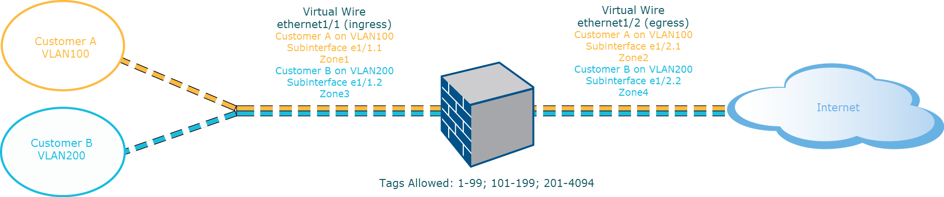
The diagram depicts CustomerA and CustomerB connected to the firewall through one physical interface, ethernet1/1, configured as a Virtual Wire; it is the ingress interface. A second physical interface, ethernet1/2, is also part of the Virtual Wire; it is the egress interface that provides access to the internet.
For CustomerA, you also have subinterfaces ethernet1/1.1 (ingress) and ethernet1/2.1 (egress). For CustomerB, you have the subinterface ethernet1/1.2 (ingress) and ethernet1/2.2 (egress). When configuring the subinterfaces, you must assign the appropriate VLAN tag and zone in order to apply policies for each customer. In this example, the policies for CustomerA are created between Zone1 and Zone2, and policies for CustomerB are created between Zone3 and Zone4.
When traffic enters the firewall from CustomerA or CustomerB, the VLAN tag on the incoming packet is first matched against the VLAN tag defined on the ingress subinterfaces. In this example, a single subinterface matches the VLAN tag on the incoming packet, hence that subinterface is selected. The policies defined for the zone are evaluated and applied before the packet exits from the corresponding subinterface.
The same VLAN tag must not be defined on the parent virtual wire interface and the subinterface . Verify that the VLAN tags defined on the Tag Allowed list of the parent virtual wire interface ( Network > Virtual Wires ) are not included on a subinterface.
Virtual Wire Deployment with Subinterfaces (VLAN Tags and Source IP Sorting)
The diagram depicts CustomerA and CustomerB connected to one physical firewall that has two virtual systems (vsys), in addition to the default virtual system (vsys1). Each virtual system is an independent virtual firewall that is managed separately for each customer. Each vsys has attached interfaces/subinterfaces and security zones that are managed independently.
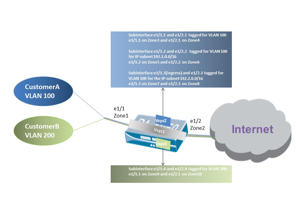
Vsys1 is set up to use the physical interfaces ethernet1/1 and ethernet1/2 as a virtual wire; ethernet1/1 is the ingress interface and ethernet1/2 is the egress interface that provides access to the Internet. This virtual wire is configured to accept all tagged and untagged traffic with the exception of VLAN tags 100 and 200 that are assigned to the subinterfaces.
CustomerA is managed on vsys2 and CustomerB is managed on vsys3. On vsys2 and vsys3, the following vwire subinterfaces are created with the appropriate VLAN tags and zones to enforce policy measures.
| Customer | Vsys | Vwire Subinterfaces | Zone | VLAN Tag | Source IP Info (Classifier) |
|---|---|---|---|---|---|
| A | 2 |
e1/1.1 (ingress)
e1/2.1 (egress) |
Zone3
Zone4 |
100
100 |
None (General VLAN 100 traffic) |
| A | 2 |
e1/1.2 (ingress)
e1/2.2 (egress) |
Zone5
Zone6 |
100
100 |
IP subnet
192.1.0.0/16 |
| A | 2 |
e1/1.3 (ingress)
e1/2.3 (egress) |
Zone7
Zone8 |
100
100 |
IP subnet
192.2.0.0/16 |
| B | 3 |
e1/1.4 (ingress)
e1/2.4 (egress) |
Zone9
Zone10 |
200
200 |
None |
When traffic enters the firewall from CustomerA or CustomerB, the VLAN tag on the incoming packet is first matched against the VLAN tag defined on the ingress subinterfaces. In this case, for CustomerA, there are multiple subinterfaces that use the same VLAN tag (100) . To decide which subinterface to use, the firewall looks at the source IP address in the packet and matches it against the specific IP subnet configured on subinterfaces e1/1.2 and e1/1.3. If the source IP matches one of those subnets, that more specific subinterface is chosen. If it doesn't match either specified subnet but still has VLAN tag 100, it goes to the general subinterface e1/1.1. The policies defined for the chosen zone are then evaluated and applied before the packet exits from the corresponding egress subinterface (e.g., traffic matching e1/1.2 exits via e1/2.2).
For traffic coming back *from* the internet (return-path traffic), the firewall looks at the destination IP address of the packet. It compares this destination IP to the Source IP information defined on the customer-facing subinterfaces (e1/1.2 and e1/1.3 in this case). This helps the firewall send the return traffic back through the correct subinterface pair towards the original source inside Customer A's network.
The same VLAN tag must not be defined on the parent virtual wire interface and the subinterface . Verify that the VLAN tags defined on the Tag Allowed list of the parent virtual wire interface ( Network > Virtual Wires ) are not included on a subinterface.
The following task shows how to configure two Virtual Wire Interfaces ( Ethernet 1/3 and Ethernet 1/4 in this example) to create a virtual wire. The two interfaces must have the same Link Speed and transmission mode ( Link Duplex ) . For example, a full-duplex 1000Mbps copper port matches a full-duplex 1Gbps fiber optic port.
ethernet1/3
in this
example).
ethernet1/3
). (Only interfaces configured as virtual
wire interfaces appear in the list.)
0
to
indicate untagged traffic (such as BPDUs and other Layer 2 control
traffic) is allowed. The absence of a tag implies tag 0. Enter additional
allowed tag integers or ranges of tags, separated by commas (default is
0; range is 0 to 4,094).
ethernet1/4
in
this example) by repeating the preceding steps.
When you select the Virtual Wire object you created, the firewall automatically adds the second virtual wire interface as Interface2 .
internet
).
To allow Layer 3 traffic across the virtual wire, Create a Security Policy Rule to allow traffic from the user zone to the internet zone, and another to allow traffic from the internet zone to the user zone, selecting the applications you want to allow, such as BGP or OSPF.
If you want to be able to apply security policy rules to IPv6 traffic arriving at the virtual wire interface, enable IPv6 firewalling. Otherwise, IPv6 traffic is forwarded transparently.