Palo Alto Networks Virtual Wire (vWire) Interfaces: A Deep Dive for PCNSE
Virtual Wire (vWire) interfaces are a cornerstone of Palo Alto Networks' flexible deployment capabilities, enabling the firewall to be inserted into a network segment with minimal disruption. Operating at Layer 2, a vWire interface pair effectively acts as a "bump in the wire," transparently inspecting all traffic that passes through it. This comprehensive guide explores the intricacies of vWire interfaces, providing the detailed knowledge required for the PCNSE exam and real-world deployments.
Understanding the Transparent Firewall Deployment Model
Traditional firewalls often operate in routed mode (Layer 3), meaning they participate in the network's IP routing, have IP addresses on their interfaces, and often require changes to the existing network's routing tables. In contrast, a Virtual Wire deployment allows the Palo Alto Networks firewall to be inserted into an existing network segment, such as between a switch and a router, or between two switches, without any re-addressing or modification of routing on adjacent devices.
The firewall, configured with a pair of vWire interfaces, inspects all traffic flowing between these two interfaces. Since it's transparent at Layer 2, the connected devices are unaware of the firewall's presence from an IP or MAC addressing perspective (beyond the firewall passing traffic). This makes vWire deployments ideal for situations where network changes must be minimized, such as during initial evaluations, or when protecting specific segments without re-architecting the network.
Figure 1: Basic Virtual Wire deployment. The firewall is inserted transparently between two network devices. Traffic from Router/Switch A to Router/Switch B (and vice-versa) passes through the firewall's vWire interface pair for inspection.
Each vWire interface is bound to a "Virtual Wire object," which logically connects two physical interfaces on the firewall. Traffic entering one interface of the vWire pair is processed by security policies and then exits through the other interface in the pair. No MAC learning or switching decisions are made in the traditional sense; it's a direct bridge with security inspection capabilities.
Key Characteristics and Benefits of vWire
- Transparent Operation: Functions as a Layer 2 bridge, invisible to connected devices from an IP perspective. No IP addresses are assigned to the vWire interfaces themselves for transit traffic.
- Simplified Deployment: Ideal for inserting into existing networks without re-IP addressing or complex routing changes. This "drop-in" capability significantly reduces deployment time and complexity.
-
Full Security Inspection:
Despite its transparency, a vWire deployment supports the full suite of Palo Alto Networks security services, including:
- App-ID: Identifies and controls applications.
- Content-ID: Prevents threats (viruses, spyware, malware) and controls file/data patterns.
- User-ID: Enforces policies based on user identity.
- SSL/TLS Decryption: Inspects encrypted traffic for threats.
- NAT (Network Address Translation): Can perform NAT for traffic traversing the vWire, a powerful feature for transparent deployments needing address translation.
- QoS (Quality of Service): Prioritizes traffic based on policies.
-
VLAN Tag Handling:
Can pass all VLAN tags transparently or be configured with subinterfaces to inspect and apply policies to specific VLANs.
- Default Behavior: Allows all VLAN tagged and untagged traffic.
- Allowed VLANs: Can be configured to explicitly permit only specified VLAN tags through the vWire pair. This is configured on the Virtual Wire object.
- Subinterfaces: Logical interfaces can be created on a physical vWire interface, typically one per VLAN tag. This allows for separate security zones and policies to be applied to traffic on different VLANs passing through the same vWire pair.
- High Availability (HA): Fully supports Active/Passive and Active/Active HA configurations, ensuring resilience and business continuity. Path monitoring for vWire interfaces contributes to failover decisions.
- Link State Pass-Through: If one interface in the vWire pair goes down, the firewall can bring down the other interface in the pair, signaling the link failure to adjacent devices. This is crucial for network convergence.
- No Spanning Tree Protocol (STP) Participation: vWire interfaces do not participate in STP. BPDU (Bridge Protocol Data Units) are typically passed through transparently, allowing STP to function normally on the connected switches.
- LACP Pass-Through: While vWire interfaces can be members of an Aggregate Ethernet (AE) group, the firewall itself does not participate in LACP negotiations. LACPDU packets are passed through transparently.
Configuring Virtual Wire Interfaces
Configuring a vWire involves two main steps: configuring the physical interfaces as type "Virtual Wire" and then creating a "Virtual Wire object" that pairs these interfaces and defines their behavior.
Configuration Path (PAN-OS GUI):
-
Configure Physical Interfaces:
-
Navigate to
Network > Interfaces > Ethernet. -
Select an available physical interface (e.g.,
ethernet1/1). -
In the interface configuration window:
-
Set
Interface Type
to
Virtual Wire. - (Optional) Configure Link Speed/Duplex, MTU, LLDP Profile.
-
Assign to a
Security Zone
(e.g.,
vwire-insideor a more descriptive name). A zone is required for policy enforcement. Note that both interfaces in a vWire pair typically belong to different zones if you want to control traffic between them, or they can be in the same zone if you intend to apply intrazone policies or simply pass traffic. For typical inter-zone inspection, you'd use two zones.
-
Set
Interface Type
to
-
Repeat for the second interface in the pair (e.g.,
ethernet1/2, assigning it to a different zone likevwire-outside).
-
Navigate to
-
Create Virtual Wire Object:
-
Navigate to
Network > Virtual Wires. - Click Add .
-
In the Virtual Wire configuration window:
- Provide a Name for the vWire object.
-
Select
Interface1
(e.g.,
ethernet1/1) and Interface2 (e.g.,ethernet1/2) from the dropdowns. These interfaces must already be configured as type Virtual Wire. -
Tag Allowed (VLANs):
- Leave blank to allow all VLANs (default).
-
Enter specific VLAN IDs (e.g.,
10,20,30-35) to permit only those VLANs. Traffic with other VLAN tags will be dropped.
- Multicast Firewalling: Enable if multicast traffic needs to be controlled by security policies.
- Link State Pass Through: Check this box (recommended) to ensure that if one interface in the pair goes down, the other interface is also brought down administratively. This helps upstream and downstream devices detect the link failure faster.
- (Optional) Configure LLDP PDU Forwarding if specific LLDP behavior is needed. By default, it's passed through.
- Click OK .
-
Navigate to
- Commit Changes.
Figure 2: High-level workflow for configuring a Virtual Wire. Note the distinct steps of interface typing, zone assignment, and vWire object creation.
vWire and VLANs: Subinterfaces
While a basic vWire can pass all VLAN tags transparently or filter based on an allowed list, vWire subinterfaces provide more granular control. By creating subinterfaces, you can logically segment traffic based on VLAN tags and apply different security policies and services to each VLAN.
Each subinterface is associated with a specific VLAN tag. Traffic arriving on the physical vWire interface tagged with that VLAN ID will be directed to the corresponding subinterface for processing.
Configuration Steps for vWire Subinterfaces:
- Ensure the parent physical interfaces are configured as Type: Virtual Wire .
-
Navigate to
Network > Interfaces > Ethernet. -
Select the parent physical interface (e.g.,
ethernet1/1). - Click the Add Subinterface button.
-
In the subinterface configuration:
-
Interface Name:
The name will be like
ethernet1/1.10(where .10 is an example subinterface number, not necessarily the VLAN ID). -
Tag:
Enter the VLAN ID (e.g.,
10) that this subinterface will handle. -
Assign a
Security Zone
. Each subinterface (or pair of subinterfaces across the vWire) can be in its own zone, allowing distinct policy enforcement. For example,
ethernet1/1.10inVLAN10-Trustandethernet1/2.10inVLAN10-Untrust. - (Optional) Assign an MTU, Management Profile.
-
Interface Name:
The name will be like
-
Repeat for all necessary VLANs on both physical interfaces of the vWire pair. For example, if
ethernet1/1.10handles VLAN 10 on one side, you'll typically have a correspondingethernet1/2.10to handle VLAN 10 on the other side. These two subinterfaces would then be associated within a Virtual Wire object that handles VLAN 10. -
When creating/editing the
Virtual Wire object
(
Network > Virtual Wires), you will now select the subinterfaces (e.g.,ethernet1/1.10andethernet1/2.10) as Interface1 and Interface2 instead of the parent physical interfaces if you want policies to apply specifically to that VLAN. If you want some VLANs to be handled by subinterfaces and others passed through the parent vWire, you can have a mix. However, traffic matching a subinterface's VLAN tag will be processed by that subinterface. The parent vWire object's "Tag Allowed" list should include the VLANs handled by subinterfaces.
Figure 3: vWire with VLAN Subinterfaces. Physical interfaces
ethernet1/1
and
ethernet1/2
are configured as vWire type. Subinterfaces are created for VLAN 10 and VLAN 20. Each pair of subinterfaces (e.g.,
ethernet1/1.10
and
ethernet1/2.10
) is bound by a separate Virtual Wire object, allowing distinct zones and policies per VLAN.
Supported Features on Virtual Wire Interfaces
A significant advantage of Palo Alto Networks vWire deployments is the broad range of security features supported, allowing for comprehensive threat prevention even in a transparent mode.
- Application Visibility and Control (App-ID): Full App-ID capabilities allow identification and control of applications passing through the vWire. Policies can be written to allow, deny, or shape application traffic.
- Threat Prevention (Content-ID): Antivirus, Anti-Spyware, Vulnerability Protection, WildFire, DNS Security, and URL Filtering can all be applied to traffic on vWire interfaces.
- User Identification (User-ID): Policies can be enforced based on user or group identity, provided the User-ID agent or other mapping methods can identify users.
- SSL/TLS Decryption: Both inbound and outbound SSL/TLS decryption are supported, enabling inspection of encrypted traffic for threats and sensitive data.
-
Network Address Translation (NAT):
- Source NAT (SNAT): Can change the source IP address of traffic. Useful if the firewall needs to hide internal IP addresses or use a specific IP for outbound connections.
- Destination NAT (DNAT): Can change the destination IP address. Often used to forward traffic to an internal server.
- No-NAT: Can be configured explicitly if NAT is not desired for specific traffic.
- NAT policy rules are evaluated for traffic traversing the vWire.
- Quality of Service (QoS): QoS policies can be applied to prioritize critical applications and manage bandwidth. QoS is applied based on traffic matching QoS policy rules.
- Zone Protection Profiles (ZPP): Can be applied to the security zones associated with vWire interfaces or subinterfaces. However, some protections within ZPPs that rely on IP address validation (e.g., IP spoofing protection) are not effective or applicable in a pure L2 transparent vWire context as the firewall does not have an IP on the vWire interfaces to validate against. Protections like reconnaissance (port scans) or packet-based attacks (oversize IP, etc.) are still effective.
- LLDP (Link Layer Discovery Protocol): vWire interfaces can forward LLDP PDUs, allowing adjacent devices to discover each other. The firewall can also be configured to send its own LLDP information if an LLDP profile is applied to the vWire interface.
- Aggregate Ethernet (AE) Interfaces: Physical interfaces configured as vWire type can be members of an AE group for link redundancy and increased bandwidth. However, the firewall does not participate in LACP negotiations; LACP PDUs are passed through transparently.
- Tunnel Content Inspection: If VPN tunnels (like GRE or IPsec) terminate on devices behind the vWire, the decapsulated traffic can be inspected by the vWire.
- IPv6 Support: vWire interfaces fully support IPv6 traffic inspection and policy enforcement.
Virtual Wire and High Availability (HA)
Virtual Wire deployments integrate seamlessly with Palo Alto Networks High Availability features, ensuring continuous operation in case of a device failure.
-
Active/Passive HA:
- In an A/P HA pair, only the active firewall processes traffic through its vWire interfaces. The passive firewall's vWire interfaces are typically in a standby state but ready to take over.
- Link State: The passive firewall's vWire interfaces can mirror the link state of the active firewall or maintain their own link state based on physical connectivity.
-
LACP in Passive:
The passive firewall can be configured to passively forward LACP PDUs. This helps maintain the LACP bundle with connected switches even when the firewall is passive, speeding up convergence during a failover. If not enabled, the LACP bundle might break and need to re-negotiate post-failover, causing a slightly longer outage.
Configuration:
Device > High Availability > General > Active/Passive Settings > LACP Passive Pre-Negotiation(enable) -
LLDP in Passive:
Similar to LACP, the passive firewall can pre-negotiate LLDP.
Configuration:
Device > High Availability > General > Active/Passive Settings > LLDP Passive Pre-Negotiation(enable) - Path Monitoring for vWire interfaces can be configured to trigger HA failover if the monitored paths become unavailable.
-
Active/Active HA:
- In A/A HA, both firewalls can process traffic, typically based on session ownership or routing. vWire interfaces can participate in A/A HA.
- Careful design is needed to ensure symmetric traffic flows for sessions traversing vWires in an A/A setup.
- Session setup and ownership are critical.
Figure 4: Simplified vWire traffic flow in an Active/Passive HA scenario during normal operation and after a failover. LACP/LLDP pre-negotiation on the passive firewall helps minimize disruption.
Troubleshooting Virtual Wire Deployments
Troubleshooting vWire issues often involves checking Layer 1/2 connectivity, VLAN configurations, and firewall policy/processing.
-
Interface Status:
-
Check physical link status (
show interface hardwareor GUI: Network > Interfaces). Ensure links are up and negotiation is correct. - Verify the vWire object is configured correctly, pairing the intended interfaces (GUI: Network > Virtual Wires).
- Check Link State Pass Through status.
-
Check physical link status (
-
VLAN Tagging:
- If "Tag Allowed" is configured on the vWire object, ensure the expected VLAN tags are listed.
- If using subinterfaces, verify the correct VLAN tag is assigned to each subinterface.
- Use packet captures to confirm if tags are present as expected.
-
Security Policies:
-
Ensure appropriate security policies are in place to allow traffic between the zones assigned to the vWire interfaces/subinterfaces.
Traffic from
Zone_A(on vWire_if1) toZone_B(on vWire_if2) needs a policy allowingSource Zone: Zone_A,Destination Zone: Zone_B. - Check the Traffic Log for denied or dropped packets. The logs will show which rule, if any, matched the traffic.
-
Ensure appropriate security policies are in place to allow traffic between the zones assigned to the vWire interfaces/subinterfaces.
-
Packet Captures:
-
Use the firewall's packet capture utility (
Monitor > Packet Captureor CLI:debug dataplane packet-diag set capture fileand related commands) to see traffic entering and exiting the vWire interfaces. This can help identify if traffic is reaching the firewall, if it's being modified (e.g., by NAT), or if it's leaving the firewall as expected..pcap ... - Filter captures by interface and IP/MAC addresses.
-
Use the firewall's packet capture utility (
-
Global Counters:
-
Check global counters for drops (
show counter global filter packet-filter yes delta yes | match drop). This can indicate issues like flow lookup failures, zone protection drops, etc. -
Specific vWire counters:
show counter interfaceorshow system statistics session | match vwire(for session counts).
-
Check global counters for drops (
-
CLI Commands for vWire:
-
show interface virtual-wire all: Displays status and configuration of all vWire objects. -
show interface: Shows status for the physical interface part of the vWire. -
show VWire [: (Older command, may still show some info).] info -
debug dataplane pool statistics | match VWire: Shows dataplane resource usage related to vWire.
-
- Logging: Ensure logging is enabled for relevant security rules to see traffic hits and actions.
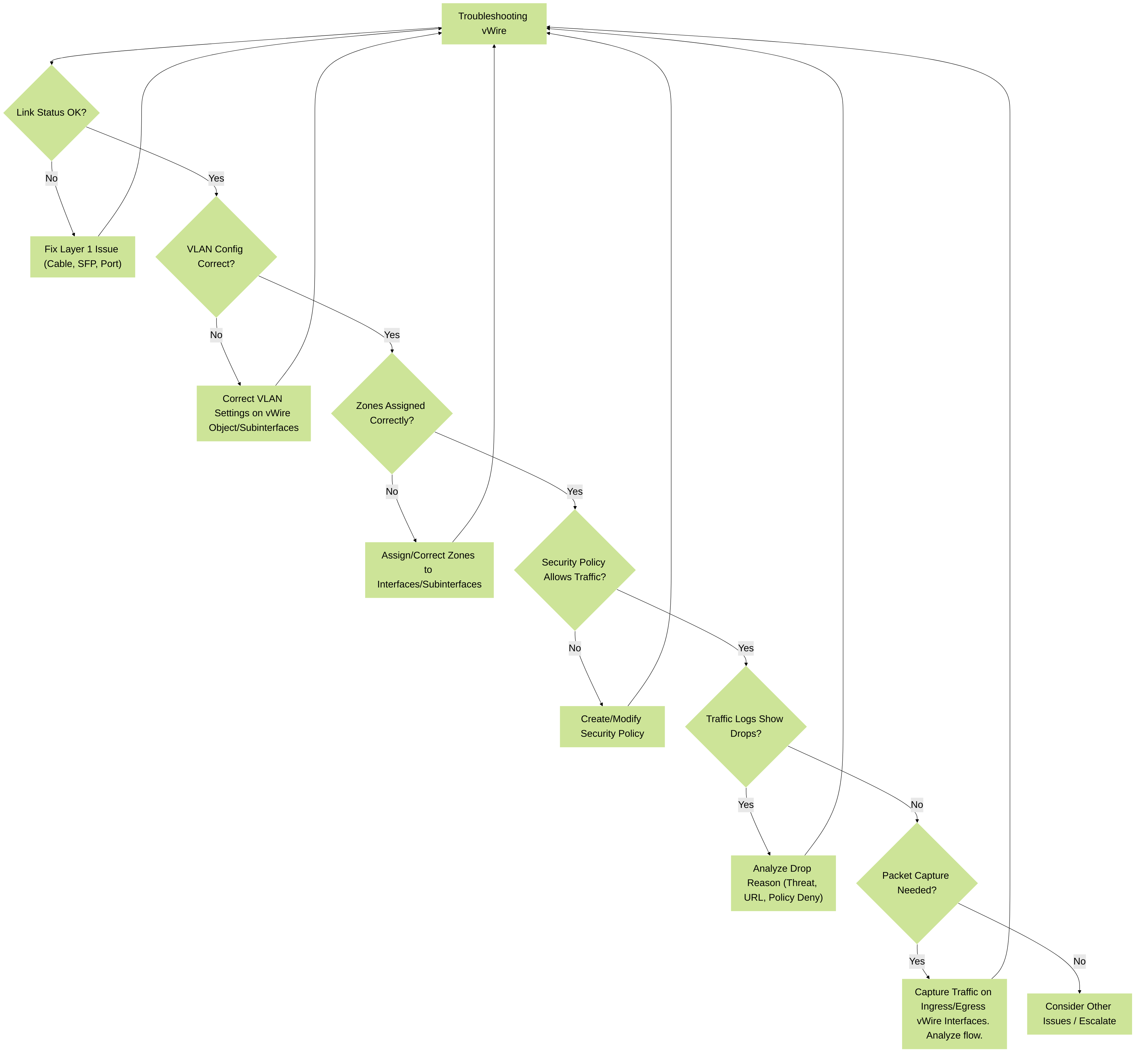
Figure 5: A systematic approach to troubleshooting Virtual Wire issues, starting from physical layer up to policy and advanced diagnostics.
vWire vs. Other Interface Types
Understanding the differences between vWire and other interface types is crucial for choosing the right deployment mode.
| Feature | Virtual Wire (vWire) | Tap | Layer 2 | Layer 3 |
|---|---|---|---|---|
| Primary Mode | Transparent L2 bridge (bump-in-the-wire) | Passive monitoring (receives copy of traffic) | L2 switching, participates in STP, learns MACs | L3 routing, IP addressing, participates in routing protocols |
| IP Address on Interface | No (for transit traffic) | No | No (for L2 forwarding part, can have L3 subinterface for management or routing) | Yes |
| Traffic Blocking | Yes (via Security Policies) | No (read-only) | Yes (via Security Policies) | Yes (via Security Policies) |
| Routing Changes Required | No | No | Minimal (VLANs, STP considerations) | Yes (adjacent routers need to know firewall's IP) |
| MAC Learning | No (simple forwarding between paired interfaces) | No | Yes (builds MAC address table for connected VLANs) | Yes (ARP table for connected subnets) |
| Use Case Example | Transparently inserting firewall, segmenting without re-IP | IDS-like deployment, traffic analysis without inline impact | Replacing an internal switch, L2 segmentation with firewalling | Standard routed firewall (edge, internal segmentation router) |
| NAT Support | Yes | No | Yes (if L3 subinterface involved or policy NAT) | Yes |
| HA Support | Yes (A/P, A/A) | Yes (but passive nature means HA is less critical for inline path) | Yes (A/P, A/A) | Yes (A/P, A/A) |
Table 1: Comparison of Palo Alto Networks Interface Types.
Use Cases and Deployment Scenarios for vWire
- Stealth Deployments: Insert the firewall into the network without altering IP addresses or routing tables, making it invisible to end-users and most network devices.
- Protecting Specific Segments: Quickly add security to a critical network segment (e.g., a server farm, a specific department) by placing the vWire between the segment's switch and its gateway router.
- Proof of Concept (PoC): Easily deploy a firewall for evaluation purposes with minimal impact on the production network.
- Phased Migration: Introduce a Palo Alto Networks firewall into an existing network transparently, then gradually migrate to routed mode if desired.
- Internal Segmentation without Re-IP: Segment internal networks (e.g., between user and server VLANs) that are currently bridged or switched, applying security policies without needing to change IP addressing schemes.
- Inspecting Traffic to a Single Device/Server: Place the vWire directly in front of a critical server to inspect all traffic to and from it.
- Data Center Deployments: Secure East-West traffic flows between server racks or pods.
Limitations and Considerations
- No Routing Protocol Participation: vWire interfaces do not run routing protocols like OSPF or BGP. They are purely Layer 2.
- No IP Address for Transit: While this is a feature, it also means the firewall itself cannot be a gateway for devices connected via vWire in the traditional L3 sense (unless NAT is used to an IP on another interface type). Management traffic can use a service route or management interface.
- IP Spoofing Protection Limited: As mentioned, IP spoofing protection in Zone Protection Profiles is not effective on vWire interfaces.
- Broadcast/Multicast Forwarding: By default, vWire forwards broadcast and unknown multicast traffic. Multicast firewalling can be enabled on the Virtual Wire object for policy control over known multicast groups.
- Performance: While vWire is efficient, all traffic passing through it is subject to inspection, which consumes resources. Ensure the firewall model is appropriately sized for the expected throughput.
- ARP: The firewall does not respond to ARP requests on vWire interfaces for transit traffic. It transparently forwards ARP packets between the connected segments.