Configuration Steps
Part 1: Virtual System and Shared Gateway Setup
-
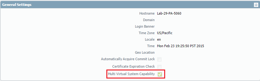
Enable Multi Virtual System Capability:
Verify that this feature is enabled under Device > Setup > General Settings. This is often enabled via licensing.
-
Assign Interfaces to VSYS:
Assign internal interfaces (e.g., ethernet1/2, ethernet1/3) to unique internal virtual systems (vsys2, vsys3). The external interface (e.g., ethernet1/1) should NOT be assigned to a VSYS at this stage; it will be associated with the Shared Gateway implicitly.
Note: Interfaces assigned to the Shared Gateway VSYS (vsys1) effectively become part of the shared resource pool. Interfaces assigned to other VSYS (vsys2, vsys3, etc.) belong exclusively to those virtual systems.
-
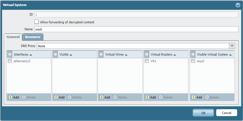
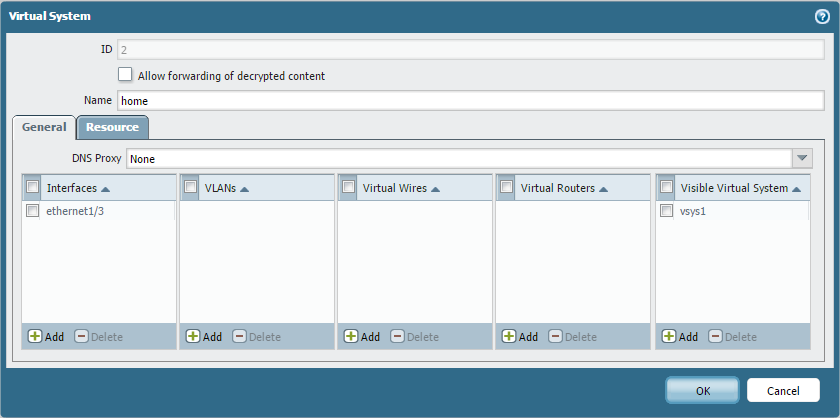
Define Virtual Systems:
Go to Device > Virtual Systems. Create or rename the necessary virtual systems (e.g., vsys1 for Shared_External_GW, vsys2 for WORK_192, vsys3 for HOME_10). Critically, configure the "Visible Virtual Systems" setting for each VSYS to allow it to see the other VSYS it needs to communicate with (both the Shared Gateway and other internal VSYS for Inter-VSYS).
-
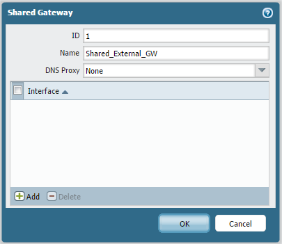
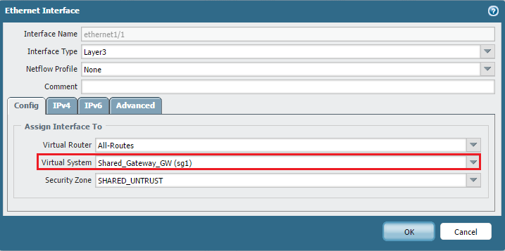
Configure Shared Gateway:
Go to Device > Shared Gateways and click "Add". Give it a name and ID. Then, navigate to Network > Interfaces, select the external interface (ethernet1/1), and assign the Shared Gateway from the "Virtual System" dropdown. This implicitly associates the interface with the Shared Gateway VSYS (vsys1).
-
Verify Interface Assignments:
Check Network > Interfaces to ensure interfaces are correctly assigned to their respective VSYS or the Shared Gateway.

-
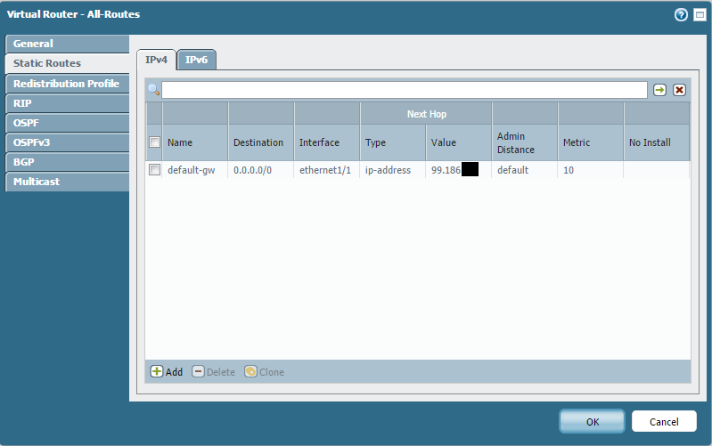
Configure Virtual Router:
All interfaces involved in inter-VSYS routing (both to the shared gateway and between internal VSYS) must be part of the same Virtual Router. The default Virtual Router is typically used. Configure static routes or dynamic routing within this Virtual Router as needed. For basic internet access, a default route pointing to the ISP gateway is sufficient. Note that the Virtual Router itself is not tied to a specific VSYS; it operates across all VSYS interfaces assigned to it.

-
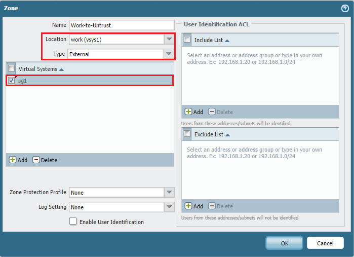
Create External Zones for Shared Gateway:
To allow policy control from internal VSYS to the shared external gateway, you must create External zones *within each internal VSYS*. These zones represent the "exit point" from that internal VSYS towards the shared resource (the external interface). For example, in vsys2 (WORK_192), create a zone named "Work-to-Untrust" with Type set to 'External' and Forwarding to 'SHARED_UNTRUST'. In vsys3 (HOME_10), create "Home-to-Untrust" with Type 'External' and Forwarding to 'SHARED_UNTRUST'.
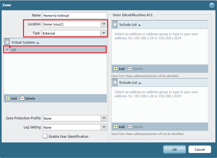 Important PCNSE Concept: External zones are crucial for inter-VSYS policy. A rule in VSYS 'A' allowing traffic to VSYS 'B' will have the Destination Zone set to an *External Zone* defined in VSYS 'A' that forwards to a zone in VSYS 'B'.
 -
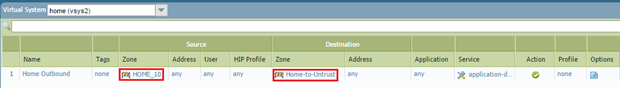
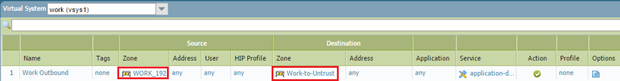
Configure Security Policy for Shared Gateway Access:
Within each internal VSYS, create Security policy rules to allow traffic from the internal zone to the newly created External zone that forwards to the SHARED_UNTRUST zone. For example, in vsys2 (WORK_192), a rule would be 'Source Zone: WORK_192', 'Destination Zone: Work-to-Untrust', Action: Allow (with appropriate app/service/user matching). Repeat this in vsys3. These rules control which traffic from the internal network is permitted to leave towards the shared external interface.
-
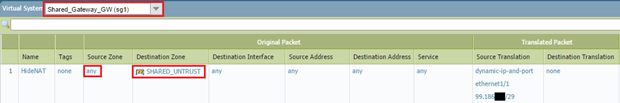
Configure NAT for Shared Gateway Access:
NAT is typically configured within the *Shared External Gateway VSYS* (vsys1), as this is where the external interface resides. Configure a NAT rule to translate the source IP addresses of traffic originating from *any* internal VSYS (or specific VSYS) as it exits the firewall via the shared external interface. A common setup is Source NAT (Hide) using the egress interface IP (ethernet1/1). The source zones for this NAT rule should encompass the internal zones (e.g., WORK_192, HOME_10).
 PCNSE Tip: NAT happens *after* the security policy lookup. When traffic leaves an internal VSYS towards the Shared Gateway VSYS, it's routed by the Virtual Router. The NAT rule in the Shared Gateway VSYS then performs the translation before the packet exits via the external interface.
 -
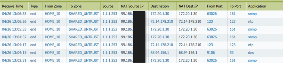
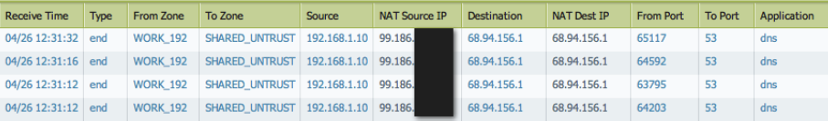
Test Shared Gateway Access:
Generate traffic from hosts in the internal networks (WORK_192, HOME_10) destined for the internet. Monitor the Traffic logs (Monitor > Logs > Traffic) to verify that sessions are allowed by the security policy in their respective internal VSYS and are being NAT'd correctly as they exit via the Shared External Gateway VSYS.
Part 2: Inter-VSYS Communication
To allow traffic between internal VSYS (e.g., from HOME_10 in vsys3 to WORK_192 in vsys2), the process is similar to the Shared Gateway setup, again leveraging External Zones.
-
Create External Zones for Inter-VSYS Communication:
Within each internal VSYS that needs to communicate with *another* internal VSYS, create an External zone that forwards to the zone in the target VSYS.
- In vsys3 (HOME_10), create a zone named "Home-to-Work" with Type 'External' and Forwarding to 'WORK_192' (the zone in vsys2).
- In vsys2 (WORK_192), create a zone named "Work-to-Home" with Type 'External' and Forwarding to 'HOME_10' (the zone in vsys3).
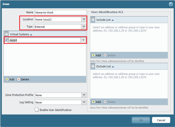
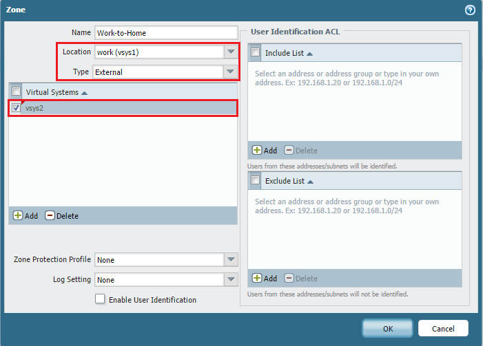
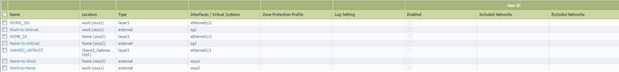
After creating these, the Zone list might look like this (showing zones for Shared Gateway and Inter-VSYS):
-
Configure Security Policy for Inter-VSYS Communication:
Within each internal VSYS, create Security policy rules to allow traffic from its internal zone to the External zone that forwards to the target internal VSYS.
- In vsys3 (HOME_10), create a rule: 'Source Zone: HOME_10', 'Destination Zone: Home-to-Work', Action: Allow (with appropriate app/service/user). This rule allows traffic from the HOME_10 network to be routed towards the WORK_192 network.
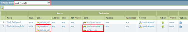
- In vsys2 (WORK_192), create a rule: 'Source Zone: WORK_192', 'Destination Zone: Work-to-Home', Action: Allow (with appropriate app/service/user). This rule allows traffic from the WORK_192 network to be routed towards the HOME_10 network.

 PCNSE Concept: Policy lookup for inter-VSYS traffic happens only once, in the *source* VSYS. The source zone is the internal zone of that VSYS, and the destination zone is the External zone configured to forward to the target VSYS's internal zone.
 -
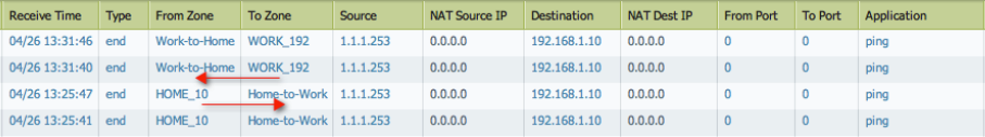
Test Inter-VSYS Communication:
Generate traffic (e.g., pings, application traffic) from hosts in one internal VSYS (e.g., HOME_10) towards hosts in the other internal VSYS (e.g., WORK_192). Monitor the Traffic logs in the *source* VSYS to verify that the sessions are allowed by the inter-VSYS security policy rule.