HA Overview
High availability (HA) is a deployment in which two firewalls are placed in a group or up to 16 firewalls are placed in an HA cluster and their configuration is synchronized to prevent a single point of failure on your network. A heartbeat connection between the firewall peers ensures seamless failover in the event that a peer goes down. Setting up HA provides redundancy and allows you to ensure business continuity.
You can configure two Palo Alto Networks firewalls as an HA pair or configure up to 16 firewalls as peer members of an HA cluster. The peers in the cluster can be HA pairs or standalone firewalls. HA allows you to minimize downtime by making sure that an alternate firewall is available in the event that a peer firewall fails. The firewalls in an HA pair or cluster use dedicated or in-band HA ports on the firewall to synchronize data—network, object, and policy configurations—and to maintain state information.
Firewall-specific configuration such as management interface IP address or administrator profiles, HA specific configuration, log data, and the Application Command Center (ACC) information is not shared between peers.
For a consolidated application and log view across an HA pair, you must use Panorama, the Palo Alto Networks centralized management system. See Context Switch—Firewall or Panorama in the Panorama Administrator’s Guide. Consult the Prerequisites for Active/Passive HA and Active/Active HA .
When a failure occurs on a firewall in an HA pair or HA cluster and a peer firewall takes over the task of securing traffic, the event is called a failover . The conditions that trigger a failover are:
- One or more of the monitored interfaces fail ( Link Monitoring ).
- One or more of the destinations specified on the firewall cannot be reached ( Path Monitoring ).
- The firewall does not respond to heartbeat polls ( Heartbeat Polling ).
- A critical chip or software component fails (packet path health monitoring).
Palo Alto Networks firewalls support stateful active/passive or active/active high availability with session and configuration synchronization with a few exceptions:
- The VM-Series firewall on Azure and VM-Series firewall on AWS support active/passive HA only .
- On AWS, deployment with Amazon Elastic Load Balancing (ELB) does not support HA (ELB provides failover).
- The VM-Series firewall on Google Cloud Platform does not support HA.
It is highly recommended that you use Panorama to provision HA cluster members.
HA Modes
You can set up the firewalls in an HA pair in one of two modes:
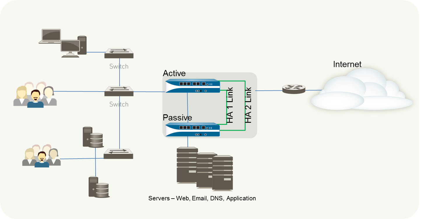
- Active/Passive: One firewall actively manages traffic while the other is synchronized and ready to transition to the active state, should a failure occur. In this mode, both firewalls share the same configuration settings, and one actively manages traffic until a path, link, system, or network failure occurs. When the active firewall fails, the passive firewall transitions to the active state and takes over seamlessly and enforces the same policies to maintain network security. Active/passive HA is supported in the virtual wire, Layer 2, and Layer 3 deployments.
- Active/Active: Both firewalls in the pair are active and processing traffic and work synchronously to handle session setup and session ownership. Both firewalls individually maintain session tables and routing tables and synchronize to each other. Active/active HA is supported in virtual wire and Layer 3 deployments.
In active/active HA mode, the firewall does not support DHCP client. Furthermore, only the active-primary firewall can function as a DHCP Relay. If the active-secondary firewall receives DHCP broadcast packets, it drops them.
An active/active configuration does not load-balance traffic by default. Although you can load-share by sending traffic to the peer (e.g., using ECMP, multiple ISPs, load balancers), the firewalls themselves don't perform load balancing.
When deciding whether to use active/passive or active/active mode, consider the following differences:
- Active/passive mode has simplicity of design; it is significantly easier to troubleshoot routing and traffic flow issues in active/passive mode. Active/passive mode supports a Layer 2 deployment; active/active mode does not.
- Active/active mode requires advanced design concepts that can result in more complex networks. Depending on how you implement active/active HA, it might require additional configuration such as activating networking protocols on both firewalls, replicating NAT pools, and deploying floating IP addresses to provide proper failover. Because both firewalls are actively processing traffic, the firewalls use additional concepts of session owner and session setup to perform Layer 7 content inspection. Active/active mode is recommended if each firewall needs its own routing instances and you require full, real-time redundancy out of both firewalls all the time. Active/active mode has faster failover and can handle peak traffic flows better than active/passive mode because both firewalls are actively processing traffic.
In active/active mode, the HA pair can be used to temporarily process more traffic than what one firewall can normally handle. However, this should not be the norm because a failure of one firewall causes all traffic to be redirected to the remaining firewall in the HA pair. Your design must allow the remaining firewall to process the maximum capacity of your traffic loads with content inspection enabled. If the design oversubscribes the capacity of the remaining firewall, high latency and/or application failure can occur.
In an HA cluster, all members are considered active; there is no concept of passive firewalls except for HA pairs in the clusters, which can keep their active/passive relationship after you add them to an HA cluster.
HA Links and Ports
The firewalls in an HA pair use HA links to synchronize data and maintain state information. Some models of the firewall have dedicated HA ports—Control link (HA1) and Data link (HA2), while others require you to use the in-band ports or management ports as HA links.
- For firewalls with dedicated HA ports, use these ports to manage communication and synchronization between the firewalls.
- For firewalls without dedicated HA ports such as the PA-220 and PA-220R firewalls, as a best practice use the management port for the HA1 port , and use a dataplane port for the HA1 backup . If you use the management port and configured a Permitted IP list, you must add the peer HA1 IP address to the Permitted IP list.
You can configure data ports as both dedicated HA interfaces and as dedicated backup HA interfaces, which is required for firewalls without dedicated HA interfaces.
Data ports configured as HA1, HA2, or HA3 interfaces can be connected directly to each HA interface on the firewall or connected through a Layer 2 switch. For data ports configured as an HA3 interface, you must enable jumbo frames as HA3 messages exceed 1,500 bytes.
For firewalls without dedicated HA ports, decide which ports to use for HA1 and HA1 backup based on your environment and understanding which are the least used and least congested. Assign HA1 to the best interface and HA1 backup to the other one.
HA peers in an HA cluster can be a combination of standalone members and HA pairs. HA cluster members use an HA4 link and HA4 backup link to perform session state synchronization. HA1 (control link), HA2 (data link), and HA3 (packet-forwarding link) are not supported between cluster members that aren’t HA pairs.
HA Link Types
| HA Links and Backup Links | Description |
|---|---|
| Control Link (HA1) |
The HA1 link is used to exchange hellos, heartbeats, and HA state information, and management plane sync for routing, and User-ID information. The firewalls also use this link to synchronize configuration changes with its peer. The HA1 link is a Layer 3 link and requires an IP address.
ICMP is used to exchange heartbeats between HA peers. Ports used for HA1—TCP port 28769 and 28260 for clear text communication; port 28 for encrypted communication (SSH over TCP). If you enable encryption on the HA1 link, you can also Refresh HA1 SSH Keys and Configure Key Options. |
| Data Link (HA2) |
The HA2 link is used to synchronize sessions, forwarding tables, IPSec security associations and ARP tables between firewalls in an HA pair. Data flow on the HA2 link is always unidirectional (except for the HA2 keep-alive); it flows from the active or active-primary firewall to the passive or active-secondary firewall. The HA2 link is a Layer 2 link, and it uses ether type 0x7261 by default.
Ports used for HA2—The HA data link can be configured to use either IP (protocol number 99) or UDP (port 29281) as the transport, and thereby allow the HA data link to span subnets. |
| HA1 and HA2 Backup Links |
Provide redundancy for the HA1 and the HA2 links. In-band ports can be used for backup links for both HA1 and HA2 connections when dedicated backup links are not available. Consider the following guidelines:
|
| Packet-Forwarding Link (HA3) | In addition to HA1 and HA2 links, an active/active deployment also requires a dedicated HA3 link. The firewalls use this link for forwarding packets to the peer during session setup and asymmetric traffic flow. The HA3 link is a Layer 2 link that uses MAC-in-MAC encapsulation. It does not support Layer 3 addressing or encryption. On PA-800 Series, PA-3200 Series, and PA-5200 Series firewalls, you can configure aggregate interfaces as an HA3 link. The aggregate interfaces can also provide redundancy for the HA3 link; you cannot configure backup links for the HA3 link. On PA-3200 Series, PA-5200 Series, PA-5450, and PA-7000 Series firewalls, the dedicated HSCI ports support the HA3 link. The firewall adds a proprietary packet header to packets traversing the HA3 link, so the MTU over this link must be greater than the maximum packet length forwarded. |
| HA4 Link and HA4 Backup Link | The HA4 link and HA4 backup link perform session cache synchronization among all HA cluster members having the same cluster ID. The HA4 link between cluster members detects connectivity failures between cluster members by sending and receiving Layer 2 keepalive messages. View the status of the HA4 and HA4 backup links on the firewall dashboard. |
HA Ports on Palo Alto Networks Firewalls
When connecting two Palo Alto Networks® firewalls in an HA configuration, we recommend that you use the dedicated HA ports. These dedicated ports include: the HA1 ports labeled HA1, HA1-A, and HA1-B used for HA control and synchronization traffic; and HA2 and the High Speed Chassis Interconnect (HSCI) ports used for HA session setup traffic. The PA-5200 Series firewalls have multipurpose auxiliary ports labeled AUX-1 and AUX-2 that you can configure for HA1 traffic.
You can also configure the HSCI port for HA3, which is used for packet forwarding to the peer firewall during session setup and asymmetric traffic flow (active/active HA only). The HSCI port can be used for HA2 traffic, HA3 traffic, or both.
The HA1 and AUX links provide synchronization for functions that reside on the management plane. Using the dedicated HA interfaces on the management plane is more efficient than using the in-band ports as this eliminates the need to pass the synchronization packets over the dataplane.
Whenever possible, connect HA ports directly between the two firewalls in an HA pair (not through a switch or router) to avoid HA link and communications problems that could occur if there is a network issue.
Use the following table to learn about dedicated HA ports and how to connect the HA Links and Backup Links:
| Model | Front-Panel Dedicated Port(s) |
|---|---|
| PA-800 Series Firewalls |
|
| PA-3200 Series Firewalls |
If the firewall dataplane restarts due to a failure or manual restart, the HA1-B link will also restart. If this occurs and the HA1-A link is not connected and configured, then a split brain condition occurs. Therefore, we recommend that you connect and configure the HA1-A ports and the HA1-B ports to provide redundancy and to avoid split brain issues. You can remap the firewall’s SFP ports as HA1-A and HA1-B ports via PAN-OS or Panorama.
The traffic carried on the HSCI ports is raw Layer 1 traffic, which is not routable or switchable. Therefore, you must connect the HSCI ports directly to each other. |
| PA-5200 Series Firewalls |
The HSCI port on the PA-5220 firewall is a QSFP+ port and the HSCI port on the PA-5250, PA-5260, and PA-5280 firewalls is a QSFP28 port. The traffic carried on the HSCI port is raw Layer 1 traffic, which is not routable or switchable. Therefore, you must connect the HSCI ports directly to each other.
|
| PA-5450 Firewall |
The traffic carried on the HSCI ports is raw Layer 1 traffic, which is not routable or switchable. Therefore, you must connect these ports as follows:
You can configure HA2 (data link) on the HSCI ports or on NC data ports. When configuring on dataplane ports, you must ensure that both the HA2 and HA2-Backup links are configured on dataplane interfaces. A mix of a dataplane port and an HSCI port for either HA2 or HA2-Backup will result in a commit failure. |
| PA-7000 Series Firewalls |
You cannot configure an HA1 connection on the NPC data ports or the management (MGT) port.
The traffic carried on the HSCI ports is raw Layer 1 traffic, which is not routable or switchable. Therefore, you must connect these ports as follows:
HA2 and HA2-Backup links can be configured to use a dataplane interface instead of the HSCI ports. However, if configured this way, both the HA2 and HA2-Backup links need to use dataplane interfaces. A mix of a dataplane port and an HSCI port for either HA2 or HA2-Backup will result in a commit failure. This applies to the PA-7050-SMC, PA-7080-SMC, PA-7050-SMC-B, and PA-7080-SMC-B. |
Device Priority and Preemption
The firewalls in an Active-Passive HA pair can be assigned a device priority value to indicate a preference for which firewall should assume the active role. If you need to use a specific firewall in the HA pair for actively securing traffic, you must enable the preemptive behavior on both the firewalls and assign a device priority value for each firewall. The firewall with the lower numerical value, and therefore higher priority , is designated as active. The other firewall is the passive firewall.
The same is true for an Active-Active HA pair; however, the device ID (0 or 1) is used to determine priority. The lower numerical value (Device ID 0) corresponds to a higher priority. The firewall with the higher priority becomes active-primary and the paired firewall becomes active-secondary.
By default, preemption is disabled on the firewalls and must be enabled on both firewalls if desired. When enabled, the preemptive behavior allows the firewall with the higher priority (lower numerical value or Device ID 0) to resume as active or active-primary after it recovers from a failure. When preemption occurs, the event is logged in the system logs.
Failover
When a failure occurs on one firewall and the peer in the HA pair (or a peer in the HA cluster) takes over the task of securing traffic, the event is called a failover . A failover is triggered, for example, when a monitored metric on a firewall in the HA pair fails. The metrics that the firewall monitors for detecting a firewall failure are:
- Heartbeat Polling and Hello messages: The firewalls use hello message and heartbeats to verify that the peer firewall is responsive and operational. Hello messages are sent from one peer to the other at the configured Hello Interval to verify the state of the firewall. The heartbeat is an ICMP ping to the HA peer over the control link, and the peer responds to the ping to establish that the firewalls are connected and responsive. By default, the interval for the heartbeat is 1000 milliseconds. A ping is sent every 1000 milliseconds and if there are three consecutive heartbeat losses, a failover occurs. For details on the HA timers that trigger a failover, see HA Timers .
- Link Monitoring: You can specify a group of physical interfaces that the firewall will monitor (a link group) and the firewall monitors the state of each link in the group (link up or link down). You determine the failure condition for the link group: Any link down or All links down in the group constitutes a link group failure (but not necessarily a failover). You can create multiple link groups. Therefore, you also determine the failure condition of the set of link groups: Any link group fails or All link groups fail, which determines when a failover is triggered. The default behavior is that failure of Any one link in Any link group causes the firewall to change the HA state to non-functional (or to tentative state in active/active mode) to indicate a failure of a monitored object.
- Path Monitoring: You can specify a destination IP group of IP address that the firewall will monitor. The firewall monitors the full path through the network to mission-critical IP addresses using ICMP pings to verify reachability of the IP address. The default interval for pings is 200ms. An IP address is considered unreachable when 10 consecutive pings (the default value) fail. You specify the failure condition for the IP addresses in a destination IP group: Any IP address unreachable or All IP addresses unreachable in the group. You can specify multiple destination IP groups for a path group for a virtual wire, VLAN, or virtual router; you specify the failure condition of destination IP groups in a path group: Any or All , which constitutes a path group failure. You can configure multiple virtual wire path groups, VLAN path groups, and virtual router path groups. You also determine the global failure condition: Any path group fails or All path groups fail, which determines when a failover is triggered. The default behavior is that Any one of the IP addresses becoming unreachable in Any destination IP group in Any virtual wire, VLAN, or virtual router path group causes the firewall to change the HA state to non-functional (or to tentative state in active/active mode) to indicate a failure of a monitored object.
In addition to the failover triggers listed above, a failover also occurs when the administrator suspends the firewall or when preemption occurs.
On PA-3200 Series, PA-5200 Series, PA-5450, and PA-7000 Series firewalls, a failover can occur when an internal health check fails. This health check is not configurable and is enabled to monitor the critical components, such as the FPGA and CPUs. Additionally, general health checks occur on any platform, causing failover.
The following describes what occurs in the event of a failure of a Network Processing Card (NPC) on a PA-7000 Series firewall that is a member of an HA cluster:
- If the NPC that is being used to hold the HA clustering session cache (a copy of the other members’ sessions) goes down, the firewall goes non-functional. When this occurs, the session distribution device (such as a load balancer) must detect that the firewall is down and distribute session load to the other members of the cluster.
- If the NPC of a cluster member goes down and no link monitoring or path monitoring was enabled on that NPC, the PA-7000 Series firewall member will stay up, but with a lower capacity because one NPC is down.
- If the NPC of a cluster member goes down and link monitoring or path monitoring was enabled on that NPC, the PA-7000 Series firewall will go non-functional and the session distribution device (such as a load balancer) must detect that the firewall is down and distribute session load to the other members of the cluster.
LACP and LLDP Pre-Negotiation for Active/Passive HA
If a firewall uses LACP or LLDP, negotiation of those protocols upon failover prevents sub-second failover. However, you can enable an interface on a passive firewall to negotiate LACP and LLDP prior to failover. Thus, a firewall in Passive or Non-functional HA state can communicate with neighboring devices using LACP or LLDP. Such pre-negotiation speeds up failover.
All firewall models except VM-Series firewalls support a pre-negotiation configuration, which depends on whether the Ethernet or AE interface is in a Layer 2, Layer 3, or virtual wire deployment. An HA passive firewall handles LACP and LLDP packets in one of two ways:
- Active: The firewall has LACP or LLDP configured on the interface and actively participates in LACP or LLDP pre-negotiation, respectively.
- Passive: LACP or LLDP is not configured on the interface and the firewall does not participate in the protocol, but allows the peers on either side of the firewall to pre-negotiate LACP or LLDP, respectively.
The following table displays which deployments are supported on Aggregate Ethernet (AE) and Ethernet interfaces.
| Interface Deployment | AE Interface | Ethernet Interface |
|---|---|---|
| LACP in Layer 2 | Active | Not supported |
| LACP in Layer 3 | Active | Not supported |
| LACP in Virtual Wire | Not supported | Passive |
| LLDP in Layer 2 | Active | Active |
| LLDP in Layer 3 | Active | Active |
| LLDP in Virtual Wire | Active |
|
Pre-negotiation is not supported on subinterfaces or tunnel interfaces.
To configure LACP or LLDP pre-negotiation, see the step (Optional) Enable LACP and LLDP Pre-Negotiation for Active/Passive HA for faster failover if your network uses LACP or LLDP in the Active/Passive Setup section.
HA Timers
High availability (HA) timers facilitate a firewall to detect a firewall failure and trigger a failover. To reduce the complexity in configuring timers for an HA pair, you can select from three profiles: Recommended , Aggressive and Advanced . These profiles auto-populate the optimum HA timer values for the specific firewall platform to enable a speedier HA deployment.
Use the Recommended profile for typical failover timer settings and the Aggressive profile for faster failover timer settings. The Advanced profile allows you to customize the timer values to suit your network requirements.
The following table describes each timer included in the profiles and the current preset values (Recommended/Aggressive) across the different hardware models; these values are for current reference only and can change in a subsequent release.
Timers that affect members of an HA cluster are described in Configure HA Clustering documentation.
| Timers | Description | PA-7000/5450/5200/3200 Series | PA-800/220 Series, VM-Series | Panorama |
|---|---|---|---|---|
| Monitor Fail Hold Up Time (ms) | Interval during which the firewall will remain active following a path monitor or link monitor failure. This setting is recommended to avoid an HA failover due to the occasional flapping of neighboring devices. | 0/0 | 0/0 | 0/0 |
| Preemption Hold Time (min) | Time that a passive or active-secondary firewall will wait before taking over as the active or active-primary firewall. | 1/1 | 1/1 | 1/1 |
| Heartbeat Interval (ms) | Frequency at which the HA peers exchange heartbeat messages in the form of an ICMP (ping). | 1000/1000 | 2000/1000 | 2000/1000 |
| Promotion Hold Time (ms) | Time that the passive firewall (in active/passive mode) or the active-secondary firewall (in active/active mode) will wait before taking over as the active or active-primary firewall after communications with the HA peer have been lost. This hold time will begin only after the peer failure declaration has been made. | 2000/500 | 2000/500 | 2000/500 |
| Additional Master Hold Up Time (ms) | Time interval in milliseconds that is applied to the same event as Monitor Fail Hold Up Time (range is 0 to 60,000; default is 500). The additional time interval is applied only to the active firewall in active/passive mode and to the active-primary firewall in active/active mode. This timer is recommended to avoid a failover when both firewalls experience the same link/path monitor failure simultaneously. | 500/500 | 500/500 | 7000/5000 |
| Hello Interval (ms) | Interval in milliseconds between hello packets that are sent to verify that the HA functionality on the other firewall is operational (range is 8,000 to 60,000; default is 8,000). | 8000/8000 | 8000/8000 | 8000/8000 |
| Flap Max |
A flap is counted when:
|
3/3 (Default/Aggressive for all) | ||
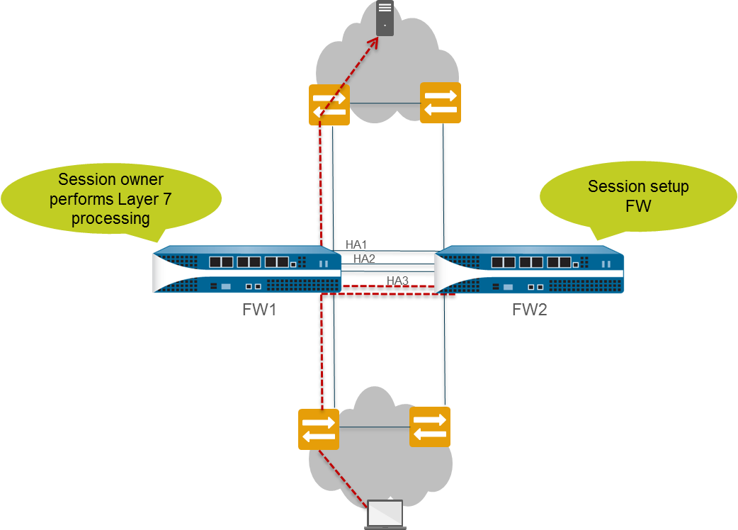
Active/Active Concepts: Session Owner & Setup
In an HA active/active configuration, both firewalls are active simultaneously, which means packets can be distributed between them. Such distribution requires the firewalls to fulfill two functions: session ownership and session setup. Typically, each firewall of the pair performs one of these functions, thereby avoiding race conditions that can occur in asymmetrically routed environments.
Session Owner
You configure the session owner of sessions to be either the firewall that receives the First Packet of a new session from the end host or the firewall that is in active-primary state (the Primary device). If Primary device is configured, but the firewall that receives the first packet is not in active-primary state, the firewall forwards the packet to the peer firewall (the session owner) over the HA3 link.
The session owner performs all Layer 7 processing, such as App-ID, Content-ID, and threat scanning for the session. The session owner also generates all traffic logs for the session.
If the session owner fails, the peer firewall becomes the session owner. The existing sessions fail over to the functioning firewall and no Layer 7 processing is available for those sessions. When a firewall recovers from a failure, by default, all sessions it owned before the failure revert back to that original firewall; Layer 7 processing does not resume.
Palo Alto Networks recommends setting the Session Owner to First Packet and the Session Setup to IP Modulo (or First Packet) unless otherwise indicated in a specific use case. Setting the Session Owner to First Packet reduces traffic across the HA3 link and helps distribute the dataplane load across peers.
Setting Session Owner and Session Setup to Primary Device causes the active-primary firewall to perform all traffic processing. You might want to configure this for one of these reasons:
- You are troubleshooting and capturing logs and pcaps, so that packet processing is not split between the firewalls.
- You want to force the active/active HA pair to function like an active/passive HA pair. See Use Case: Configure Active/Active HA with Floating IP Address Bound to Active-Primary Firewall .
Session Setup
The session setup firewall performs the Layer 2 through Layer 4 processing necessary to set up a new session. The session setup firewall also performs NAT using the NAT pool of the session owner. You determine the session setup firewall in an active/active configuration by selecting one of the following session setup load sharing options.
| Session Setup Option | Description |
|---|---|
| IP Modulo | The firewall distributes the session setup load based on parity of the source IP address. This is a deterministic method of sharing the session setup. |
| IP Hash | The firewall uses a hash of the source and destination IP addresses to distribute session setup responsibilities. |
| Primary Device | The active-primary firewall always sets up the session; only one firewall performs all session setup responsibilities. |
| First Packet | The firewall that receives the first packet of a session performs session setup. |
Recommendations:
- If you want to load-share the session owner and session setup responsibilities, set session owner to First Packet and session setup to IP modulo or First Packet . These are the generally recommended settings.
- If you want to do troubleshooting or capture logs or pcaps, or if you want an active/active HA pair to function like an active/passive HA pair, set both the session owner and session setup to Primary device so that the active-primary device performs all traffic processing.
The firewall uses the HA3 link to send packets to its peer for session setup if necessary. The following figure and text describe the path of a packet that firewall FW1 receives for a new session. The red dotted lines indicate FW1 forwarding the packet to FW2 and FW2 forwarding the packet back to FW1 over the HA3 link.
- The end host sends a packet to FW1.
- FW1 examines the contents of the packet to match it to an existing session. If there is no session match, FW1 determines that it has received the first packet for a new session and therefore becomes the session owner (assuming Session Owner Selection is set to First Packet).
- FW1 uses the configured session setup load-sharing option to identify the session setup firewall. In this example, FW2 is configured to perform session setup.
- FW1 uses the HA3 link to send the first packet to FW2.
- FW2 sets up the session and returns the packet to FW1 for Layer 7 processing, if any.
- FW1 then forwards the packet out the egress interface to the destination.
The following figure and text describe the path of a packet that matches an existing session:
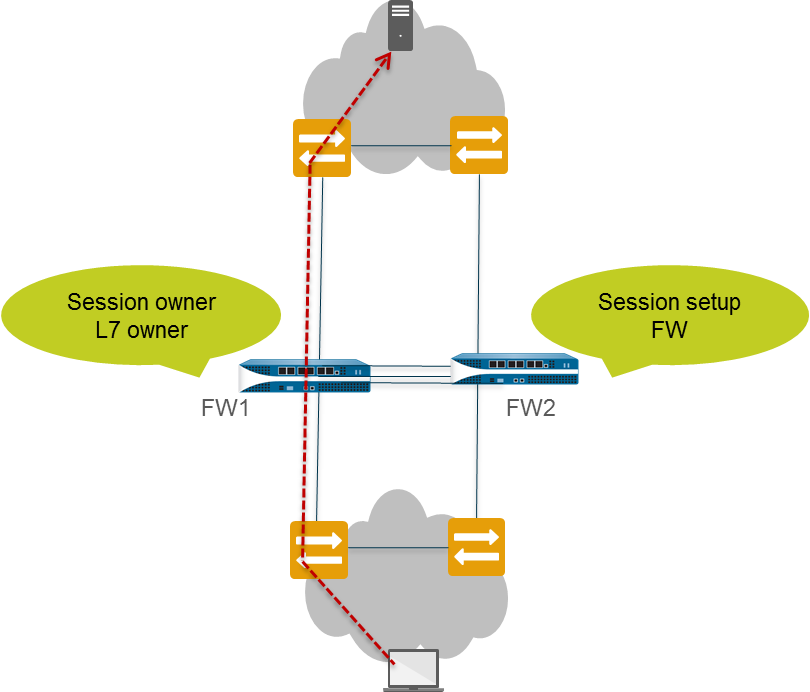
- The end host sends a packet to FW1.
- FW1 examines the contents of the packet to match it to an existing session. If the session matches an existing session, FW1 processes the packet and sends the packet out the egress interface to the destination.
Active/Active Concepts: Floating IP & Virtual MAC Address
In a Layer 3 deployment of HA active/active mode, you can assign floating IP addresses , which move from one HA firewall to the other if a link or firewall fails. The interface on the firewall that owns the floating IP address responds to ARP requests with a virtual MAC address .
Floating IP addresses are recommended when you need functionality such as Virtual Router Redundancy Protocol (VRRP). Floating IP addresses can also be used to implement VPNs and source NAT, allowing for persistent connections when a firewall offering those services fails.
As shown in the figure below, each HA firewall interface has its own IP address and floating IP address. The interface IP address remains local to the firewall, but the floating IP address moves between the firewalls upon firewall failure. You configure the end hosts to use a floating IP address as its default gateway, allowing you to load balance traffic to the two HA peers. You can also use external load balancers to load balance traffic.
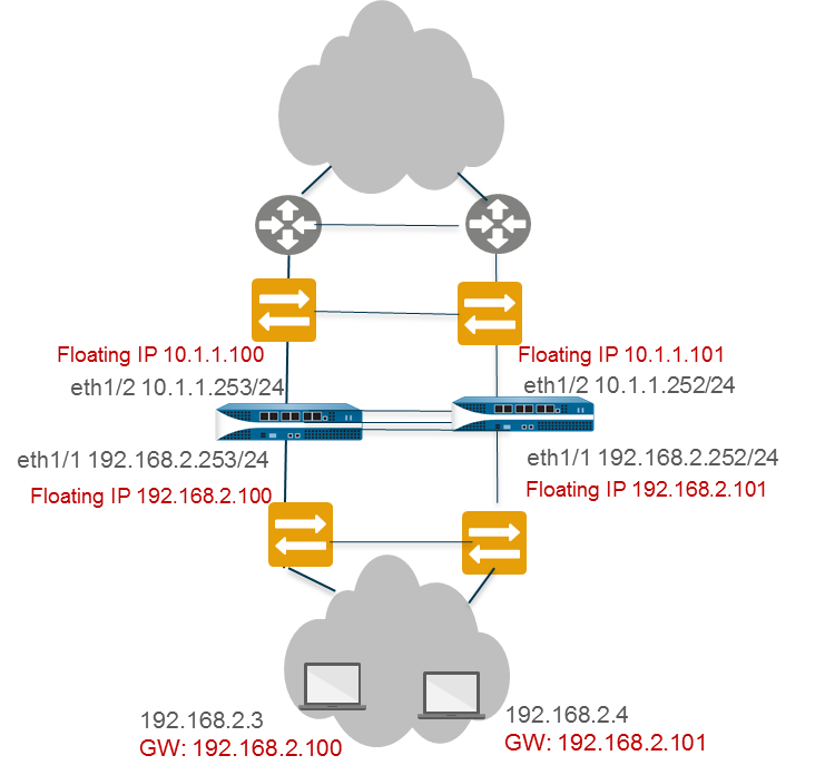
If a link or firewall fails or a path monitoring event causes a failover, the floating IP address and virtual MAC address move over to the functional firewall. (In the figure below, each firewall has two floating IP addresses and virtual MAC addresses; they all move over if the firewall fails.) The functioning firewall sends a gratuitous ARP to update the MAC tables of the connected switches to inform them of the change in floating IP address and MAC address ownership to redirect traffic to itself.
After the failed firewall recovers, by default the floating IP address and virtual MAC address move back to firewall with the Device ID (0 or 1) to which the floating IP address is bound. More specifically, after the failed firewall recovers, it comes on line. The currently active firewall determines that the firewall is back online and checks whether the floating IP address it is handling belongs natively to itself or the other firewall. If the floating IP address was originally bound to the other Device ID, the firewall automatically gives it back. (For an alternative to this default behavior, see Use Case: Configure Active/Active HA with Floating IP Address Bound to Active-Primary Firewall .)
Each firewall in the HA pair creates a virtual MAC address for each of its interfaces that has a floating IP address or ARP Load-Sharing IP address.
The format of the virtual MAC address (on firewalls other than PA-7000, PA-5450, PA-5200, and PA-3200 Series firewalls) is
00-1B-17-00-xx-yy
, where 00-1B-17 is the vendor ID (of Palo Alto Networks in this case), 00 is fixed, xx indicates the Device ID and Group ID as shown in the following table, and yy is the Interface ID:
| 7 | 6 | 5 4 3 2 1 0 | 7 6 5 4 3 2 1 0 |
|---|---|---|---|
| Device-ID | 0 | Group-ID | Interface-ID |
The format of the virtual MAC address on PA-7000, PA-5450, PA-5200, and PA-3200 Series firewalls is
B4-0C-25-xx-xx-xx
, where B4-0C-25 is the vendor ID (of Palo Alto Networks in this case), and the next 24 bits indicate the Device ID, Group ID and Interface ID as follows:
| 7 6 5 | 4 | 3 2 1 0 7 6 | 5 4 3 2 | 1 0 7 6 5 4 3 2 1 0 |
|---|---|---|---|---|
| 111 | Device-ID | Group-ID | 0000 | Interface-ID |
When a new active firewall takes over, it sends gratuitous ARPs from each of its connected interfaces to inform the connected Layer 2 switches of the new location of the virtual MAC address.
Active/Active Concepts: ARP Load-Sharing
In a Layer 3 interface deployment and active/active HA configuration, ARP load-sharing allows the firewalls to share an IP address and provide gateway services. Use ARP load-sharing only when no Layer 3 device exists between the firewall and end hosts , that is, when end hosts use the firewall as their default gateway.
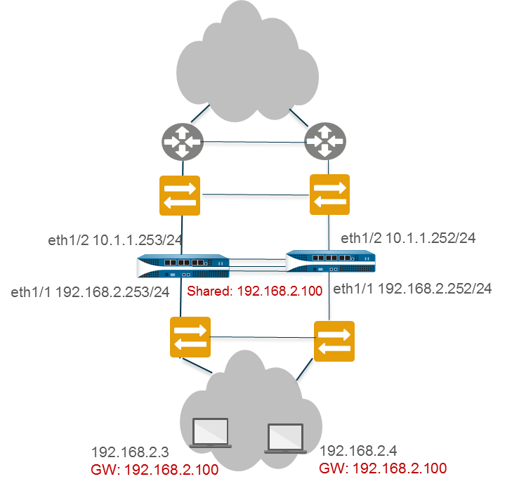
In such a scenario, all hosts are configured with a single gateway IP address. One of the firewalls responds to ARP requests for the gateway IP address with its virtual MAC address. Each firewall has a unique virtual MAC address generated for the shared IP address. The load-sharing algorithm ( IP Modulo or IP Hash ) that controls which firewall will respond to the ARP request is configurable; it is determined by computing the hash or modulo of the source IP address of the ARP request.
After the end host receives the ARP response from the gateway, it caches the MAC address and all traffic from the host is routed via the firewall that responded with the virtual MAC address for the lifetime of the ARP cache. The lifetime of the ARP cache depends on the end host operating system.
If a link or firewall fails, the floating IP address and virtual MAC address move over to the functional firewall. The functional firewall sends gratuitous ARPs to update the MAC table of the connected switches to redirect traffic from the failed firewall to itself.
You can configure interfaces on the WAN side of the HA firewalls with floating IP addresses, and configure interfaces on the LAN side of the HA firewalls with a shared IP address for ARP load-sharing. For example, the figure below illustrates floating IP addresses for the upstream WAN edge routers and an ARP load-sharing address for the hosts on the LAN segment.
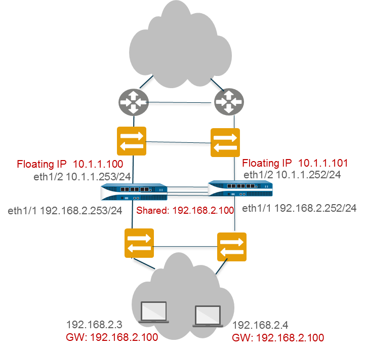
As illustrated in the floating IP address scenario, the firewall supports a shared IP address for ARP load-sharing only on the LAN side of the firewall; the shared IP address cannot be on the WAN side.
Active/Active Concepts: Route-Based Redundancy
In a Layer 3 interface deployment and active/active HA configuration where the firewalls are connected to routers (not directly to end-host segments), route-based redundancy is used. The firewalls use dynamic routing protocols (RIP, OSPF, or BGP) to determine the best path (asymmetric route) and to load share between the HA pair. In such a scenario, no floating IP addresses are necessary .
If a link, monitored path, or firewall fails, or if Bidirectional Forwarding Detection (BFD) detects a link failure, the routing protocol handles the rerouting of traffic to the functioning firewall. You configure each firewall interface with a unique IP address. The IP addresses remain local to the firewall where they are configured; they do not move between devices when a firewall fails.
Active/Active Concepts: NAT and ECMP
NAT in Active/Active HA Mode
In an active/active HA configuration:
- You must bind each Dynamic IP (DIP) NAT rule and Dynamic IP and Port (DIPP) NAT rule to either Device ID 0 or Device ID 1.
- You must bind each static NAT rule to either Device ID 0, Device ID 1, both Device IDs, or the firewall in active-primary state.
Thus, when one of the firewalls creates a new session, the Device ID binding determines which NAT rules match the firewall. The device binding must include the session owner firewall to produce a match.
The session setup firewall performs the NAT policy match, but the NAT rules are evaluated based on the session owner . That is, the session is translated according to NAT rules that are bound to the session owner firewall. While performing NAT policy matching, a firewall skips all NAT rules that are not bound to the session owner firewall.
For example, suppose the firewall with Device ID 1 is the session owner and session setup firewall. When the firewall with Device ID 1 tries to match a session to a NAT rule, it skips all rules bound to Device ID 0. The firewall performs the NAT translation only if the session owner and the Device ID in the NAT rule match.
You will typically create device-specific NAT rules when the peer firewalls use different IP addresses for translation.
If one of the peer firewalls fails, the active firewall continues to process traffic for synchronized sessions from the failed firewall, including NAT traffic. In a source NAT configuration, when one firewall fails:
- The floating IP address that is used as the Translated IP address of the NAT rule transfers to the surviving firewall. Hence, the existing sessions that fail over will still use this IP address.
- All new sessions will use the device-specific NAT rules that the surviving firewall naturally owns. That is, the surviving firewall translates new sessions using only the NAT rules that match its Device ID; it ignores any NAT rules bound to the failed Device ID.
ECMP in Active/Active HA Mode
When an active/active HA peer fails, its sessions transfer to the new active-primary firewall, which tries to use the same egress interface that the failed firewall was using. If the firewall finds that interface among the ECMP paths, the transferred sessions will take the same egress interface and path. This behavior occurs regardless of the ECMP algorithm in use; using the same interface is desirable.
Only if no ECMP path matches the original egress interface will the active-primary firewall select a new ECMP path.
If you did not configure the same interfaces on the active/active peers, upon failover the active-primary firewall selects the next best path from the FIB table. Consequently, the existing sessions might not be distributed according to the ECMP algorithm.
Configuration: Active/Passive HA
Prerequisites for Active/Passive HA
To set up high availability on your Palo Alto Networks firewalls, you need a pair of firewalls that meet the following requirements:
- The same model: Both the firewalls in the pair must be of the same hardware model or virtual machine model. (Verify that by viewing Dashboard, General Information, Model.)
- The same PAN-OS version: Both the firewalls should be running the same PAN-OS version and must each be up-to-date on the application, URL, and threat databases. (Verify that by viewing Dashboard, General Information, Software Version.)
- The same multi virtual system capability: Both firewalls must have Multi Virtual System Capability either enabled or not enabled. When enabled, each firewall requires its own multiple virtual systems licenses. (Verify that by viewing Device > Setup > Management, General Settings, Multi Virtual System Capability enabled or disabled.)
-
The same type of interfaces:
Dedicated HA links, or a combination of the management port and in-band ports that are set to interface type HA. (Verify the following on Device > High Availability > HA Communications.)
- Determine the IP address for the HA1 (control) connection between the HA peers. The HA1 IP address for both peers must be on the same subnet if they are directly connected or are connected to the same switch.
- For firewalls without dedicated HA ports, you can use the management port for the control connection. Using the management port provides a direct communication link between the management planes on both firewalls. However, because the management ports will not be directly cabled between the peers, make sure that you have a route that connects these two interfaces across your network.
- If you use Layer 3 as the transport method for the HA2 (data) connection, determine the IP address for the HA2 link. Use Layer 3 only if the HA2 connection must communicate over a routed network. The IP subnet for the HA2 links must not overlap with that of the HA1 links or with any other subnet assigned to the data ports on the firewall.
- The same set of licenses: Licenses are unique to each firewall and cannot be shared between the firewalls. Therefore, you must license both firewalls identically. If both firewalls do not have an identical set of licenses, they cannot synchronize configuration information and maintain parity for a seamless failover. (Verify that the licenses match by comparing Device > Licenses.)
As a best practice, if you have an existing firewall and you want to add a new firewall for HA purposes and the new firewall has an existing configuration Reset the Firewall to Factory Default Settings on the new firewall. This ensures that the new firewall has a clean configuration. After HA is configured, you will then sync the configuration on the primary firewall to the newly introduced firewall with the clean configuration.
Configuration Guidelines for Active/Passive HA
To set up an active (PeerA) passive (PeerB) pair in HA, you must configure some options identically on both firewalls and some independently (non-matching) on each firewall. These HA settings are not synchronized between the firewalls.
The following settings must be configured identically on both firewalls:
- HA must be enabled.
- The same Group ID value.
- If using in-band ports as HA links, the interfaces for HA1 and HA2 links must be set to type HA.
- HA Mode set to Active Passive.
- If required, enable preemption on both firewalls.
- If required, configure encryption on the HA1 link on both firewalls.
-
Heartbeat Backup enablement (based on HA1/HA1 Backup port types):
- Dedicated HA1 + Dedicated HA1 Backup: Enable Heartbeat Backup.
- Dedicated HA1 + In-band HA1 Backup: Enable Heartbeat Backup.
- Dedicated HA1 + Management Port HA1 Backup: Do NOT enable Heartbeat Backup.
- In-band HA1 + In-band HA1 Backup: Enable Heartbeat Backup.
- Management Port HA1 + In-band HA1 Backup: Do NOT enable Heartbeat Backup.
HA functionality (HA1 and HA1 backup) is not supported on the management interface if it's configured for DHCP addressing (IP Type set to DHCP Client), except on AWS and Azure.
The following table lists the HA settings that you must configure independently on each firewall:
| Independent Configuration Settings | PeerA (Example: Active) | PeerB (Example: Passive) |
|---|---|---|
| Control Link (HA1) IP Address | IP address of the HA1 link configured on this firewall (PeerA). | IP address of the HA1 link configured on this firewall (PeerB). (Must be on the same subnet as PeerA's HA1 if directly connected or same switch). |
| Data Link (HA2) IP Address (if using IP/UDP) | If using IP/UDP transport, IP address for the HA2 link on PeerA. | If using IP/UDP transport, IP address for the HA2 link on PeerB. (Subnet must not overlap HA1 or data ports). |
| Device Priority (required, if preemption is enabled) | Lower numerical value (e.g., 100) for higher priority (active). | Higher numerical value (e.g., 110) for lower priority (passive). |
| Link Monitoring Interfaces | Select physical interfaces on PeerA to monitor. | Select corresponding physical interfaces on PeerB to monitor. |
| Path Monitoring Destinations | Define destination IPs/groups to monitor from PeerA. | Define corresponding destination IPs/groups to monitor from PeerB. |
Configure Active/Passive HA Steps
To configure an active/passive HA pair, first complete the following workflow on the first firewall and then repeat the steps on the second firewall.
- Connect the HA ports physically between the firewalls.
-
Enable ping on the management port (
Device > Setup > Interfaces > Management) if using it for heartbeat backup. -
If not using dedicated HA ports, set data ports to Interface Type
HA
(
Network > Interfaces > Ethernet). -
Set the HA mode to Active/Passive and define the Group ID (
Device > High Availability > General > Setup). -
Set up the HA1 control link connection (
Device > High Availability > HA Communications > Control Link (HA1)). - (Optional) Enable HA1 encryption.
-
Set up the HA1 backup control link (
Device > High Availability > HA Communications > Control Link (HA1 Backup)). -
Set up the HA2 data link connection and backup (
Device > High Availability > HA Communications > Data Link (HA2)). -
Enable heartbeat backup if needed based on HA1/HA1 Backup port types (
Device > High Availability > General > Election Settings > Heartbeat Backup). -
Set device priority and enable preemption if desired (
Device > High Availability > General > Election Settings). -
(Optional) Modify HA Timers (
Device > High Availability > General > Election Settings). -
(Optional) Modify Passive Link State (
Device > High Availability > General > Active Passive Settings). Setting to Auto can speed up failover. -
Enable HA and Config Sync, and define Peer HA1 IPs (
Device > High Availability > General > Setup). -
(Optional) Enable LACP/LLDP Pre-Negotiation (
Network > Interfaces) for faster failover if needed. Requires Passive Link State set to Auto. - Save configuration ( Commit ).
- After configuring both firewalls, verify pairing on the Dashboard (HA Widget) and sync config using Sync to peer on the active firewall.
Define HA Failover Conditions
Configure link monitoring or path monitoring to trigger failover based on network conditions.
-
Configure Link Monitoring (
Device > High Availability > Link and Path Monitoring):- Add Link Group(s), select interfaces, and set group Failure Condition (Any/All).
- (Optional) Modify overall Link Monitoring Failure Condition (Any/All).
-
Configure Path Monitoring (
Device > High Availability > Link and Path Monitoring):- Add Path Group (Virtual Wire, VLAN, or Virtual Router).
- Configure Source IP (if VW/VLAN), Enable, Failure Condition (Any/All), Ping Interval/Count.
- Add Destination IP Group(s) with Destination IPs and Failure Condition (Any/All).
- (Optional) Modify overall Path Monitoring Failure Condition (Any/All).
- Commit changes.
Path monitoring in VLANs is supported only on active/passive pairs. Ensure reachability and source IP configuration before enabling path monitoring.
If using SNMPv3, note the Engine ID is synchronized. VM-Series requires a valid license for a unique Engine ID.
Verify Failover
Test the configuration by triggering a manual failover.
-
Suspend the active firewall (
Device > High Availability > Operational Commands > Suspend local device). - Verify the passive firewall becomes active (Dashboard > HA Widget).
-
Restore the suspended firewall (
Make local device functional). - If preemption is enabled, verify the original active firewall preempts and becomes active again.
Configuration: Active/Active HA
Prerequisites for Active/Active HA
To set up active/active HA on your firewalls, you need a pair of firewalls that meet the following requirements:
- The same model: The firewalls in the pair must be of the same hardware model.
- The same PAN-OS version: The firewalls must be running the same PAN-OS version and must each be up-to-date on the application, URL, and threat databases.
- The same multi virtual system capability: Both firewalls must have Multi Virtual System Capability either enabled or not enabled. When enabled, each firewall requires its own multiple virtual systems licenses.
-
The same type of interfaces:
Dedicated HA links, or a combination of the management port and in-band ports that are set to interface type HA.
- The HA interfaces must be configured with static IP addresses only, not IP addresses obtained from DHCP (except AWS can use DHCP addresses).
- Determine the IP address for the HA1 (control) connection between the HA peers. The HA1 IP address for the peers must be on the same subnet if they are directly connected or are connected to the same switch.
- If you use Layer 3 as the transport method for the HA2 (data) connection, determine the IP address for the HA2 link. Use Layer 3 only if the HA2 connection must communicate over a routed network. The IP subnet for the HA2 links must not overlap with that of the HA1 links or with any other subnet assigned to the data ports on the firewall.
- Each firewall needs a dedicated interface for the HA3 link . See Links & Ports section for model-specific HA3 port details.
- The same set of licenses: Licenses are unique to each firewall and cannot be shared between the firewalls. Therefore, you must license both firewalls identically. If both firewalls do not have an identical set of licenses, they cannot synchronize configuration information and maintain parity for a seamless failover.
If adding a new firewall for HA, reset it to factory defaults first, then sync the configuration from the primary peer after setting up HA.
Configure Active/Active HA Steps (Basic Workflow)
The following procedure describes the basic workflow for configuring your firewalls in an active/active configuration. However, before you begin, review the specific use cases linked below for configuration examples more tailored to your specific network environment.
Remember: Data ports configured as HA3 require jumbo frames enabled.
To configure active/active, first complete the following steps on one peer and then complete them on the second peer, ensuring that you set the Device ID to different values (0 or 1) on each peer.
- Connect HA ports physically (HA1, HA2, HA3, backups).
- Enable ping on the management port.
- If not using dedicated HA ports, set data ports to Interface Type HA .
-
Enable Active/Active HA and set Group ID (
Device > High Availability > General > Setup). -
Set Device ID (0 or 1), enable Config Sync, define Peer HA1 IPs (
Device > High Availability > General > Setup). -
Determine preemption behavior (
Device > High Availability > General > Election Settings). -
Enable heartbeat backup if needed (
Device > High Availability > General > Election Settings). -
(Optional) Modify HA Timers (
Device > High Availability > General > Election Settings). -
Set up the HA1 control link (
Device > High Availability > HA Communications). - (Optional) Enable HA1 encryption.
-
Set up the HA1 backup control link (
Device > High Availability > HA Communications). -
Set up the HA2 data link and backup (
Device > High Availability > HA Communications). -
Configure the HA3 packet forwarding link (
Device > High Availability > HA Communications). -
(Optional) Modify Tentative Hold time (
Device > High Availability > HA Communications). -
Configure Session Owner and Session Setup (
Device > High Availability > HA Communications). -
Configure HA Virtual Addresses if using Floating IPs or ARP Load-Sharing (
Device > High Availability > Active/Active Config). - Configure Floating IP or ARP Load-Sharing settings if using Virtual Addresses.
-
Enable Jumbo Frames if using dataports for HA3 (
Device > Setup > Session). - Define HA Failover Conditions (Link/Path Monitoring).
- Commit the configuration.
- Configure the peer firewall similarly, ensuring a different Device ID.
- Configure NAT rules with appropriate HA Binding if using NAT.
Determine Your Active/Active Use Case
Determine which type of use case you have and then select the corresponding procedure link below for specific configuration steps:
- Use Case: Configure Active/Active HA with Route-Based Redundancy
- Use Case: Configure Active/Active HA with Floating IP Addresses
- Use Case: Configure Active/Active HA with ARP Load-Sharing
- Use Case: Configure Active/Active HA with Floating IP Address Bound to Active-Primary Firewall
- Use Case: Configure Active/Active HA with Source DIPP NAT Using Floating IP Addresses
- Use Case: Configure Separate Source NAT IP Address Pools for Active/Active HA Firewalls
- Use Case: Configure Active/Active HA for ARP Load-Sharing with Destination NAT
- Use Case: Configure Active/Active HA for ARP Load-Sharing with Destination NAT in Layer 3
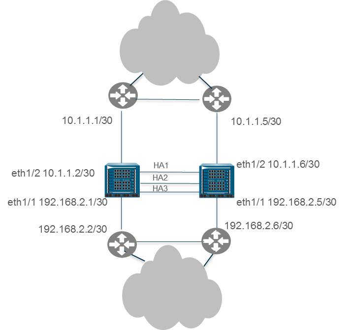
Use Case: Configure Active/Active HA with Route-Based Redundancy
This Layer 3 topology illustrates two PA-7050 firewalls in an active/active HA environment that use Route-Based Redundancy. The firewalls belong to an OSPF area. When a link or firewall fails, OSPF handles the redundancy by redirecting traffic to the functioning firewall.
- Follow steps 1-15 in the basic Active/Active configuration workflow .
- Configure OSPF (or other dynamic routing protocol). See OSPF documentation .
- Define HA Failover Conditions (Link/Path Monitoring).
- Commit the configuration.
- Configure the peer firewall similarly, ensuring a different Device ID (e.g., if the first was 0, use 1 for the peer).
Use Case: Configure Active/Active HA with Floating IP Addresses
In this Layer 3 interface example, the HA firewalls connect to switches and use floating IP addresses to handle link or firewall failures. The end hosts are each configured with a gateway, which is the floating IP address of one of the HA firewalls.
- Follow steps 1-15 in the basic Active/Active configuration workflow .
-
Configure HA Virtual Address(es):
-
Go to
Device > High Availability > Active/Active Config, Add Virtual Address. - Select Interface, IP version, Add IP Address.
- Set Type to Floating .
-
Go to
-
Configure Floating IP settings:
- Do NOT select Floating IP bound to the Active-Primary device (for standard floating IP behavior).
- Set Device 0 Priority and Device 1 Priority to determine ownership (lower value = owner).
- (Optional) Select Failover address if link state is down .
- Click OK.
-
(If needed) Enable Jumbo Frames (
Device > Setup > Session). - Define HA Failover Conditions (Link/Path Monitoring).
- Commit the configuration.
- Configure the peer firewall similarly, ensuring a different Device ID.
Use Case: Configure Active/Active HA with ARP Load-Sharing
This Layer 3 example assumes firewalls are the direct gateway for hosts and uses a shared IP address for ARP Load-Sharing.
- Follow steps 1-15 in the basic Active/Active configuration workflow .
-
Configure HA Virtual Address for ARP Load-Sharing:
-
Go to
Device > High Availability > Active/Active Config, Add Virtual Address. - Select the LAN-facing Interface, IP version, Add the shared IP Address.
- Set Type to ARP Load Sharing .
-
Go to
-
Configure ARP Load-Sharing settings:
- Select Device Selection Algorithm (IP Modulo or IP Hash).
- Click OK.
-
(If needed) Enable Jumbo Frames (
Device > Setup > Session). - Define HA Failover Conditions (Link/Path Monitoring).
- Commit the configuration.
- Configure the peer firewall similarly, ensuring a different Device ID.
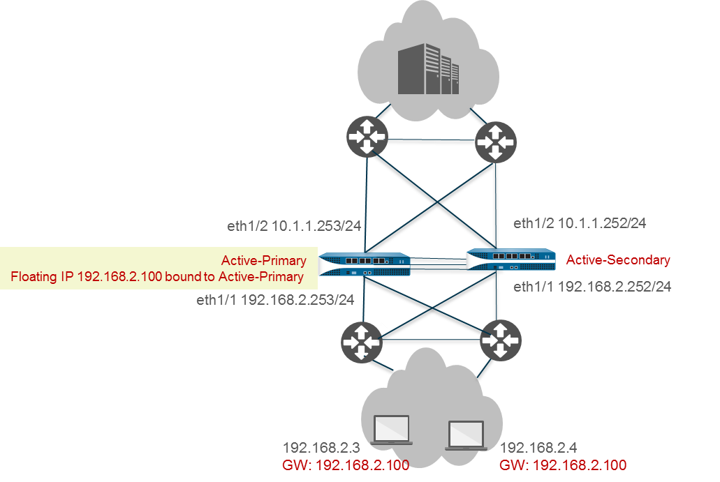
Use Case: Configure Active/Active HA with Floating IP Address Bound to Active-Primary Firewall
This use case makes an A/A pair function like A/P regarding traffic flow by binding the floating IP strictly to the active-primary device. It allows A/A path monitoring benefits while controlling traffic flow.
- Follow steps 1-5 of the basic Active/Active configuration workflow .
-
(Optional but Recommended) Disable Preemption (
Device > High Availability > General > Election Settings). - Follow steps 7-14 of the basic Active/Active configuration workflow.
-
Configure Session Owner and Setup:
-
Go to
Device > High Availability > Active/Active Config > Packet Forwarding. - Set Session Owner Selection to Primary Device .
- Set Session Setup to Primary Device .
- Click OK.
-
Go to
-
Configure HA Virtual Address:
-
Go to
Device > High Availability > Active/Active Config, Add Virtual Address. - Select Interface, IP version, Add the floating IP Address.
- Set Type to Floating .
-
Go to
-
Configure Floating IP settings:
- Select Floating IP bound to the Active-Primary device .
- (Optional) Select Failover address if link state is down .
- Click OK.
-
(If needed) Enable Jumbo Frames (
Device > Setup > Session). - Define HA Failover Conditions (Link/Path Monitoring are strongly recommended here).
- Commit the configuration.
- Configure the peer firewall similarly, ensuring a different Device ID.
You cannot configure NAT for a floating IP address that is bound to an active-primary firewall.
Use Case: Configure Active/Active HA with Source DIPP NAT Using Floating IP Addresses
This Layer 3 example uses source DIPP NAT with floating IPs.
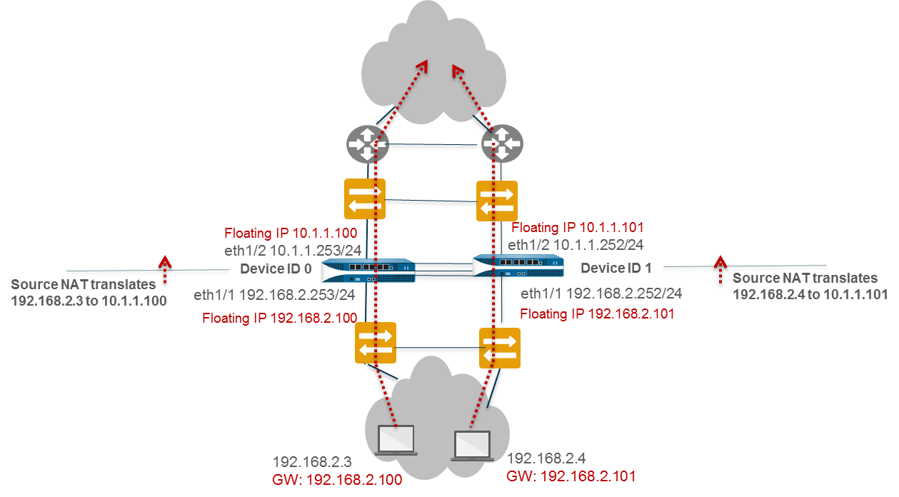
- On Peer B (Device ID 1), follow steps 1-3 of basic A/A config.
- Enable A/A HA, set Group ID, Mode=Active Active, Device ID=1, Peer HA1 IP, Enable Config Sync.
- Follow steps 6-15 of basic A/A config.
- Configure Virtual Address (Floating IP) 10.1.1.101 on eth1/1. Set Type=Floating. Set Device 0/1 Priorities (e.g., Dev1=0, Dev0=255 if Dev1 should own this IP).
- (If needed) Enable Jumbo Frames.
- Define Failover Conditions.
- Commit on Peer B.
- Configure Peer A (Device ID 0) similarly, but with Device ID=0 and Virtual Address 10.1.1.100 on eth1/1, owned by Device 0 (e.g., Dev0=0, Dev1=255).
-
On Peer A (or Peer B, it will sync), create NAT rules:
- Rule 1 (Src-NAT-dev0): Original Packet (Src Zone=Any, Dst Zone=Untrust), Translated Packet (Type=DIPP, Address Type=Interface Address, Interface=eth1/1, IP=10.1.1.100), Active/Active HA Binding=0.
- Rule 2 (Src-NAT-dev1): Original Packet (Src Zone=Any, Dst Zone=Untrust), Translated Packet (Type=DIPP, Address Type=Interface Address, Interface=eth1/1, IP=10.1.1.101), Active/Active HA Binding=1.
- Commit the configuration.
Use Case: Configure Separate Source NAT IP Address Pools for Active/Active HA Firewalls
This example uses separate IP address pools for source NAT, binding each pool to a specific device ID.
- On one HA firewall, create Address Objects for each pool (e.g., Dyn-IP-Pool-dev0 for 10.1.1.140-150, Dyn-IP-Pool-dev1 for 10.1.1.160-170).
-
Create NAT rule for Device ID 0:
-
Policies > NAT > Add. Name: Src-NAT-dev0. - Original Packet: Src Zone=Any, Dst Zone=Untrust.
- Translated Packet: Type=DIPP, Address Type=Translated Address, Add Address Object: Dyn-IP-Pool-dev0.
- Active/Active HA Binding tab: Bind to 0.
- OK.
-
-
Create NAT rule for Device ID 1:
-
Policies > NAT > Add. Name: Src-NAT-dev1. - Original Packet: Src Zone=Any, Dst Zone=Untrust.
- Translated Packet: Type=DIPP, Address Type=Translated Address, Add Address Object: Dyn-IP-Pool-dev1.
- Active/Active HA Binding tab: Bind to 1.
- OK.
-
- Commit the configuration (this will sync to the peer).
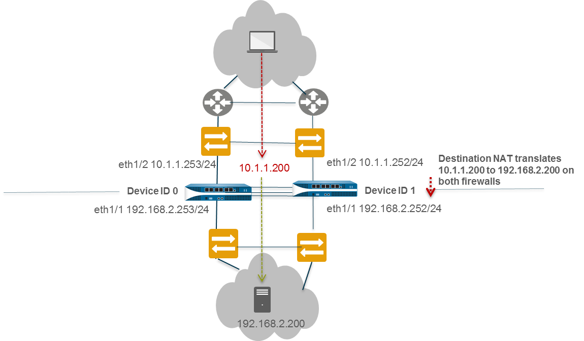
Use Case: Configure Active/Active HA for ARP Load-Sharing with Destination NAT
This Layer 3 example uses ARP Load-Sharing on the LAN and Destination NAT for an internal server. The active-primary firewall handles ARPs for the shared destination NAT address.
- Follow steps 1-3 of basic A/A config on Peer B (Device ID 1).
- Enable A/A HA, set Group ID, Mode=Active Active, Device ID=1, Peer HA1 IP, Enable Config Sync.
- Follow steps 6-15 of basic A/A config.
- Configure HA Virtual Address for ARP Load-Sharing (e.g., 10.1.1.200 on eth1/2, Type=ARP Load Sharing, Algorithm=IP Modulo).
- (If needed) Enable Jumbo Frames.
- Define HA Failover Conditions.
- Commit on Peer B.
- Configure Peer A (Device ID 0) similarly, with Device ID=0.
-
On Peer A (or Peer B, it will sync), create the Destination NAT rule:
-
Policies > NAT > Add. Name: Dst-NAT-ARP-L2. - Original Packet: Src Zone=Any, Dst Zone=Untrust, Dst Address=10.1.1.200.
- Translated Packet: Dst Translation > Translated Address=192.168.1.200 (internal server IP).
- Active/Active HA Binding tab: Bind to primary .
- OK.
-
- Commit the configuration.
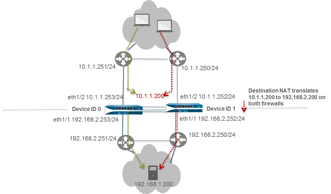
Use Case: Configure Active/Active HA for ARP Load-Sharing with Destination NAT in Layer 3
Similar to the previous case, but requires binding the Destination NAT rule to both Device IDs because traffic can arrive at either firewall from upstream routers.
- Follow steps 1-3 of basic A/A config on Peer B (Device ID 1).
- Enable A/A HA, set Group ID, Mode=Active Active, Device ID=1, Peer HA1 IP, Enable Config Sync.
- Follow steps 6-15 of basic A/A config.
- Configure HA Virtual Address for ARP Load-Sharing (e.g., 192.168.1.1 on eth1/1, Type=ARP Load Sharing, Algorithm=IP Modulo).
- (If needed) Enable Jumbo Frames.
- Define HA Failover Conditions.
- Commit on Peer B.
- Configure Peer A (Device ID 0) similarly, with Device ID=0.
-
On Peer A (or Peer B, it will sync), create the Destination NAT rule:
-
Policies > NAT > Add. Name: Dst-NAT-ARP-L3. - Original Packet: Src Zone=Any, Dst Zone=Untrust, Dst Address=10.1.1.200 (public IP).
- Translated Packet: Dst Translation > Translated Address=192.168.1.200 (internal server IP).
- Active/Active HA Binding tab: Bind to both .
- OK.
-
- Commit the configuration.
Diagrams
Active/Passive Failover
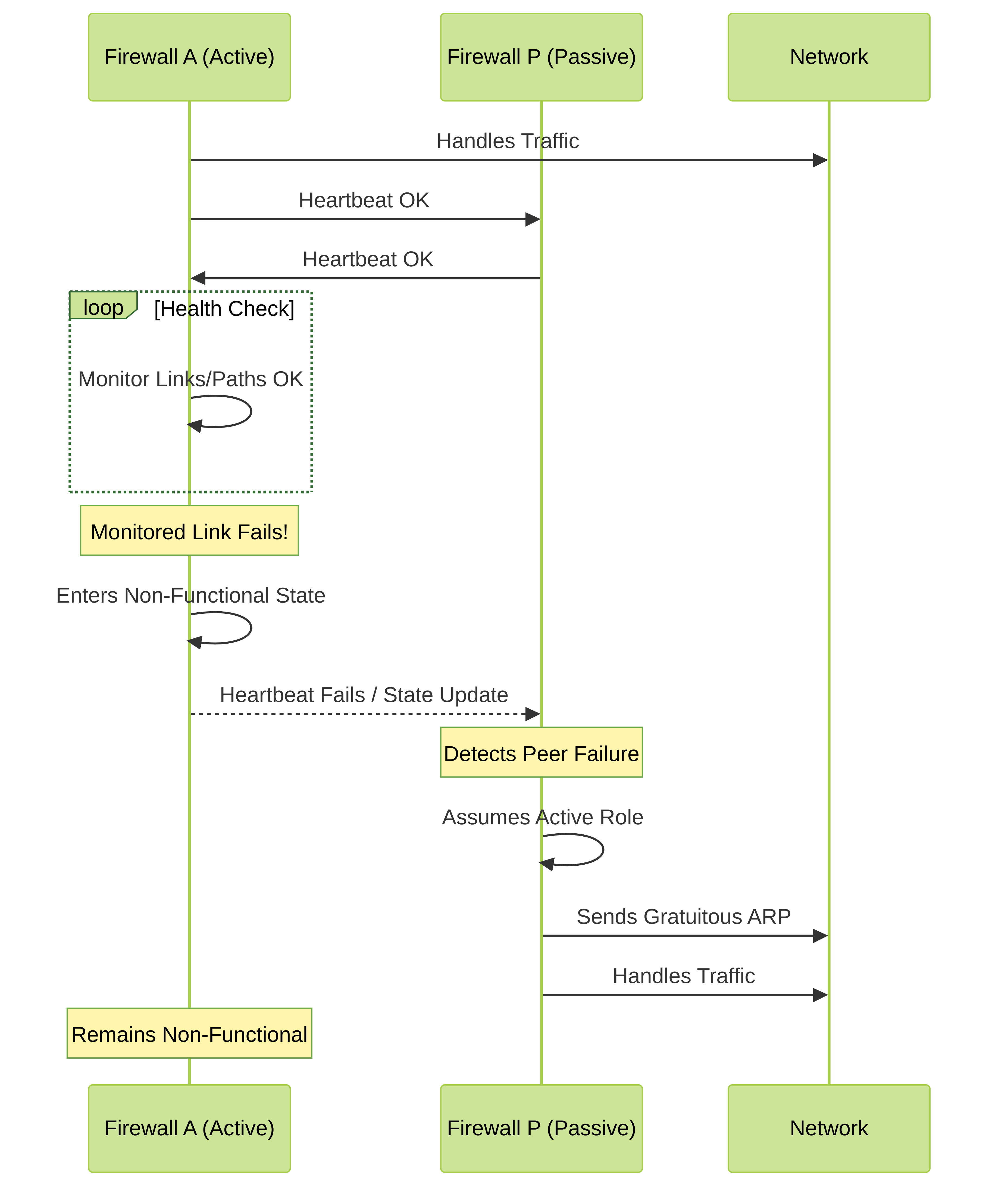
Simplified sequence of an Active/Passive failover triggered by a link failure on the active peer.
Active/Active Session Ownership (First Packet)
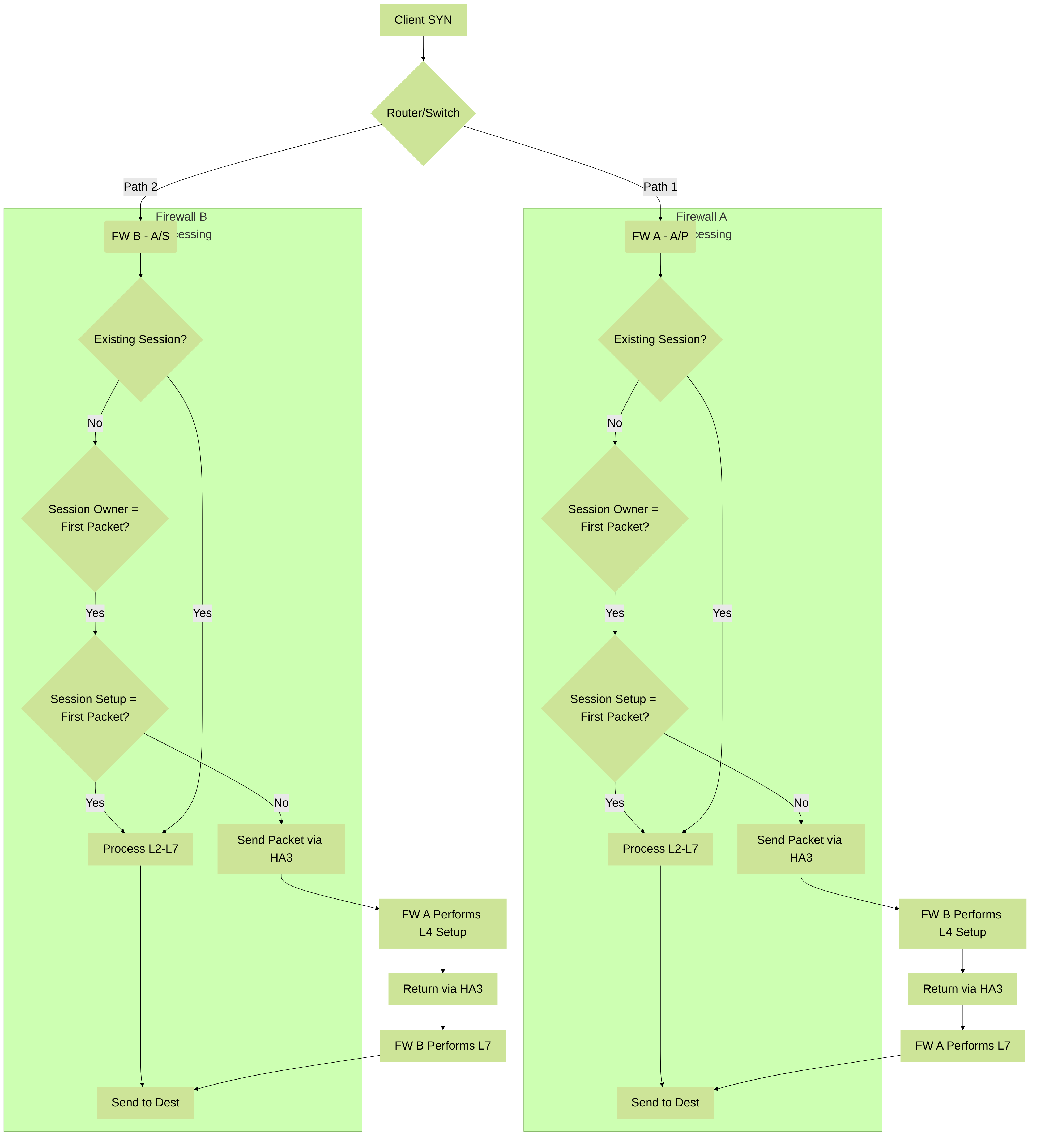
Flowchart showing how session ownership and setup might be split in Active/Active HA when "First Packet" is used for session owner.
High Availability Quiz
Test your understanding of Palo Alto Networks High Availability. Select the best answer for each question.