Palo Alto Networks - Advanced High Availability (HA)
Overview
High Availability (HA) is a critical feature for ensuring network resilience and minimizing downtime. Palo Alto Networks firewalls offer robust HA capabilities, allowing two or more firewalls to operate as a synchronized group, providing seamless failover in case of a device or link failure.
This article explores advanced HA configurations beyond basic setup, focusing on components essential for robust deployments and frequently tested in the PCNSE exam.
Key HA Concepts:
-
HA Modes:
- Active/Passive: One firewall actively processes traffic while the other remains in a passive state, ready to take over if the active unit fails. Configuration and session state are synchronized from active to passive.
- Active/Active: Both firewalls actively process traffic, typically distributing load based on session ownership or routing. Requires more complex network design but offers increased throughput. Session synchronization occurs between both active peers.
- HA Links: Dedicated interfaces used for communication and synchronization between HA peers.
- Failover Triggers: Conditions that cause the passive firewall to become active (or an active peer to become suspended in A/A), such as device failure, link failures, or path monitoring failures.
- Synchronization: Keeping configurations, session states, IPsec SAs, User-ID mappings, etc., consistent between peers.
- Preemption: Allows a firewall with a higher device priority to reclaim the active role after recovering from a failure.
HA Pair Configuration: Pairing Process
Establishing a standard HA pair (typically Active/Passive) involves connecting and configuring two identical firewalls.
Steps:
-
Physical Connections:
- Connect the dedicated HA1 ports between the two firewalls using an appropriate cable (Ethernet for copper HA1, fiber for SFP HA1). This link is primarily for control traffic (heartbeats, config sync, hellos).
- Connect the dedicated or configured HA2 ports between the two firewalls. This link is used for synchronizing session state information, forwarding tables, ARP tables, etc.
- (Optional but Recommended) Connect backup HA1 and HA2 links using different ports/paths for redundancy.
-
Initial HA Configuration (
Device > High Availability > General
):
- Enable HA: Check the box to enable High Availability.
- Group ID: Assign a unique Group ID (1-63) to identify this HA pair. Both firewalls must have the same Group ID.
- Mode: Select the desired mode (e.g., Active/Passive ).
- Peer HA IP Address (HA1): Optionally specify the peer's HA1 IP address for enhanced security (prevents connection from unauthorized devices).
- Enable Config Sync: Check this box to allow configuration synchronization from the active to the passive peer.
- Device Priority: Assign a numerical priority (lower number = higher priority). The firewall with the lower priority number will attempt to become active. Default is usually 100.
- Preemption: Enable this if you want the higher-priority firewall to automatically take back the active role once it recovers from a failure. Configure the Preemption Hold Time (default 1 minute) to allow the recovering firewall time to stabilize before preempting.
- Heartbeat Backup: Enable if you want HA heartbeats to also traverse the HA2 data link if the HA1 link fails.
-
Configure Control Link (HA1):
- Navigate to the HA1 interface ( Network > Interfaces , usually a dedicated port labeled HSCI or HA1-A/B).
- Assign an IP address and netmask (e.g., 192.168.1.1/24 on FW-A, 192.168.1.2/24 on FW-B). These IPs should be in a dedicated, non-routable subnet used only for HA control.
- Configure the backup HA1 link similarly if used.
-
Configure Data Link (HA2):
- Navigate to the HA2 interface (often a standard data port configured for HA type).
- Assign an IP address and netmask in a different subnet from HA1 (e.g., 192.168.2.1/24 on FW-A, 192.168.2.2/24 on FW-B).
- Enable Session Synchronization .
- (Optional) Configure HA2 keep-alives for faster detection of data link failure (consumes more resources).
- Configure the backup HA2 link similarly if used.
-
Configure Packet Forwarding Link (HA3 - Active/Active Only):
- Required only for Active/Active mode. Used to forward packets to the peer that owns the session. Configure on a data port with IP addresses.
-
Commit and Verify:
- Commit the configuration on both firewalls.
-
Verify HA status using the Dashboard widget or CLI commands:
show high-availability stateshow high-availability all - Check for synchronization status (should be synchronized).
HA Pair Configuration: HA Links (HA1, HA2)
Dedicated High Availability (HA) links are essential for communication and synchronization between HA peers. Palo Alto Networks firewalls primarily use HA1 and HA2 links, with HA3 used only in Active/Active mode and HA4 in Clustering.
HA1 Link (Control Link)
- Purpose: Exchanges HA state information, heartbeats, hello messages, and synchronizes configurations (if enabled) and User-ID information between peers. It carries management plane traffic related to HA operation.
- Interface Type: Typically uses dedicated HA ports (HSCI, HA1-A/B) or can be configured on specific data ports set to type 'HA'.
- Connectivity: Requires Layer 2 or Layer 3 connectivity between peers. Must be configured with IP addresses in a dedicated subnet.
- Traffic: Encrypted using IPSec (PAN-OS 7.1+) or SSL/TLS (earlier versions) for security. Unencrypted option available but not recommended.
- Backup: An HA1 backup link using a different port and physical path is highly recommended for redundancy.
HA2 Link (Data Link)
- Purpose: Synchronizes runtime data, primarily session state information, forwarding tables (ARP, MAC, routing), IPSec Security Associations (SAs), etc. Ensures seamless failover for existing sessions.
- Interface Type: Configured on standard data ports (Ethernet/SFP) set to type 'HA'.
- Connectivity: Requires Layer 2 connectivity between peers. Must be configured with IP addresses in a dedicated subnet (different from HA1).
- Traffic: Transmitted in clear text by default (raw Ethernet frames using EtherType 0x7261). Can be optionally encrypted via IPSec tunnels configured between HA2 IPs in newer PAN-OS versions, but this adds overhead.
- Backup: An HA2 backup link is recommended.
- Keep-alives: Optional HA2 keep-alives can be enabled for faster detection of HA2 link failure, but they increase CPU load.
HA Pair Configuration: Timers & Failover Mechanisms
HA timers define the intervals and thresholds for detecting failures and initiating failover. Accurate timer configuration is vital for timely failover without being overly sensitive to transient network issues.
Key HA Timers ( Device > High Availability > General > Election Settings )
- Heartbeat Interval: The frequency (in milliseconds) at which HA peers exchange heartbeat messages over the HA1 control link (and potentially HA2 if Heartbeat Backup is enabled). Default: 1000 ms (1 second).
- Hello Interval: The frequency (in milliseconds) at which HA peers exchange hello messages over the HA1 control link to detect peer reachability. Default: 8000 ms (8 seconds).
- Heartbeat Failures / Peer Unreachable Threshold: The number of consecutive missed heartbeats or hellos before a peer is declared down or unreachable, triggering a failover investigation. Default: 3 misses.
- Promotion Hold Time: The time (in milliseconds) the passive firewall waits after detecting a peer failure before promoting itself to the active state. Allows time for the system to confirm the failure condition. Default: 1000 ms (1 second).
- Preemption Hold Time: The time (in minutes) a higher-priority firewall waits after recovering from a failure before attempting to preempt and take back the active role. Prevents flapping if the firewall is still stabilizing. Default: 1 minute.
Failover Triggers
A failover occurs when the passive firewall determines the active firewall is no longer functional or reachable. Common triggers include:
- Loss of Heartbeats: Failure to receive the configured number of heartbeats from the peer over the HA1 link (and HA2 if backup is enabled).
- HA1 Link Failure: If the primary HA1 link goes down (and the backup, if configured, also fails or is not configured).
- Monitored Interface Failure (Link Monitoring): If monitored data plane interfaces fail according to the configured link group failure condition (e.g., "any" link in the group goes down).
- Monitored Destination Unreachable (Path Monitoring): If monitored IP addresses become unreachable via ICMP ping according to the configured path group failure condition.
- Device Health Failure: Critical system health issues detected by the active firewall's internal monitoring (e.g., data plane failure, critical process failure).
- Manual Suspension: An administrator manually suspends the active firewall ( request high-availability state suspend ).
HA Pair Configuration: Link and Path Monitoring
Beyond heartbeat detection, Link and Path Monitoring provide crucial mechanisms to trigger failovers based on the health of network connections essential for traffic flow.
Configuration is under Device > High Availability > Link and Path Monitoring .
Link Monitoring
- Purpose: Monitors the physical status (link up/down state) of one or more data plane interfaces.
- Mechanism: The firewall checks the operational state reported by the network interface card (NIC).
-
Configuration:
- Create a Link Group .
-
Add specific interfaces (e.g.,
ethernet1/1,ethernet1/2) to the group. -
Define the
Failure Condition:
- Any: Failover occurs if *any* single interface in the group goes down.
- All: Failover occurs only if *all* interfaces in the group go down.
- Enable Link Monitoring under the main HA settings.
- Use Case: Triggering failover if a critical upstream or downstream switch connection fails, even if the firewall device itself is healthy.
Path Monitoring
- Purpose: Monitors the reachability of specific IP addresses across the network by sending ICMP pings.
- Mechanism: The firewall periodically sends ICMP Echo Requests to configured destination IPs from a specified source interface/IP. Failure is determined if responses are not received within a timeout period for a configured number of attempts.
-
Configuration:
- Create a Path Group .
- Add Virtual Routers and specify Source IP/Interface for pings.
- Add Destination IP addresses to monitor (e.g., upstream router, critical server).
- Configure Ping Interval, Count (number of consecutive failures to trigger down state).
-
Define the
Failure Condition:
- Any: Failover occurs if *any* monitored destination IP becomes unreachable.
- All: Failover occurs only if *all* monitored destination IPs become unreachable.
- Enable Path Monitoring under the main HA settings.
- Use Case: Triggering failover if connectivity to a critical next-hop router or essential downstream service is lost, even if the direct physical link is up. Useful for detecting routing issues or upstream device failures beyond the directly connected switch.
Advanced Features: LACP Pre-negotiation
In standard Active/Passive HA, data ports on the passive firewall are typically in a down or standby state. When failover occurs, these ports come up, and protocols like Link Aggregation Control Protocol (LACP) need to negotiate with connected switches, adding delay to traffic restoration.
LACP Pre-negotiation allows interfaces within an Aggregate Ethernet (AE) group on the passive firewall to actively send LACP PDUs and establish LACP bonding before a failover occurs.
Benefits:
- Faster Failover: Significantly reduces traffic downtime during failover as LACP sessions are already established and ready on the newly active firewall. The switch doesn't need to wait for LACP negotiation to complete after the links come up physically.
Configuration Steps:
- Configure AE Interface with LACP: Set up your Aggregate Ethernet interface ( Network > Interfaces > Aggregate Ethernet ) and enable LACP ( LACP tab).
- Enable Passive LACP: On the AE interface's LACP tab, check the option Enable in HA Passive State .
- Set Passive Link State: Navigate to Device > High Availability > General > Active/Passive Settings . Set the Passive Link State dropdown to Auto . This allows interfaces on the passive firewall (including AE members) to come up to negotiate LACP, even though they don't forward data traffic.
- Commit Changes.
Advanced Features: HA Clustering
HA Clustering extends the concept of High Availability by allowing more than two firewalls (up to 16, depending on model) to operate as a single logical cluster, providing enhanced scalability, performance, and redundancy for large-scale deployments.
Key Features & Concepts:
- Increased Scalability & Performance: Distributes traffic processing across multiple active members (in Active/Active cluster mode), significantly increasing throughput capacity.
- Enhanced Redundancy: Provides N+1 or greater redundancy, allowing the cluster to tolerate multiple device failures while maintaining operation.
- Cluster Members: All firewalls within a cluster must be the same hardware model and run the same PAN-OS version .
- Cluster ID: A unique ID assigned to the cluster ( Device > High Availability > HA Clustering ).
- HA4 Links: In addition to HA1 (control) and potentially HA2/HA3 (data/forwarding), clusters use dedicated HA4 interfaces for high-speed session state synchronization among *all* cluster members. HA4 backup links are also recommended.
- Session Distribution & Ownership: Traffic sessions are distributed across active members based on hashing algorithms or session owner assignment. The firewall that initially processes a session becomes its owner.
- Session Synchronization (HA4): The session owner synchronizes the session state (including subsequent packets for that session) to all other members via the HA4 link, ensuring any member can take over if the owner fails.
- Supported Modes: Can operate in Active/Passive or Active/Active configurations *within* the cluster context.
Implementation Steps (High-Level):
- Ensure hardware and software compatibility across all intended members.
- Physically connect HA1, HA2/HA3 (if needed), and HA4 links between all cluster members (often requiring dedicated switches for HA links).
- Configure basic HA settings (Group ID, Mode) on each member.
- Enable HA Clustering ( Device > High Availability > HA Clustering ) on each member, assigning the same Cluster ID.
- Configure HA4 interfaces with appropriate IP addressing in a dedicated subnet.
- Commit changes across all members.
-
Verify cluster formation and health using the dashboard and CLI commands (
show clustering state,show high-availability clustering ...). - Perform thorough failover testing.

Understanding PAN-OS Session Processing: Owner, Setup, Roles & First Packet
Palo Alto Networks firewalls operate primarily as stateful devices. This means they track network connections (sessions) from initiation to termination, applying security policies based on the context of the entire session rather than individual packets. Understanding how sessions are created, assigned to resources, and processed is fundamental to PAN-OS operations and a core topic for the PCNSE exam.
Session Owner
Modern Palo Alto Networks firewalls utilize multi-core processors in their Data Planes (DPs) to handle high traffic loads. To distribute the workload efficiently, incoming sessions are assigned to a specific DP core, which then becomes the "owner" of that session for its entire lifetime.
- Load Distribution: The firewall uses algorithms (often based on hashing source/destination IPs and ports) to distribute new sessions across available DP cores, aiming for balanced utilization.
- Session Pinning: Once a session is assigned to a specific DP core (the Session Owner), all subsequent packets belonging to that same session *must* be processed by that same core. This ensures consistent processing and state management for the session.
- Implications for Asymmetry: If traffic routing is asymmetric (meaning the return path goes through a different firewall or a different interface pair on the same firewall), the firewall might not see both directions of the flow, preventing session establishment or causing issues if the return packet doesn't arrive at the DP core owning the session's forward flow.
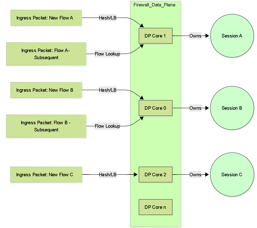
Conceptual Graph: New flows are load-balanced to DP cores (Session Owners). Subsequent packets for an existing session are directed to the owning core.
Session Setup Process (Slow Path)
When the first packet of a new potential flow arrives at the firewall, it needs to determine if the traffic is allowed and, if so, create a new session entry in its state table. This initial processing for a new flow is often referred to as the "slow path" because it involves more lookups and processing steps than handling subsequent packets of an established session ("fast path").
The typical steps involved in the slow path session setup include:
- Ingress Processing: The packet arrives on an ingress interface. Early checks like Zone Protection (including L3/L4 inspection, flood, recon) and potentially DoS Protection policy checks occur. If the packet is dropped here, setup stops.
- Flow Lookup (Session Table): The firewall checks its session table using key packet attributes (source IP, dest IP, source port, dest port, protocol, ingress zone) to see if an existing session matches. For the first packet, this lookup will result in a miss.
- Forwarding Lookup (Route): A route lookup is performed based on the destination IP address to determine the egress interface and next hop.
- NAT Policy Lookup: The firewall checks if any configured NAT policies (Source NAT, Destination NAT) match the packet criteria. If a match occurs, the relevant IP address and/or port translation rules are applied for the session being created.
-
Security Policy Lookup:
This is a critical step. The firewall evaluates its Security Policy rules based on the packet's characteristics (source/dest zone, source/dest IP, application [initially based on port], service, user [if available]) to find a matching rule.
- If no rule matches, the default interzone/intrazone policy action (usually deny) is applied, and session setup stops.
-
If a rule matches with an action of
allow, session setup proceeds. -
If a rule matches with an action of
deny, the packet is dropped, and session setup stops.
- Session Allocation & Installation: If the Security Policy allows the traffic, the firewall allocates resources and installs a new session entry in its session table on the assigned Data Plane core (Session Owner). This entry stores state information, policy results, NAT details, timers, etc.
- Packet Forwarding: The first packet, having successfully passed all checks, is processed (e.g., NAT applied) and forwarded out the determined egress interface.
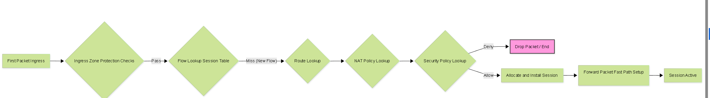
Simplified Flowchart: Session Setup (Slow Path) for the first packet.
Session Role Determination (Client/Server)
For stateful inspection, particularly with TCP, the firewall needs to understand which side initiated the connection (client) and which side is responding (server). This role determination is crucial for correctly interpreting TCP sequence numbers, state transitions, and applying policies that might differentiate based on role.
- TCP Role Determination: This is straightforward. The firewall identifies the client as the host that sends the initial TCP SYN packet. The host receiving the SYN and responding with a SYN-ACK is identified as the server.
- UDP/ICMP Role Determination: For connectionless protocols like UDP and ICMP, there isn't an explicit handshake like TCP's SYN/SYN-ACK. The firewall typically assumes the host sending the *first* packet seen for a potential UDP or ICMP "session" is the client, and the recipient is the server. This assumption is generally reliable but can be less definitive than TCP.
-
Importance:
Knowing client vs. server role is vital for:
- Applying security policies correctly (e.g., allowing established connections back from server to client).
- Accurate state tracking (e.g., TCP windowing, sequence numbers).
- Potential application of different security profiles based on traffic direction (though less common than applying profiles to the whole session).
- Troubleshooting asymmetric routing issues.
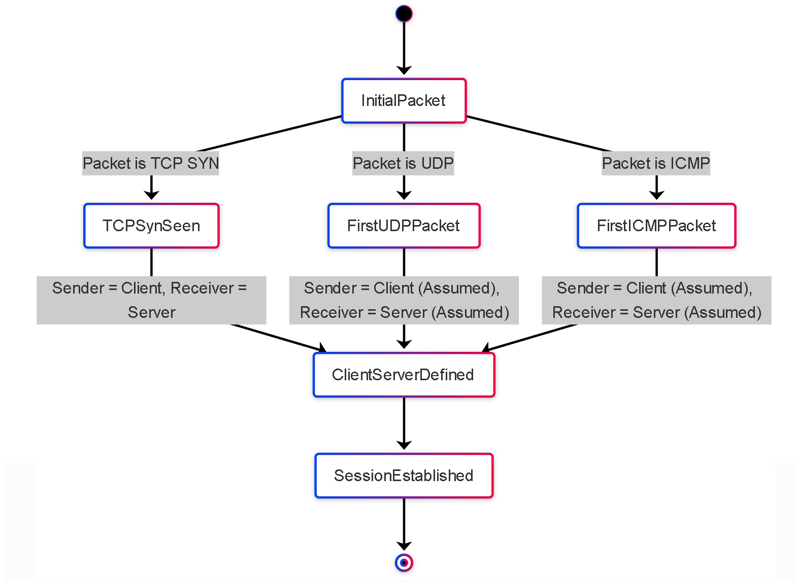
Simplified State Diagram: How the first packet determines client/server roles.
First Packet Processing Summary
Combining these concepts, the journey of the first packet of a new flow involves:
- Packet arrival at the ingress interface.
- Ingress Zone Protection checks.
- Flow lookup miss (triggering slow path).
- Assignment to a Data Plane core (Session Owner determination).
- Route lookup on the assigned DP core.
- NAT policy lookup on the assigned DP core.
- Client/Server role determination (based on TCP SYN or first packet for UDP/ICMP).
- Security policy lookup on the assigned DP core.
- If allowed, session installation in the session table on the owning DP core.
- Packet modification (e.g., NAT) and forwarding.
Subsequent packets matching the installed session entry will take the fast path, directly processed by the Session Owner DP core based on the established state and policy decisions.
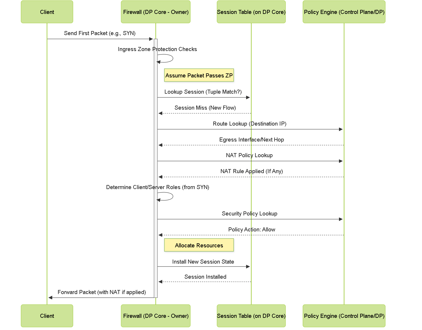
Sequence Diagram: Processing the first packet (Slow Path).
Diagrams: HA Concepts
Sequence Diagram: Basic Active/Passive Failover (Link Monitor Trigger)
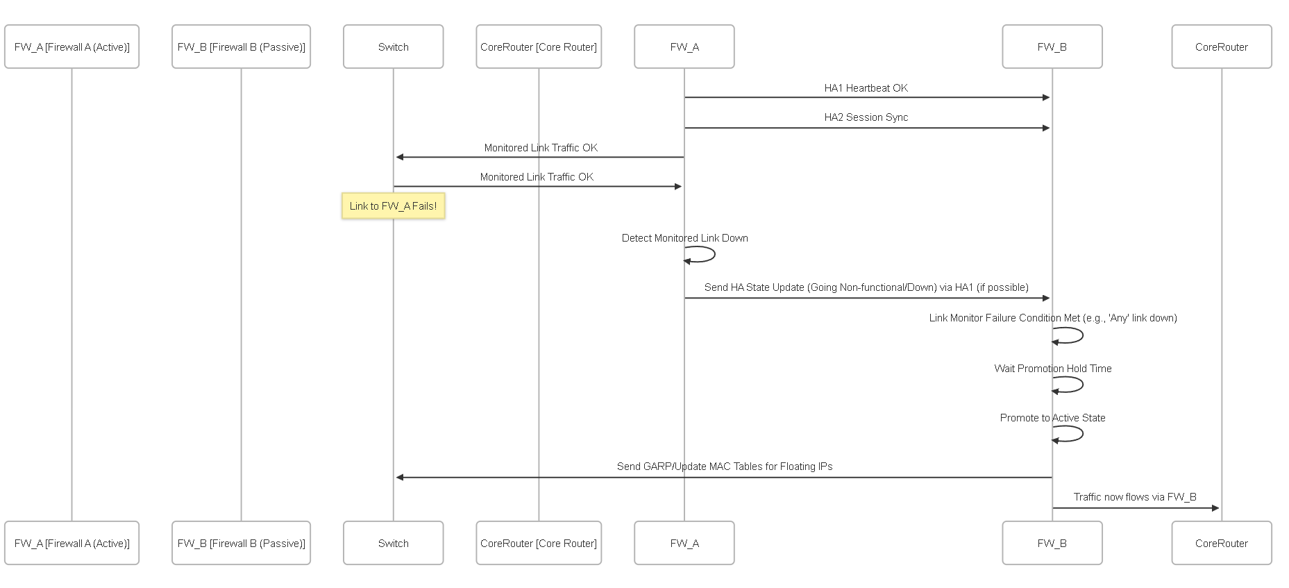
Simplified sequence of an Active/Passive failover triggered by a monitored link failure.
Flowchart: Failover Decision Logic
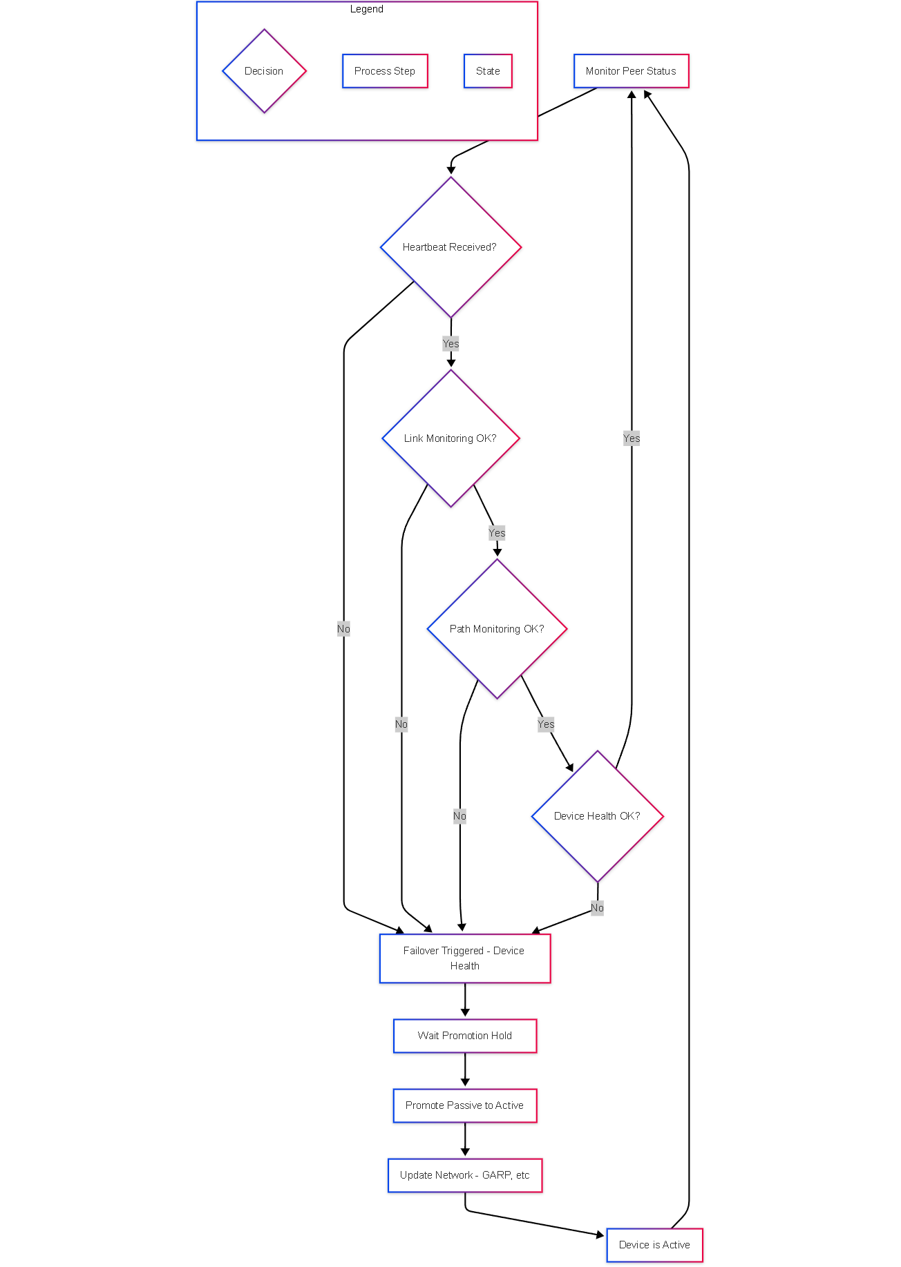
Simplified decision flowchart for HA failover triggers on a passive device.
Graph: HA Components Relationship (Active/Passive)
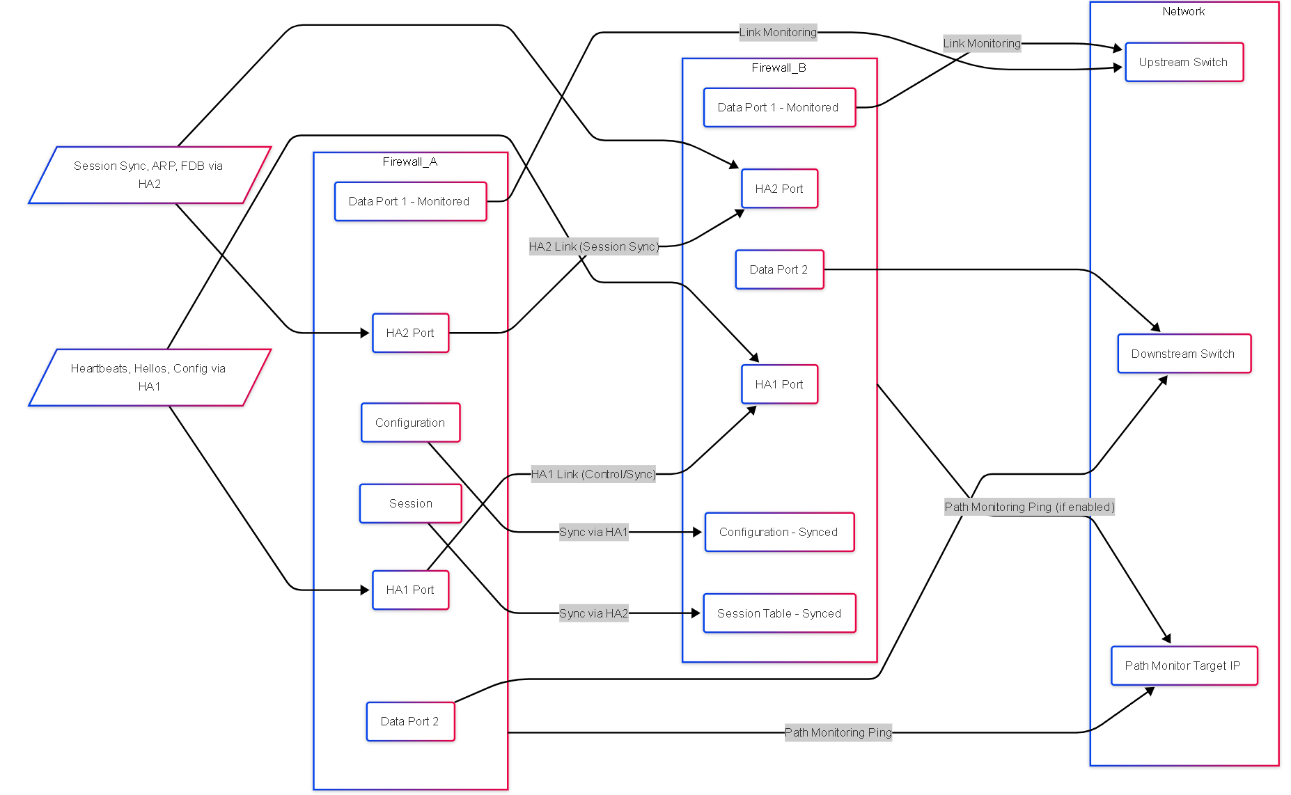
Relationship between HA components in an Active/Passive pair with link and path monitoring.
State Diagram: HA Peer States
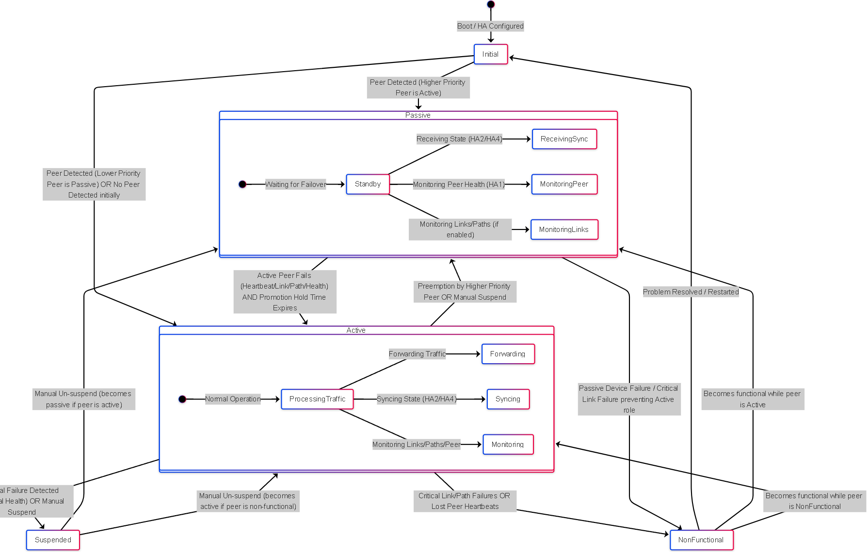
Simplified state diagram showing common HA peer states and transitions.
PCNSE Exam Focus Points
Key High Availability concepts frequently tested on the PCNSE exam:
- HA Modes: Understand the fundamental differences between Active/Passive and Active/Active operation, including traffic flow, session synchronization, and typical use cases.
-
HA Links:
Know the purpose of each link:
- HA1 (Control Link): Heartbeats, Hellos, Config Sync, User-ID Sync, HA State info. (Layer 3 required).
- HA2 (Data Link): Session State Sync, Forwarding Table Sync (ARP, MAC, Route), IPsec SA Sync. (Layer 2 required).
- HA3 (Packet Forwarding - A/A Only): Forwards packets to the session owner peer.
- HA4 (Clustering Only): Session state sync between all cluster members.
- HA Timers: Understand the role of key timers: Heartbeat Interval, Hello Interval, Promotion Hold Time, Preemption Hold Time. Know their default values (often tested) and implications of changing them.
- Failover Triggers: Be able to identify common triggers: Heartbeat loss, HA1 link failure, monitored link failure (Link Monitoring), monitored path failure (Path Monitoring), device health failure (internal monitoring), manual suspension.
- Link & Path Monitoring: Differentiate between monitoring physical link state (Link Monitoring) vs. reachability via ICMP (Path Monitoring). Understand the 'Any' vs 'All' failure conditions.
- Synchronization: Know what gets synchronized over HA1 (config, User-ID) vs. HA2 (sessions, forwarding tables, IPsec SAs).
- Preemption: Understand its purpose (allow higher priority FW to become active again) and the role of the Preemption Hold Time.
- LACP Pre-negotiation: Know its benefit (faster failover for AE links in A/P), the required settings ('Enable in HA Passive State' on AE interface, 'Passive Link State = Auto' globally), and its limitations (not on VM-Series).
- HA Clustering: Understand the basic concept (multiple FWs as one), the need for identical models/OS, and the role of HA4 links for session synchronization.
-
Troubleshooting Commands:
Be familiar with basic CLI commands for verification:
-
show high-availability state(Overall status) -
show high-availability all(Detailed status, timers, counters) -
show high-availability link-monitoring -
show high-availability path-monitoring -
show high-availability clustering ...(For clustering)
-
- Floating IPs & VRRP: While not detailed here, understand how floating IPs move during failover and how VRRP can be used as an alternative or supplement in specific designs.
- Session Setup Settings: Understand how TCP SYN+ACK session setup options interact with HA failover.
High Availability Knowledge Check (PCNSE Style)
Test your understanding of Palo Alto Networks HA concepts.