Advanced Routing Overview
PAN-OS ® provides an Advanced Routing Engine that allows the firewall to scale and provide stable, high-performing, and highly available routing functions to large data centers, ISPs, enterprises, and cloud users. The Advanced Routing Engine simplifies operations with a standards-based configuration, which reduces your learning curve since it is similar to that of other router vendors. Protocol configuration profiles and a granular filtering profile work across multiple logical routers and virtual systems. Route redistribution is simplified with a redistribution profile. BGP peer groups and peers can inherit configuration to make BGP more agile.
The Advanced Routing Engine supports static routes, BGP, MP-BGP, OSPFv2, OSPFv3, RIPv2, IPv4 multicast routing, BFD, redistribution, route filtering into the RIB, access lists, prefix lists, and route maps.
Use the Advanced Routing Engine Migration Reference to plan your migration from the legacy routing engine and to see the differences between the legacy and advanced routing engines and the exceptions.
The following models support the Advanced Routing Engine:
- PA-7000 Series
- PA-5400 Series
- PA-5200 Series
- PA-3400 Series
- PA-3200 Series
- PA-1400 Series
- PA-400 Series
- CN-Series
- VM-Series
- M-700 appliance
- M-600 appliance
- M-300 appliance
- M-200 appliance
Logical Router Overview
Core Functionality
The firewall uses logical routers (LRs) for Layer 3 routing to other subnets. They learn routes through defining static routes manually or participating in dynamic routing protocols.
Routes populate the **Routing Information Base (RIB)**. For forwarding, the best route from the RIB is placed in the **Forwarding Information Base (FIB)**. For ECMP , all equal-cost routes go into the FIB.
For devices on the same IP subnet, the firewall uses **Ethernet switching**.
Interfaces and Packet Processing
Ethernet, VLAN, and tunnel interfaces handle Layer 3 packets. The destination zone is determined by the outgoing interface based on forwarding decisions.
The firewall consults **policy rules** based on the destination zone to apply security policies.
Multiple Logical Routers
You can create multiple logical routers, each with a separate set of routes. This allows different routing behaviors for different interfaces and network segments.
You can Configure Layer 3 Interfaces to work with dynamic routing protocols (BGP, OSPF, OSPFv3, RIP) and static routes. Each Layer 3 interface must be associated with **one** logical router.
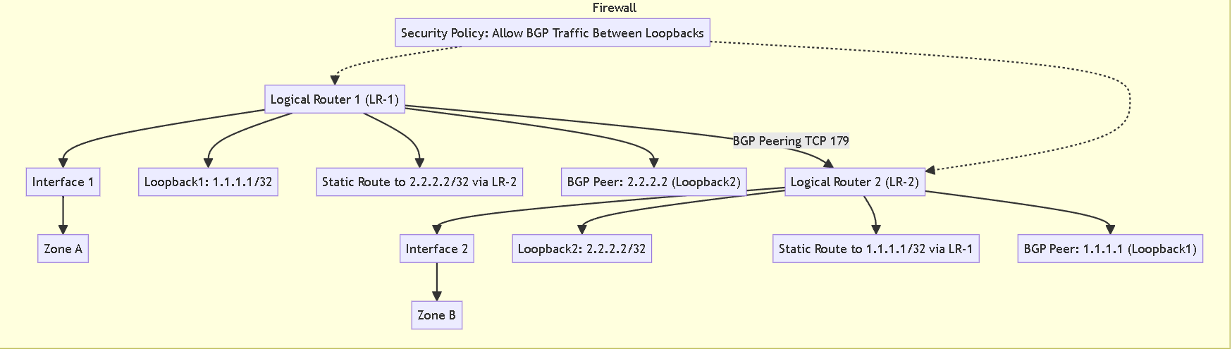
Routing Between Logical Routers (Inter-LR Routing)
Logical routers can route to other logical routers within the same firewall.
Configuring dynamic routing between LRs involves creating a **loopback interface** in each LR, a **static route** between the loopbacks (often with a "next-lr" type), and configuring a **dynamic routing protocol** (like BGP peering over the loopbacks). Security policies must permit this inter-LR routing protocol traffic.
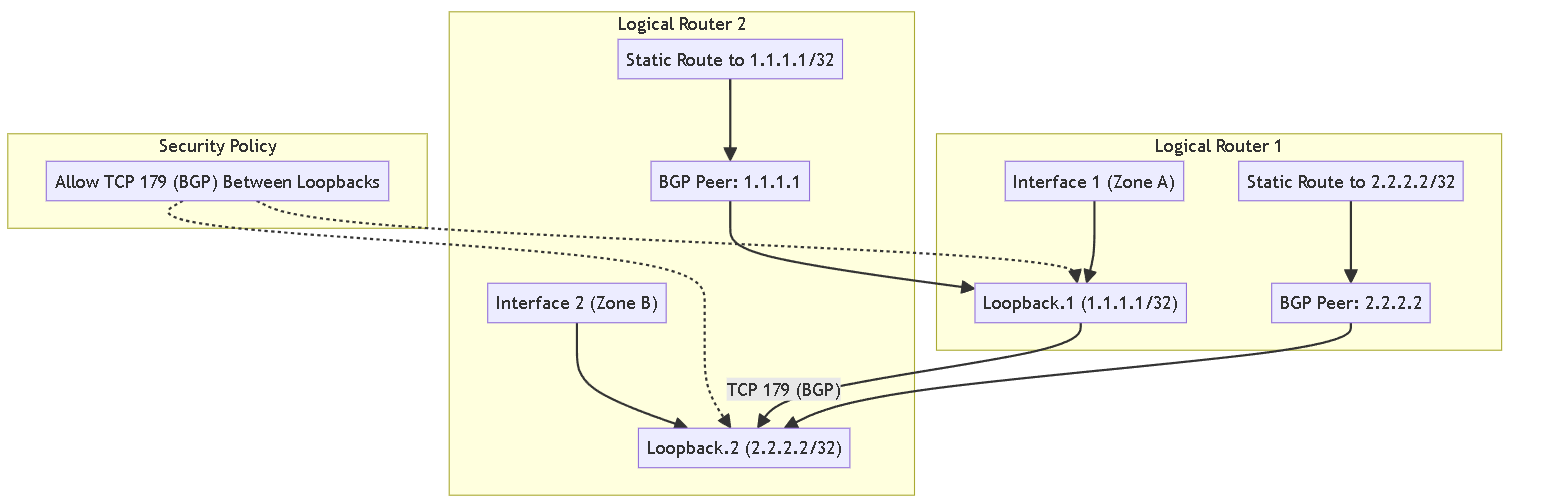
The firewall supports **only one hop between logical routers**. A route cannot go from A to B to C; it must go directly from A to C.
If dynamically routing between 3 or more LRs this way, a **full mesh** of iBGP peerings between loopbacks is usually needed due to the one-hop rule. BGP is generally more suited for this than OSPF.
Advanced Routing Engine (ARE) Context
Logical Routers are part of the newer **Advanced Routing Engine (ARE)** (PAN-OS 10.2+), replacing **legacy Virtual Routers (VRs)**.
ARE offers improved reliability, simpler configuration via reusable **profiles**, and better troubleshooting with packet captures per protocol/LR.
ARE does **not automatically create a default logical router**.
The concept is similar to **VRF** (Cisco) or **VDOMs** (Fortinet) for routing segmentation.
Other Considerations
The **management interface** has its own separate routing table.
**Service Routes** can direct specific management traffic through an LR interface.
NAT policy lookup happens **before** the second route lookup for Destination NAT.
Configure a Logical Router
In order to perform network routing, the Advanced Routing Engine requires you to configure at least one logical router ; there is no default logical router. A logical router maintains a separate routing information base and keeps routes from exposure to other logical routers. The number of logical routers supported for an Advanced Routing Engine varies based on firewall model.
Before you can configure a logical router, you must Enable Advanced Routing .
- Select Network > Routing > Logical Routers and Add a logical router by Name (maximum of 31 characters). The name must start with an alphanumeric character, underscore (_), or hyphen (-), and can contain a combination of alphanumeric characters, underscore (_) or hyphen(-). No dot (.) or space is allowed.
-
Add interfaces to the logical router.
- While still on the Logical Router General tab, select the Interface tab.
- Add an interface to the logical router by selecting from the list of interfaces. An interface can belong to only one logical router. Repeat to add more interfaces, as in the following example for the logical router named LR-1:
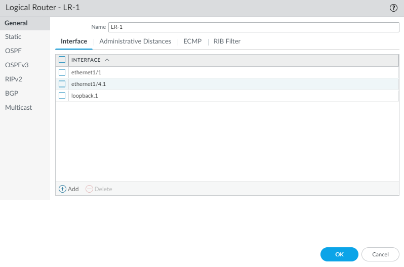
Assigning Interfaces to a Logical Router. -
(Optional) Select
Administrative Distances
to change the global administrative distance (from the default setting) for various types of routes.
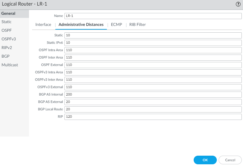
Configuring Administrative Distances per Logical Router. - Static —Range is 1 to 255; default is 10.
- Static IPv6 —Range is 1 to 255; default is 10.
- OSPF Intra Area —Range is 1 to 255; default is 110.
- OSPF Inter Area —Range is 1 to 255; default is 110.
- OSPF External —Range is 1 to 255; default is 110.
- OSPFv3 Intra Area —Range is 1 to 255; default is 110.
- OSPFv3 Inter Area —Range is 1 to 255; default is 110.
- OSPFv3 External —Range is 1 to 255; default is 110.
- BGP AS Internal —Range is 1 to 255; default is 200.
- BGP AS External —Range is 1 to 255; default is 20.
- BGP Local Route —Range is 1 to 255; default is 20.
- RIP —Range is 1 to 255; default is 120.
- Click OK .
-
(
On a firewall supporting multiple virtual systems
) Assign the logical routers to a virtual system.
- Select Device > Virtual Systems and select a virtual system and General .
- Add one or more Logical Routers .
- Click OK .
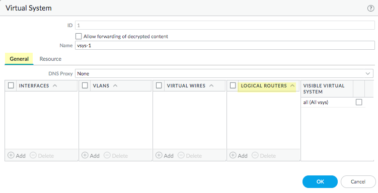
Assigning Logical Routers to a Virtual System. - Click OK .
-
(Optional) Configure ECMP for a logical router by navigating to
Network > Routing > Logical Routers
, selecting a logical router, and then
General > ECMP
. Configure ECMP for a logical router much as you would for a virtual router on a legacy routing engine.
ECMP is not supported for equal-cost routes where one or more of those routes has a virtual router or logical router as the next hop. None of the equal-cost routes will be installed in the Forwarding Information Base (FIB).
- Commit the changes.
- ( For a firewall with a pre-existing configuration ) Select Device > Setup > Operations and Reboot Device . Then log back into the firewall.
-
(Optional) View Runtime Stats for a logical router.
- Select Network > Routing > Logical Routers and for a specific logical router, select More Runtime Stats on the far right.
- To see the route tables for all protocols, on the Routing tab, select Route Table and Display Address Family : IPv4 and IPv6 , IPv4 Only , or IPv6 Only .
- To see entries in the Forwarding Information Base (FIB), select Forwarding Table .
- Select Static Route Monitoring to see the static routes you are monitoring.
- Select the BGP tab and then Summary to see BGP settings.
- Select Peer to see BGP peer settings.
- Select Peer Group to see BGP peer group settings.
- Select Route and Display Address Family : IPv4 and IPv6 , IPv4 Only , or IPv6 Only to see the attributes of BGP routes.
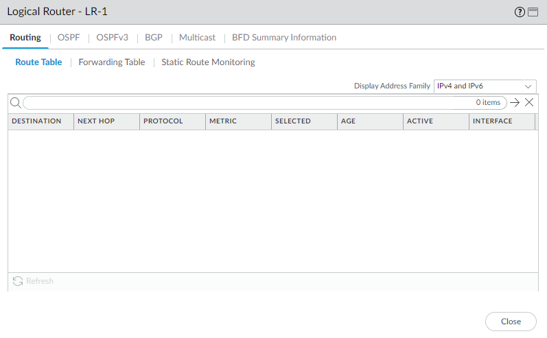
Viewing Runtime Stats - Route Table. - Access the CLI to view advanced routing information. The PAN-OS CLI Quick Start lists the commands in the CLI Cheat Sheet: Networking . Use commands like show advanced-routing logical-router <lr-name> routing-table .
Create a Static Route
Create a static route for a logical router in an Advanced Routing Engine .
- Configure a Logical Router .
-
Create a static route.
- Select Network > Routing > Logical Routers and select the logical router.
- Select Static and Add an IPv4 or IPv6 static route by Name (maximum of 63 characters). The name must start with an alphanumeric character, underscore (_), or hyphen (-), and can contain a combination of alphanumeric characters, underscore, or hyphen. No dot (.) or space is allowed.
-
For
Destination
, enter the route and netmask (for example,
192.168.2.0/24for an IPv4 address or2001:db8:123:1::0/64for an IPv6 address). If you’re creating a default route, enter the default route (0.0.0.0/0for an IPv4 address or::/0for an IPv6 address). Alternatively, you can select or create an address object of type IP Netmask. - For Interface , specify the outgoing interface for packets to use to go to the next hop. Specifying an interface provides stricter control over which interface the firewall uses rather than using the interface in the route table for the next hop of this static route.
-
For
Next Hop
, select one of the following:
- IP Address or IPv6 Address —Enter the IP address (for example, 192.168.56.1 or 2001:db8:49e:1::1) when you want to route to a specific next hop. You must Enable IPv6 on the interface to use an IPv6 next hop address. If you’re creating a default route, for Next Hop you must select IP Address and enter the IP address for your internet gateway. Alternatively, you can create an address object of type IP Netmask (must have /32 or /128 mask).
- Next LR —Select to make the next logical router (in the list of logical routers) the next hop.
- FQDN —Enter a Fully Qualified Domain Name.
- Discard —Select to drop packets that are addressed to this destination.
- None —Select if there is no next hop for the route (e.g., point-to-point connection).
- Enter the Admin Dist for the static route (range is 10 to 240; default is 10). This value overrides the global static administrative distance specified for the logical router.
- Enter a Metric for the static route (range is 1 to 65,535; default is 10).
- (Optional) If you want to use BFD, select a BFD Profile you created, or select the default profile, or create a BFD profile to apply to the static route; default is None (Disable BFD) .
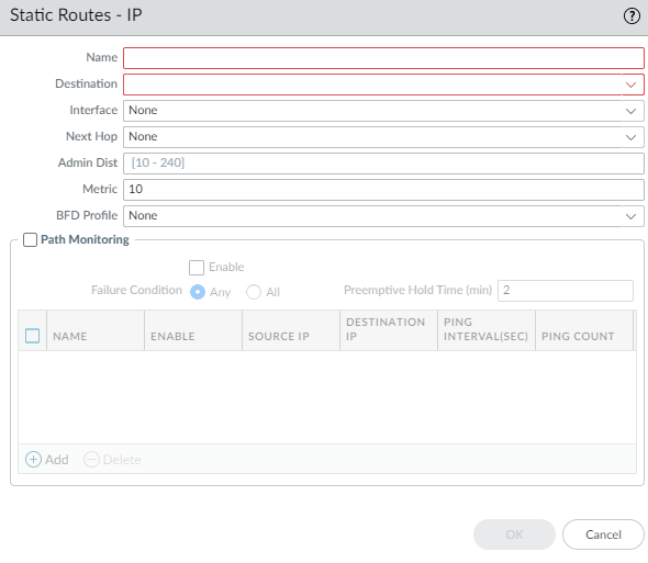
Configuring a Static Route - General Options. -
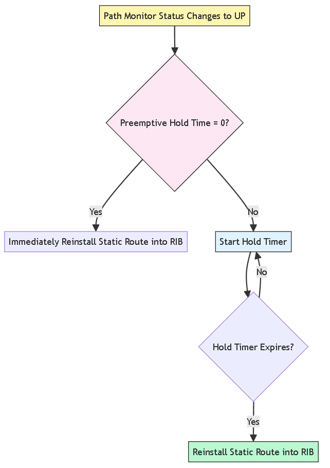
(Optional) Configure path monitoring for the static route; you can monitor up to 128 static routes.
- Select Path Monitoring tab to allow configuration of path monitoring (default is disabled).
- Enable path monitoring (default is disabled).
-
Failure Condition
determines whether path monitoring for the static route is based on one (any) or all monitored destinations. Select whether
Any
or
All
of the monitored destinations for the static route must be unreachable by ICMP for the firewall to remove the static route from the RIB and FIB and add the static route that has the next lowest metric (going to the same destination) to the FIB.
Select All to avoid the possibility of any single monitored destination signaling a route failure when the destination is simply offline for maintenance. -
(Optional) Specify the
Preemptive Hold Time (min)
, the number of minutes a downed path monitor must remain in Up state before the firewall reinstalls the static route into the RIB; range is 0 to 1,440; default is 2. A setting of 0 (zero) causes the firewall to reinstall the route into the RIB immediately upon the path monitor coming up.
If a link goes down or flaps during the hold time, when the link comes back up, the path monitor resumes and the Preemptive Hold Time is reset. -
Add
a path monitoring destination by
Name
.
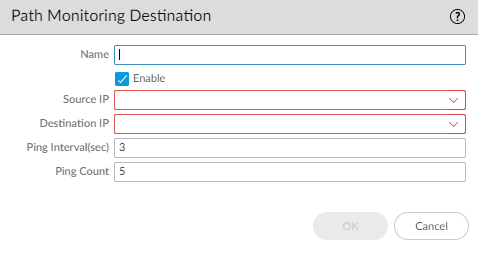
Adding a Path Monitoring Destination. - Enable the path monitoring destination.
- For Source IP , select the IP address that the firewall uses in the ICMP ping to the monitored destination (select specific IP if interface has multiple, or DHCP Client address).
-
For
Destination IP
, enter an IP address or address object to which the firewall will monitor the path. The monitored destination and static route destination must use the same address family (IPv4 or IPv6).
The destination IP address should belong to a reliable endpoint. - (Optional) Specify the ICMP Ping Interval (sec) (range is 1 to 60; default is 3).
- (Optional) Specify the ICMP Ping Count of packets that don’t return before considering the route down (range is 3 to 10; default is 5).
- Click OK to save the path monitor destination.
- Click OK twice to save the static route.
-
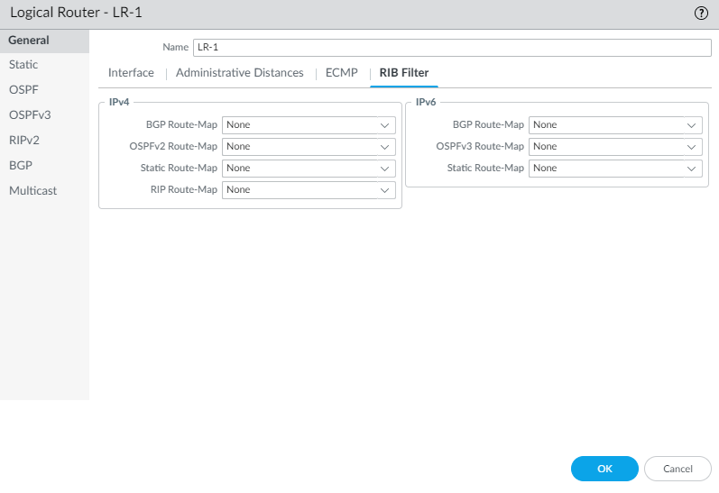
(Optional) Control the static routes that are placed in the global RIB using a RIB Filter.
You might configure static routes and redistribute them, but not want them in the protocol’s local route table or global RIB. You might want to add only specific static routes to the global RIB.
- Select Network > Routing > Logical Routers and select a logical router.
- Select RIB Filter .
- To filter IPv4 static routes and connected routes, for Static Route-Map , select a Redistribution Route Map or create a new one .
- To filter IPv6 static routes and connected routes, for Static Route-Map (under IPv6), select a Redistribution Route Map or create a new one .
- Click OK .

Configuring RIB Filters for a Logical Router. - (Optional) Change the default administrative distances for static IPv4 and static IPv6 routes within a logical router .
- Commit the changes.
- Access the CLI to view the static route path monitor: show advanced-routing static-route-path-monitor . See the CLI Cheat Sheet: Networking for more commands.
Configure BGP on an Advanced Routing Engine
Perform the following task to configure BGP for a logical router on an Advanced Routing Engine .
Before you configure BGP, consider the many useful routing profiles and filters that you can apply to BGP peer groups, peers, redistribution rules, and aggregate route policies, and thereby save configuration time and maintain consistency. You can create profiles and filters in advance or as you progress through configuring BGP.
- Configure a Logical Router .
-
Enable BGP and configure general BGP settings.
- Select Network > Routing > Logical Routers and select a logical router.
- Select BGP > General and Enable BGP for this logical router.
- Assign a Router ID to BGP for the logical router, which is typically an IPv4 address to ensure the Router ID is unique.
- Assign the Local AS , which is the number of the AS to which the logical router belongs; range is 1 to 4,294,967,295.
- If you want to apply BFD to BGP, for Global BFD Profile select a BFD profile you created, or select the default profile, or create a new BFD profile ; default is None (Disable BFD) .
- Select Install Route to install learned BGP routes into the global routing table; default is disabled.
- Select Fast Failover to have BGP terminate a session with an adjacent peer if the link to that peer goes down, without waiting for the Hold Time to expire; default is enabled.
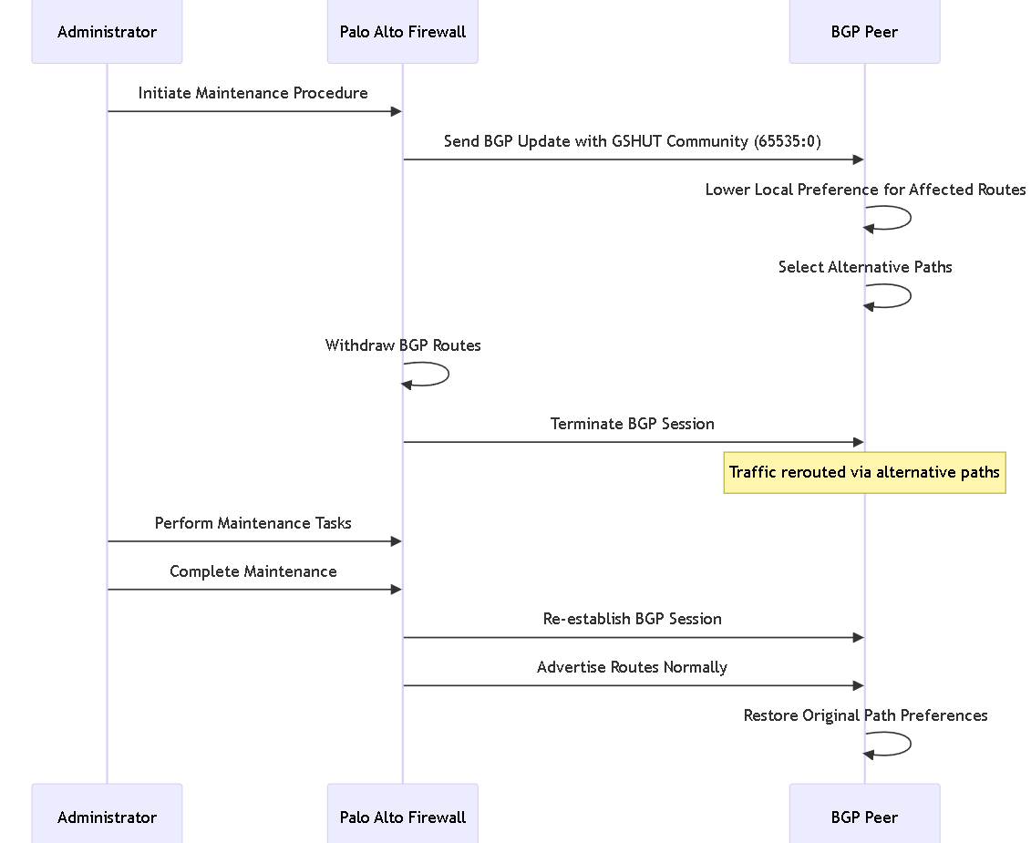
- Select Graceful Shutdown to have BGP lower the preference of eBGP peering links during a maintenance operation so that BGP can choose and propagate alternative paths, based on RFC 8326 ; default is disabled.
- Select ECMP Multiple AS Support if you configured ECMP and you want to run ECMP over multiple BGP autonomous systems; default is disabled.
- Enforce First AS to cause the firewall to drop an incoming Update packet from an eBGP peer that does not list the eBGP peer’s own AS number as the first AS number in the AS_PATH attribute; default is enabled.
- Specify the Default Local Preference that can be used to determine preferences among different paths; range is 0 to 4,294,967,295; default is 100.
-
Enable
Graceful Restart and configure the following timers:
- Stale Route Time (sec) —Specifies the length of time, in seconds, that a route can stay in the stale state (range is 1 to 3,600; default is 120).
- Max Peer Restart Time (sec) —Specifies the maximum length of time, in seconds, that the local device accepts as a grace period restart time for peer devices (range is 1 to 3,600; default is 120).
- Local Restart Time —Specifies the length of time, in seconds, that the local device waits to restart. This value is advertised to peers (range is 1 to 3,600; default is 120).
-
For
Path Selection
:
- Always Compare MED —Enable this comparison to choose paths from neighbors in different autonomous systems; default is disabled.
- Deterministic MED Comparison —Enable this comparison to choose between routes that are advertised by IBGP peers (BGP peers in the same autonomous system); default is enabled.
- Click OK .
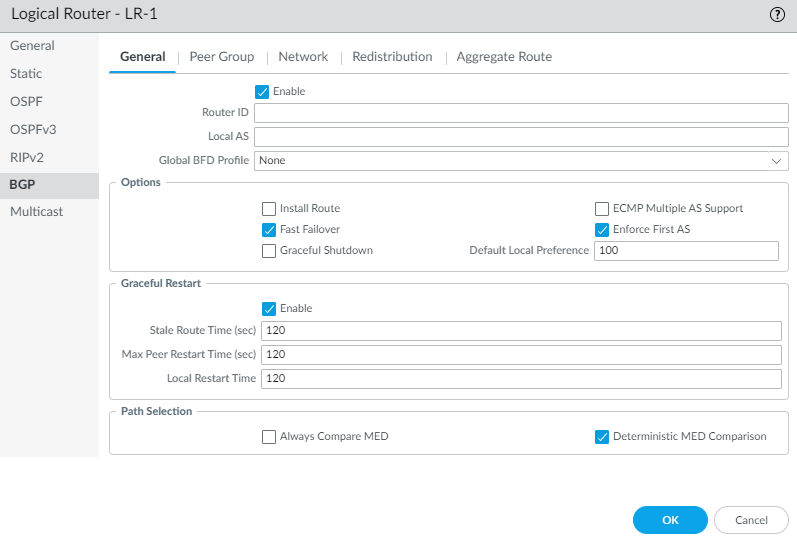
Enabling BGP and General Settings. 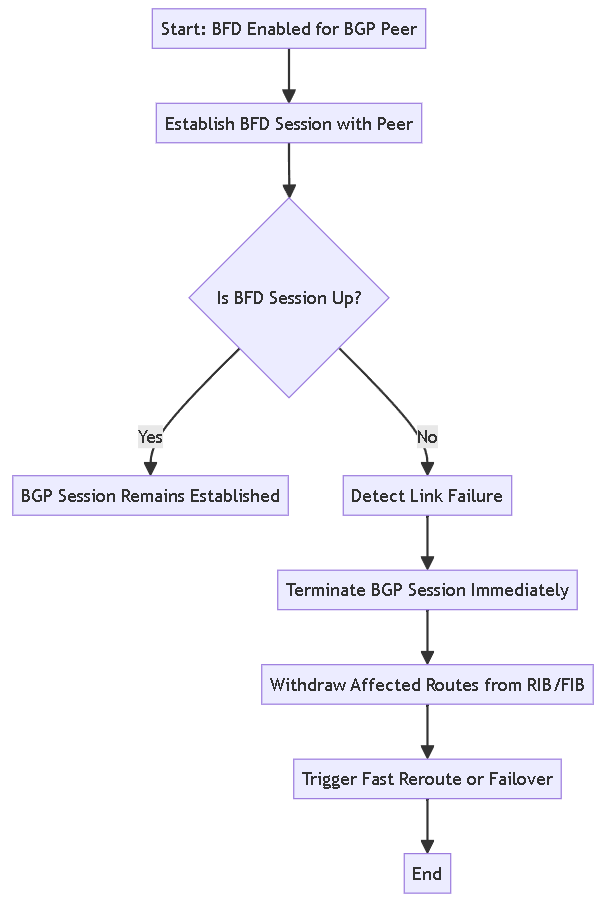
-
Configure a BGP peer group.
- Select BGP > Peer Group and Add a BGP peer group by Name (maximum of 63 characters). The name must start with an alphanumeric character, underscore (_), hyphen (-), or dot (.) and can contain alphanumeric characters, underscores, hyphens and dots. A space is not allowed. The name must be unique within the logical router and across all logical routers.
- Enable the peer group.
- Select the Type of peer group: IBGP or EBGP .
- To specify many IPv4 Address Family options for the peer group, select an AFI Profile that you created, select the default profile, or create a new BGP Address Family profile ; the default is None .
- To specify many IPv6 Address Family options for the peer group, select an AFI Profile that you created, select the default profile, or create a new BGP Address Family profile ; the default is None .
-
To apply
IPv4 Filtering Profile
options to the peer group, select a
BGP Filtering Profile
that you created or
create a new BGP Filtering profile
; the default is
None
.
A BGP Filtering Profile describes how to configure many BGP options for IPv4, such as import or export BGP routes, accept or prevent routes being added to the local BGP RIB, conditionally advertise routes, and unsuppress dampened or summarized routes. -
To apply
IPv6 Filtering Profile
options to the peer group, select a
BGP Filtering Profile
that you created or
create a new BGP Filtering profile
; the default is
None
.
A BGP Filtering Profile describes how to configure many BGP options for IPv6. - For Connection Options, select an Auth Profile or create a new BGP Authentication profile to control MD5 authentication between BGP peers in the peer group. Default is None .
- Select a Timer Profile or create a new BGP Timer Profile to control various BGP timers that affect keepalive and update messages that advertise routes. Default is None .
- Set Multi Hop —the time-to-live (TTL) value in the IP header (range is 0 to 255; default is 0). The default value of 0 means 1 for eBGP. The default value of 0 means 255 for iBGP.
- Select a Dampening Profile or create a new Dampening Profile to determine how to penalize a flapping route to suppress it from being used until it stabilizes. Default is None .
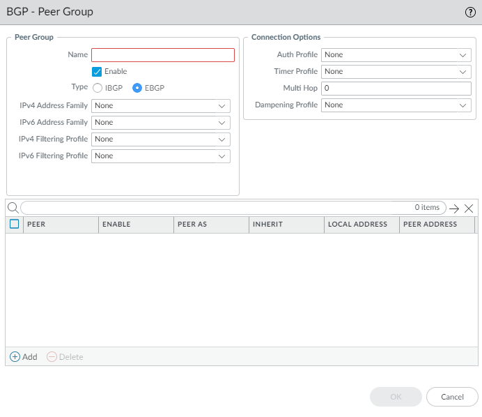
Configuring a BGP Peer Group - General. -
Add a BGP peer to the peer group.
- Add a peer by Name (max 63 chars, unique, alphanumeric, _, -, .).
- Enable the peer (default).
- Select Passive to prevent the peer from initiating a session with its neighbors (default disabled).
- Enter the Peer AS to which the peer belongs (1 to 4,294,967,295).
- Select Addressing tab. Choose whether the peer will Inherit IPv4/IPv6 AFI and filtering profiles from the peer group (Yes/No, default Yes).
-
If inheriting (Yes):
- For Local Address , select the Interface and specific IP Address if multiple exist.
- For Peer Address , select IP (and enter/select IP/Address Object) or FQDN (and enter FQDN/FQDN Address Object).
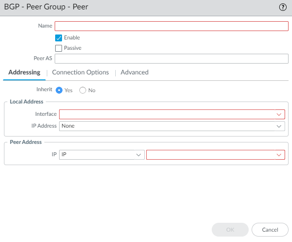
BGP Peer Addressing (Inherit Yes). -
If not inheriting (No):
- Specify IPv4 Address Family options (AFI Profile: select existing, default, inherit, create new, or none). The AFI Profile allows you to specify Route Reflector client status.
- Specify IPv6 Address Family options (AFI Profile: select existing, inherit, create new, or none).
- Specify IPv4 Filtering Profile options (Filtering Profile: select existing, inherit, create new, or none).
- Specify IPv6 Filtering Profile options (Filtering Profile: select existing, inherit, create new, or none).
- Configure Local Address (Interface/IP) and Peer Address (IP/FQDN) as above.
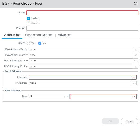
BGP Peer Addressing (Inherit No). A peer group/peer can have both IPv4 and IPv6 profiles. If both are applied to the group, peers default to Inherit No. Peering interface must have both IPv4 and IPv6 addresses. You can selectively inherit/override profiles per peer.
- Select Connection Options tab to override peer group settings for this peer.
- Select Auth Profile (select existing, inherit (default), create new, or None).
- Select Timer Profile (select existing, inherit (default), create new, default, or None).
- Set Multi Hop (0-255, default inherit).
- Select Dampening Profile (select existing, inherit (default), create new, or None).
- Select Advanced tab.
- Enable Sender Side Loop Detection (default disabled). Checks AS_PATH before sending updates to prevent loops.
- Apply a peer-specific BFD Profile (select existing, default, inherit-lr-global-setting (default), None (disable BFD), or create new). Overrides BGP global BFD setting if not None.
- Click OK to save the peer.
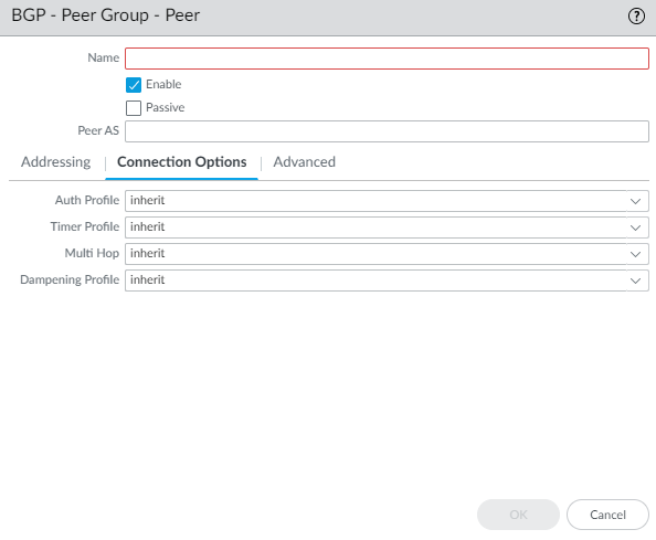
BGP Peer Connection Options. 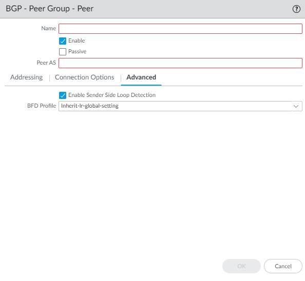
BGP Peer Advanced Options. 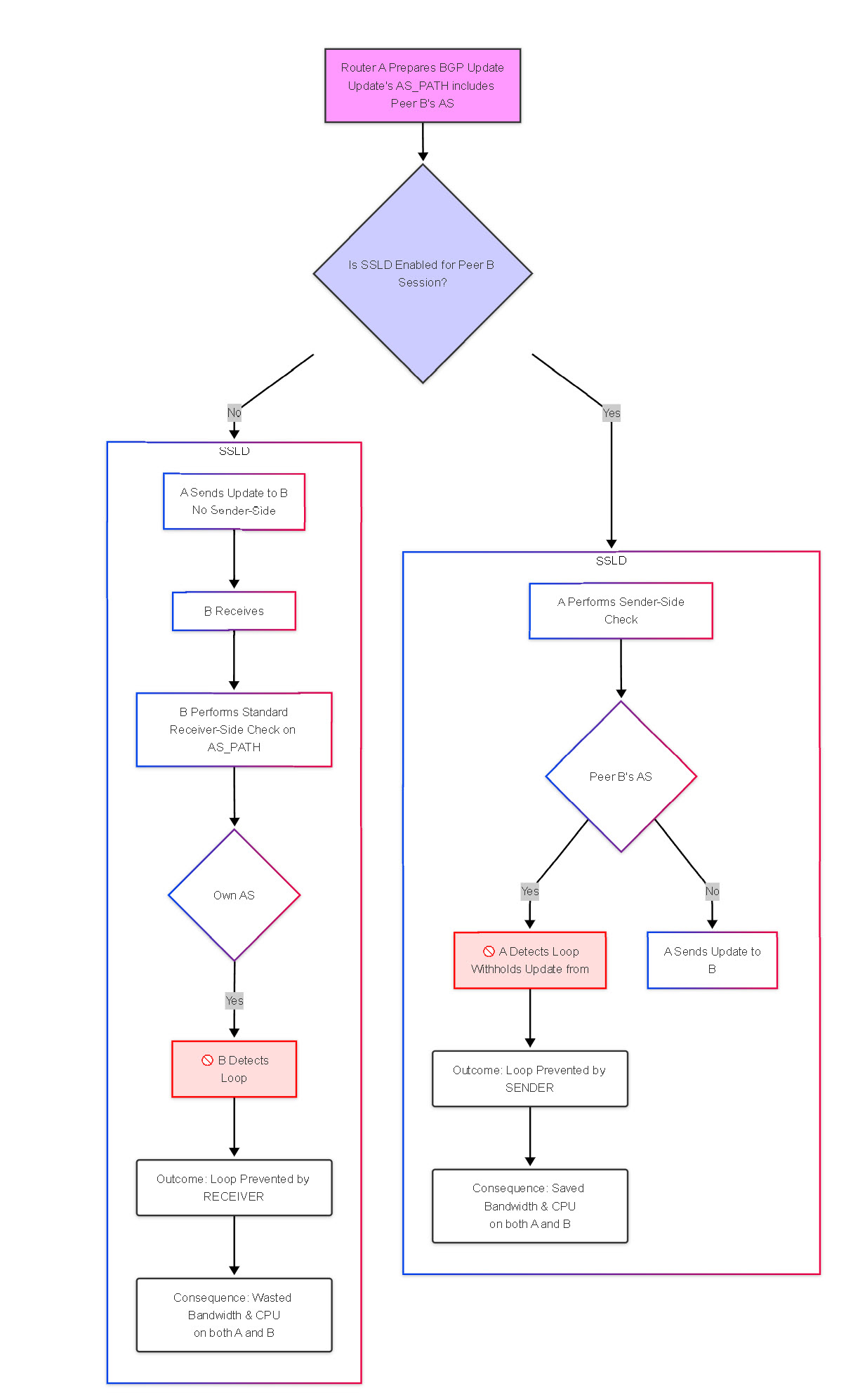
-
Specify network prefixes to advertise to neighbors. (Helpful after network changes).
- Select BGP > Network tab.
- Always Advertise Network Route (default enabled). Advertise configured network routes even if not reachable locally. Uncheck to only advertise if resolved in local route table.
- Select IPv4 or IPv6 tab.
- Add a Network prefix to advertise (e.g., 10.1.1.0/24).
- Select Unicast to advertise in Unicast AFI (default enabled).
- (IPv4 only) Select Multicast to advertise in Multicast AFI (default disabled).
- (IPv4 only) Select Backdoor to increase AD for this prefix internally, keeping it within the AS but making it less preferred than IGP routes (default disabled).
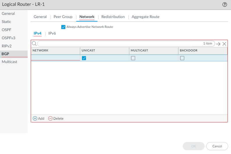
Configuring BGP Network Advertisements. -
Redistribute static, connected, OSPF, OSPFv3, or RIPv2 routes into BGP using a Redistribution Profile.
- Select BGP > Redistribution tab.
- To redistribute IPv4 routes, for IPv4 Redistribution Profile -- Unicast , select a BGP Redistribution profile or create a new one (default None).
- To redistribute IPv6 routes, for IPv6 Redistribution Profile -- Unicast , select a BGP Redistribution profile or create a new one (default None).
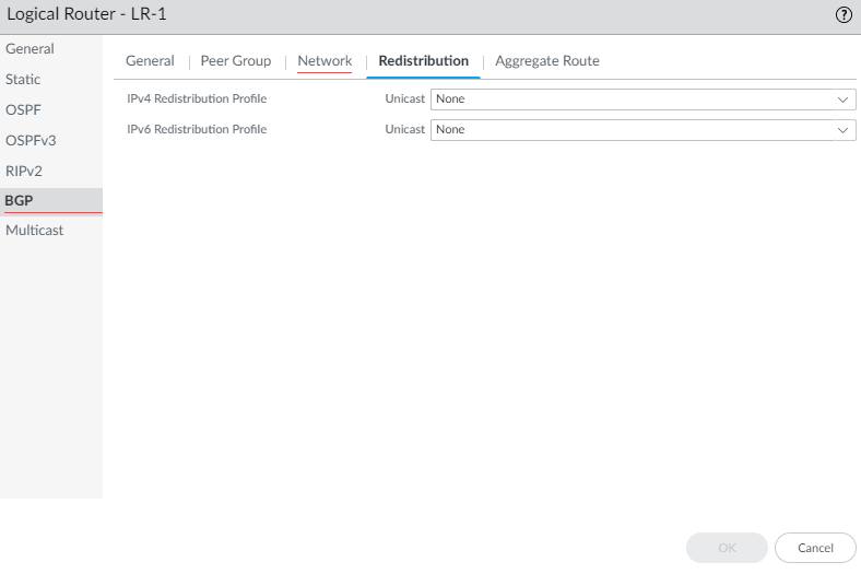
Configuring BGP Redistribution. -
(Optional) Create an aggregate route policy to summarize routes.
- Select BGP > Aggregate Route and Add a policy by Name (max 63 chars, unique, alphanumeric, _, -, .).
- Enter a helpful Description .
- Enable the policy.
- Select Summary Only to advertise only the summary prefix (default disabled). Mutually exclusive with Suppress Map. Use an Unsuppress Map in a Filtering Profile to advertise specific routes when Summary Only is enabled.
- Select AS Set to advertise the prefix with the list of AS numbers that make up the aggregate (default disabled).
- Select Aggregate Same MED Only to only aggregate routes with the same MED value (default enabled).
- Select the Type : IPv4 or IPv6 .
- Enter the Summary Prefix (IP/Netmask or Address Object).
- To prevent specific routes from being aggregated, select a Suppress Map route map or create a new one matching the routes to suppress. The route map must *permit* the routes you want to suppress from aggregation. (Default None). Mutually exclusive with Summary Only.
- To set attributes for the summary prefix, select an Attribute Map route map or create a new one (Default None).
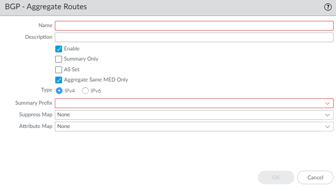
Configuring a BGP Aggregate Route Policy. - Click OK to save the logical router BGP config.
-
(Optional) Control BGP routes that are placed in the global RIB using a RIB Filter.
- Select RIB Filter tab.
- To filter IPv4 BGP routes, in the IPv4 area, for BGP Route-Map , select a Redistribution Route Map or create a new one .
- To filter IPv6 BGP routes, in the IPv6 area, for BGP Route-Map , select a Redistribution Route Map or create a new one .
- Click OK .
Configuring RIB Filters for a Logical Router.
Create BGP Routing Profiles
On an Advanced Routing Engine ( The newer routing software within PAN-OS, replacing the legacy engine and offering features like profiles and enhanced stability ), BGP ( Border Gateway Protocol, the core routing protocol of the Internet, used to exchange reachability information between different Autonomous Systems ) has many settings that you can easily configure in a profile ( a reusable template containing specific configuration settings ) and then apply to a BGP peer group ( a collection of BGP neighbors, or peers, that share the same outbound policies ) or peer ( an individual neighboring BGP router ) or to redistribution rules ( rules defining how routes learned from one routing protocol, like OSPF or static, are advertised into BGP ). Reuse profiles to apply them to multiple logical routers ( PAN-OS term for independent routing instances, similar to VRFs in Cisco ) and virtual systems ( PAN-OS feature allowing a single firewall to be partitioned into multiple independent logical firewalls ). Create multiple profiles of the same type to handle different peer groups and peers differently. BGP peer groups and peers inherit ( automatically receive settings from a higher level, like a global setting or a group setting ) global profiles; you can also create a profile for a BGP peer group to override the global profile, and create a profile for a BGP peer, which overrides the profile for the peer group to which the peer belongs.
This topic describes the BGP routing profiles and how to create them.
- BGP Authentication Profiles —Specify the Secret key ( a password or pre-shared key ) for MD5 authentication ( a method using the MD5 hash algorithm and a shared secret key to verify the identity of BGP peers and ensure message integrity ). Reference in a peer group or peer configuration.
- BGP Timer Profiles — Control keepalive ( small BGP messages sent periodically to verify a neighbor is still up ), hold time ( the maximum duration a router will wait for a keepalive from a neighbor before declaring it down ), reconnect ( time interval between attempts to re-establish a failed BGP session ), open delay ( a pause before sending the initial BGP OPEN message, allowing routing to stabilize ), and route advertisement intervals ( minimum time enforced between sending updates for the same prefix to prevent excessive flapping ). Reference in a peer group or peer configuration.
- BGP Address Family Profiles —Determine IPv4/IPv6 behavior using AFI/SAFI ( Address Family Identifier, e.g., IPv4/IPv6, and Subsequent Address Family Identifier, e.g., Unicast/Multicast, which define the type of network information BGP carries ), route reflector ( a BGP role that reflects iBGP routes to other iBGP peers, avoiding full-mesh requirement ) status, default route origination ( advertising a default route, 0.0.0.0/0 or ::/0, into BGP ), AS path handling ( rules for processing the AS_PATH attribute, which lists ASes a route has traversed ), prefix limits ( setting a maximum number of routes accepted from a peer ), next-hop behavior ( rules for setting the next-hop IP address in BGP updates, like 'next-hop-self' ), community handling ( processing special tags called communities attached to routes for policy purposes ), and ORF ( Outbound Route Filtering, allowing a peer to request specific route filters from its neighbor ). Reference in a peer group or peer configuration.
- BGP Dampening Profiles —Determine how to penalize and suppress flapping routes ( routes that repeatedly become available and unavailable ) to improve network stability. Reference in a peer group or peer configuration.
- BGP Redistribution Profiles —Redistribute static ( manually configured ), connected ( directly attached networks ), OSPF ( Open Shortest Path First, a common interior gateway protocol - v2 for IPv4, v3 for IPv6 ), or RIP ( Routing Information Protocol, an older interior gateway protocol - v2 used here ) routes into BGP using route maps ( policy tools to filter routes and modify attributes during redistribution ). Reference on Network > Routing > Logical Routers > BGP > Redistribution .
- BGP Filtering Profiles —Apply multiple filters like AS Path ( filtering based on the list of Autonomous Systems traversed ), Distribute List ( filtering using standard Access Control Lists based on prefix address ), Prefix List ( filtering based on prefix address and prefix length ), Route Map ( complex policy tool for matching routes and setting attributes ) for inbound/outbound route control, conditional advertisement ( advertising some routes only if other routes exist or don't exist ), and unsuppressing routes ( forcing advertisement of routes normally suppressed by dampening or aggregation ). Reference in a peer group or peer configuration.
-
Create a BGP Authentication profile.
- Select Network > Routing > Routing Profiles > BGP .
- Add a BGP Auth Profile by Name (max 63 chars, unique, alphanumeric, _, -, .).
- Enter the Secret ( The shared password for MD5 authentication ) and Confirm Secret . Used for MD5 authentication. Allowed chars: !@#%^_- and alphanumeric.
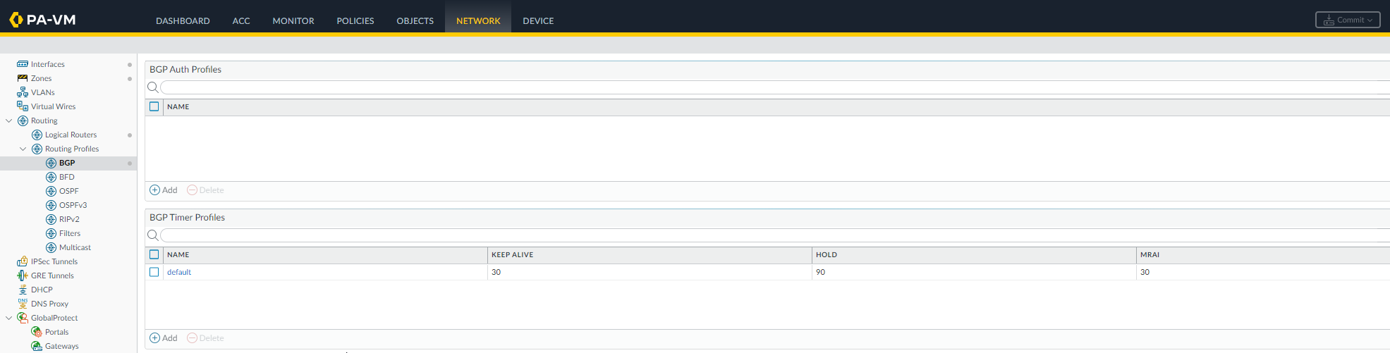
BGP Routing Profiles Section. -
Create a BGP Timer profile.
- Select Network > Routing > Routing Profiles > BGP .
- Select the default BGP Timer Profile to view defaults.
- If needed, Add a BGP Timer Profile by Name (max 63 chars, unique, alphanumeric, _, -, .).
- Set Keep Alive Interval (sec) ( Time in seconds between sending keepalive messages to a peer; 0 disables keepalives ) (0-1200, default 30).
- Set Hold Time (sec) ( Time in seconds a router waits for a keepalive before declaring the peer down; must be >= 3 seconds ) (3-3600, default 90). Often 3x Keep Alive.
- Set Reconnect Retry Interval ( Time in seconds to wait before trying to reconnect to a peer after the session drops ) (1-3600, default 15).
- Set Open Delay Time (sec) ( Time in seconds to wait after TCP connection establishment before sending the BGP OPEN message ) (0-240, default 0).
- Set Minimum Route Advertise Interval (sec) ( Minimum time in seconds between sending UPDATE messages for the same network prefix to a peer ) (1-600, default 30).
- Click OK .
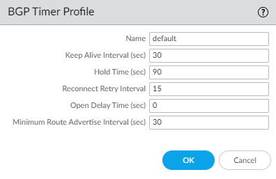
Default BGP Timer Profile. -
To use
MP-BGP
(
Multi-Protocol BGP, allowing BGP to carry routes for different protocols like IPv6 or VPNs
), create a BGP Address Family Identifier (AFI) profile.
- Select Network > Routing > Routing Profiles > BGP .
- Add a BGP Address Family Profile by Name (max 63 chars, unique, alphanumeric, _, -, .).
- Select IPv4 or IPv6 AFI ( Address Family Identifier: specifies the main network protocol, IPv4 or IPv6 ).
- Select unicast ( standard one-to-one communication routes ) or multicast ( one-to-many communication routes ) SAFI ( Subsequent Address Family Identifier: specifies the type of route within the AFI ) (Multicast only for IPv4).
- On the appropriate tab (unicast/multicast), Enable SAFI ( Activate BGP negotiation for this specific address type ) (at least one must be enabled).
- Soft reconfiguration... : ( Enable inbound soft reconfiguration, allowing policy changes without resetting the BGP session by storing received routes ) Perform soft reset on peer updates (enabled by default).
- Advertise all paths to peers : ( If BGP multipath is enabled, send all available equal-cost paths to peers instead of just the best path ) Send all paths for multipath preservation.
- Advertise the bestpath for each neighboring AS : ( Standard behavior: send only the single best path selected by BGP ) Send only best paths (disable to send same path to all, potentially useful in specific reflection scenarios).
- Override ASNs... : ( Replace occurrences of the local AS number in the AS_PATH when advertising routes back into the same AS, typically used in specific scenarios like AS migration or complex iBGP designs ) Replace local AS in AS_PATH if sending to peer in same AS but through intermediate AS.
- Enable Route Reflector Client ( Configure this firewall to act as a route reflector for the specified peer, meaning it will re-advertise routes learned from this client to other iBGP peers ) if this peer acts as one.
- Originate Default Route : ( Instruct the firewall to generate and advertise a default route (0.0.0.0/0 or ::/0) to this peer/group ) Generate a default route locally.
- Default Originate Route-Map : ( Apply a route map to set specific attributes (like community, metric) or conditionally originate the default route ) Select/create route map to control default route attributes.
- Allow AS in : ( Control whether routes are accepted if they contain the firewall's own AS number in the AS_PATH. Standard BGP rejects these to prevent loops. 'Origin' allows accepting routes originated locally; 'Occurrence' allows a specific number of local AS appearances ) Control acceptance if own AS is in AS_PATH (Origin=accept, Occurrence=count, None=default).
- Number Prefixes : ( Maximum number of route prefixes allowed to be received from this peer/group ) Max prefixes accepted from peer (1-4,294,967,295, default 1000).
- Threshold : ( Percentage of the 'Number Prefixes' limit at which to trigger the configured action ) Percentage of Max Prefixes before action (1-100, default 100).
- Action : ( What to do when the prefix limit threshold is reached: log a warning or tear down and restart the BGP session ) Warning Only or Restart connection if prefix limit exceeded.
- Select Next Hop behavior: ( How to set the next-hop attribute for routes advertised to iBGP peers ) Self ( change next hop to the advertising router's IP - standard for iBGP ), Self Force ( force next-hop-self even for reflected routes ), None ( default, keep the original next hop learned from eBGP peer - generally requires IGP reachability to that next hop ).
- Remove Private AS : ( Control whether private AS numbers (64512-65534, etc.) are removed from the AS_PATH when advertising routes to eBGP peers ) All ( remove all private ASNs ), Replace AS ( replace private ASNs with the local AS number ), or None ( default, leave private ASNs in the path ).
- Send Community : ( Choose which types of BGP community attributes (Standard, Extended, Large) to include in updates sent to this peer/group ) Choose which community types to send (All, Both, Extended, Large, Standard, None (default)).
- ORF List : ( Configure Outbound Route Filtering capability negotiation - allows the peer to send prefix lists to request specific routes ) Configure Outbound Route Filtering capability (none, both, receive, send).
- Click OK .
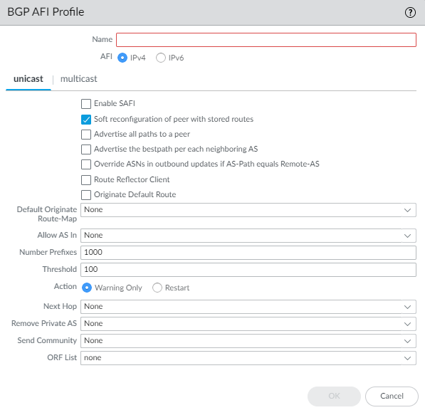
BGP Address Family (AFI) Profile. -
Create a BGP Dampening Profile. (
Defines parameters to penalize and temporarily suppress unstable routes
).
- Select Network > Routing > Routing Profiles > BGP .
- Add a BGP Dampening Profile by Name (max 63 chars, unique, alphanumeric, _, -, .).
- Enter a Description .
- Suppress Limit —( The penalty score threshold; if a route's penalty exceeds this, it's suppressed ) Cumulative penalty value to suppress route (1-20000, default 2000).
- Reuse Limit —( The penalty score threshold below which a suppressed route can be advertised again ) Threshold penalty value below which a route can be reused (1-20000, default 750).
- Half Life (min) —( The time (in minutes) it takes for a route's penalty score to decay by half when it's stable ) Time (minutes) for penalty to decay by half (1-45, default 15).
- Maximum Suppress Time (min) —( The absolute maximum time (in minutes) a route can remain suppressed, regardless of its penalty score ) Max time (minutes) a route can be suppressed (1-255, default 60).
- Click OK .
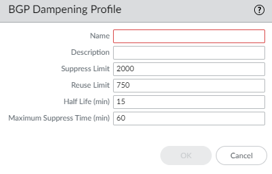
BGP Dampening Profile. -
Create a BGP Redistribution Profile. (
Defines rules for importing routes from other sources into BGP
).
- Select Network > Routing > Routing Profiles > BGP .
- Add a BGP Redistribution Profile by Name (max 63 chars, unique, alphanumeric, _, -, .).
- Select the AFI (Address Family Identifier): IPv4 or IPv6 .
- Select protocol tab(s) to redistribute ( Static , Connected , OSPFv2 (IPv4 only), RIPv2 (IPv4 only), OSPFv3 (IPv6 only)).
-
For each selected protocol:
- Enable redistribution for that protocol.
- Configure the Metric ( For BGP, this typically refers to the MED - Multi-Exit Discriminator attribute, used to influence path selection between different entry points into a neighboring AS ) applied to redistributed routes (1-65535 or 0-4,294,967,295 for BGP).
- Select a Route-Map ( Redistribution Route Map ) ( A policy to selectively permit/deny routes for redistribution and set attributes like MED, community, etc. ) to filter which routes are redistributed and set attributes (default None).
- Click OK .
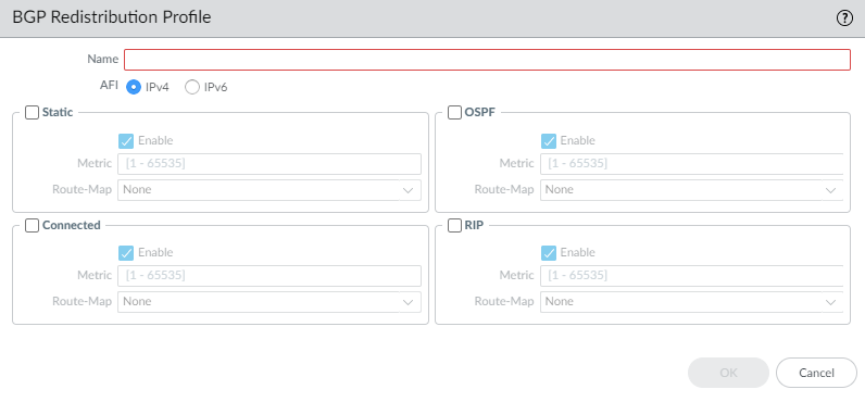
BGP Redistribution Profile. -
Create a BGP Filtering Profile. (
Defines various inbound and outbound filters applied to BGP updates
).
- Select Network > Routing > Routing Profiles > BGP .
- Add a BGP Filtering Profile by Name (max 63 chars, unique, alphanumeric, _, -, .).
- Enter a Description .
- Select IPv4 or IPv6 AFI.
- Select Unicast or Multicast SAFI.
-
Configure
Unicast
filters:
- Inbound Filter List : ( Filter received routes based on AS_PATH content using regular expressions defined in an AS Path Access List ) Select/create AS Path Access List to filter received routes by AS path.
- Network Filter > Inbound > Distribute List : ( Filter received routes using a standard Access Control List matching prefix addresses ) Select/create Access List to filter received routes by source/dest address. (Mutually exclusive with Prefix List).
- Network Filter > Inbound > Prefix List : ( Filter received routes using a specialized list matching prefix addresses and potentially prefix lengths ) Select/create Prefix List to filter received routes by prefix. (Mutually exclusive with Distribute List).
- Network Filter > Inbound Route Map : ( Apply complex BGP-specific policy (match/set actions) to received routes ) Select/create BGP Route Map for advanced filtering/attribute setting of received routes. (Applied with AND logic if List is also used).
- Outbound Filter List : ( Filter advertised routes based on AS_PATH content using regular expressions defined in an AS Path Access List ) Select/create AS Path Access List to filter advertised routes by AS path.
- Network Filter > Outbound > Distribute List : ( Filter advertised routes using a standard Access Control List matching prefix addresses ) Select/create Access List to filter advertised routes. (Mutually exclusive with Prefix List).
- Network Filter > Outbound > Prefix List : ( Filter advertised routes using a specialized list matching prefix addresses and potentially prefix lengths ) Select/create Prefix List to filter advertised routes. (Mutually exclusive with Distribute List).
- Network Filter > Outbound Route Map : ( Apply complex BGP-specific policy (match/set actions) to advertised routes ) Select/create BGP Route Map for advanced filtering/attribute setting of advertised routes. (Applied with AND logic if List is also used).
- Conditional Advertisement > Exist Map : ( A route map specifying routes that MUST exist in the BGP table for the advertisement to potentially occur ) Select Route Map. If matching routes exist in local RIB ( Routing Information Base - the main table holding routes learned by BGP before policy application )...
- Conditional Advertisement > Advertise Map : ( A route map specifying which routes should be advertised IF the condition set by the Exist/Non-Exist Map is met ) ...advertise routes matching this Route Map.
- Conditional Advertisement > Non-Exist Map : ( A route map specifying routes that MUST NOT exist in the BGP table for the advertisement to potentially occur ) Select Route Map. If matching routes DO NOT exist in local RIB...
- Conditional Advertisement > Advertise Map : ( A route map specifying which routes should be advertised IF the condition set by the Exist/Non-Exist Map is met ) ...advertise routes matching this Route Map.
- Unsuppress Map : ( A route map identifying specific routes that should be advertised even if they are currently suppressed by route dampening or because an aggregate route using 'summary-only' is active ) Select Route Map matching dampened/summarized routes you want to force advertise.
- (IPv4 AFI only) Configure Multicast filters similarly, or select Inherit from Unicast ( Apply the same filter settings defined for Unicast to Multicast routes ).
- Click OK .
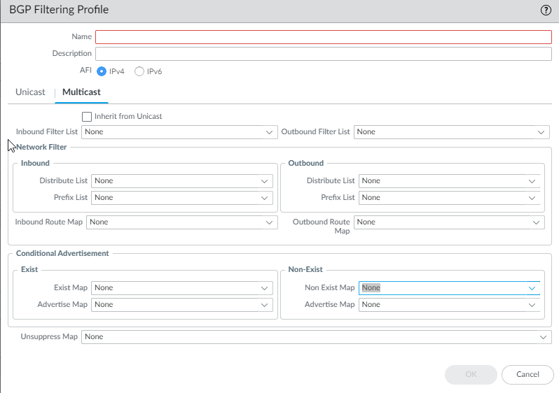
BGP Filtering Profile.
Create Filters for the Advanced Routing Engine
The Advanced Routing Engine supports various filters to control route propagation and attributes. Access lists, prefix lists, and redistribution route maps apply broadly, while AS path lists, community lists, and BGP route maps are BGP-specific. Multicast route maps apply to IPv4 multicast.
-
Access Lists:
Filter routes based on IPv4/IPv6 source/destination addresses (IPv4 allows wildcard masks). Used in BGP filtering, OSPF ABR filtering, Redistribution/BGP route map matching, and PIM permissions. Sequence matters; implicit deny all at the end.
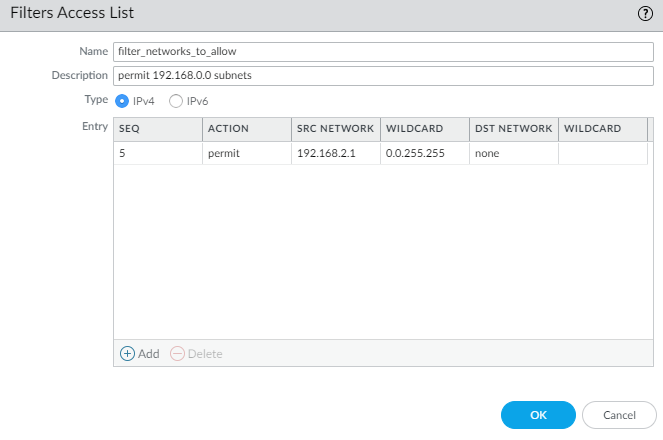
IPv4 Access List Entry. 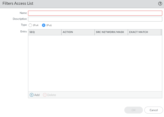
IPv6 Access List Entry. -
Prefix Lists:
Filter routes based on prefix and prefix length range (e.g., /24, ge 26, le 30). More efficient than access lists for prefix matching. Used in BGP filtering, OSPF ABR filtering, Redistribution/BGP route map matching, and Multicast PIM SPT threshold. Sequence matters; implicit deny all at the end.
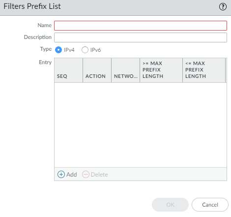
Creating a Prefix List. 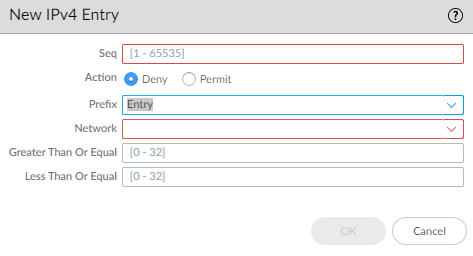
Prefix List IPv4 Entry with Length Ranges. - Redistribution Route Maps: Control redistribution between protocols (BGP, OSPF, RIP, Static, Connected) or into the RIB. Use Match criteria (address lists, prefix lists, AS paths, communities, tags, etc.) and Set actions (metric, metric-type, tag, etc.). Sequence matters; implicit deny all at the end.
- Multicast Route Maps: Filter sources for dynamic IGMP interfaces.
-
AS Path Access Lists (BGP Only):
Filter routes based on AS path using regular expressions. Used for BGP import/export filtering and route map matching. Max 64 rules; implicit permit any at the end.
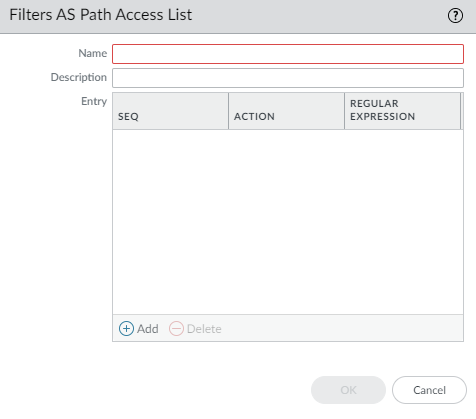
AS Path Access List Entry. -
Community Lists (BGP Only):
Match or remove standard, extended, or large BGP communities. Used in BGP/Redistribution route map matching and Set actions. Sequence matters; implicit deny all at the end.
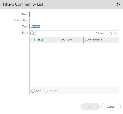
Creating a Community List. 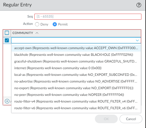
Regular Community List Entry. 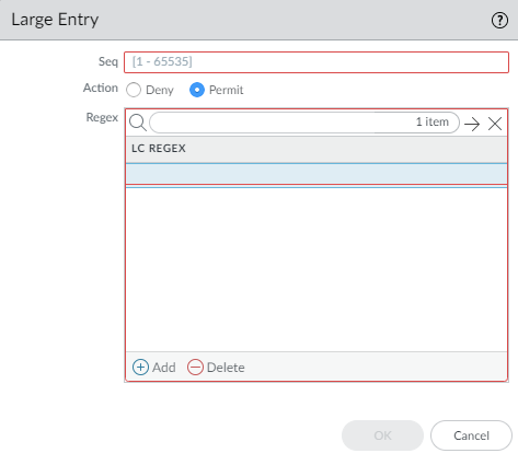
Large Community List Entry. 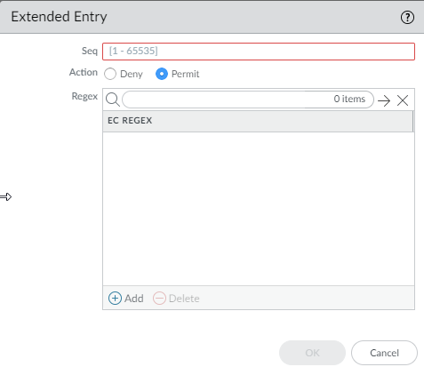
Extended Community List Entry. -
BGP Route Maps (BGP Only):
Advanced control for BGP. Used for default route origination, attribute setting (local pref, MED, origin, community, AS path prepend), NAT next-hop rewriting, filtering (inbound/outbound), conditional advertisement, unsuppressing routes, and aggregate route attribute setting/suppression. Sequence matters; implicit deny all at the end.
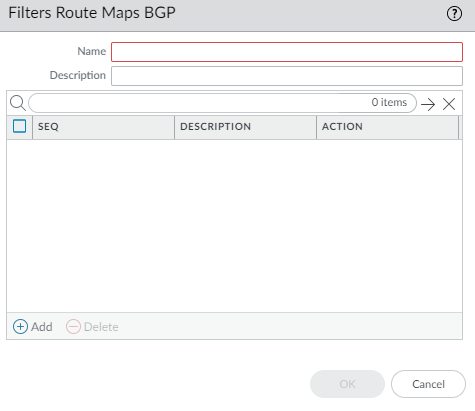
Creating a BGP Route Map. 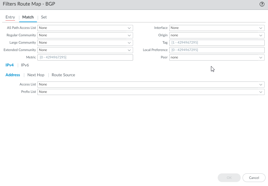
BGP Route Map - Match Criteria. 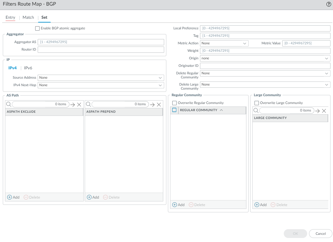
BGP Route Map - Set Actions. 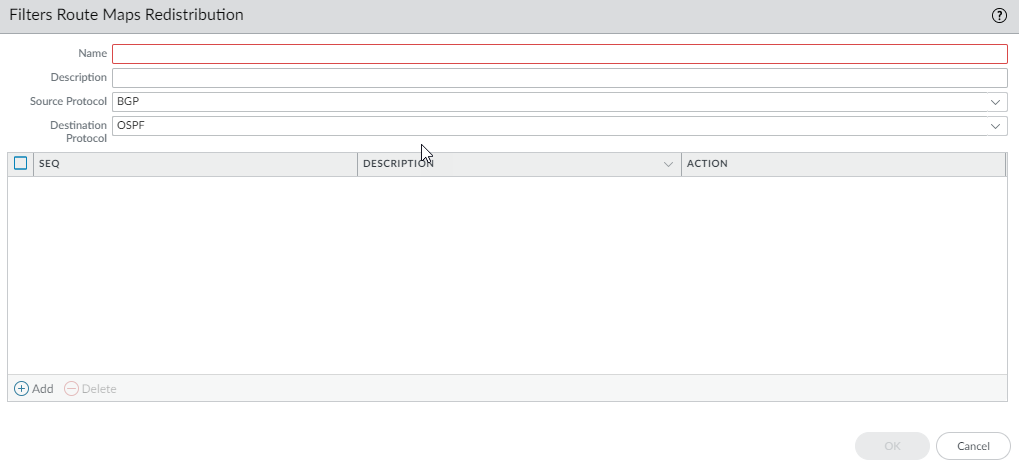
Creating a Redistribution Route Map. 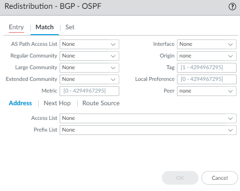
Redistribution Route Map - Match Criteria. 
Redistribution Route Map - Set Actions.
Remember: Filters are evaluated sequentially. The first matching rule determines the outcome (Permit/Deny). Most filters have an implicit deny all at the end (except AS Path lists, which have implicit permit all).
Configure OSPFv2 on an Advanced Routing Engine
The Advanced Routing Engine supports OSPFv2, which supports only IPv4 addressing. Before you configure OSPFv2, you should understand OSPF Concepts .
Consider the OSPF Routing Profiles and filters that you can apply to OSPF and thereby save configuration time and maintain consistency.
- Configure a Logical Router .
-
Enable OSPFv2 and configure general settings.
- Select Network > Routing > Logical Routers and select a logical router.
- Select OSPF and Enable it.
- Enter the Router ID (IPv4 format).
- (Optional) Apply BFD globally by selecting a BFD Profile ( create new , default, or existing). Default is None (Disable BFD).
- Select an OSPF Global General Timer profile or create a new one .
- Select an OSPF Global Interface Timer profile or create a new one .
- Select an OSPF Redistribution Profile or create a new one to redistribute routes into OSPFv2.
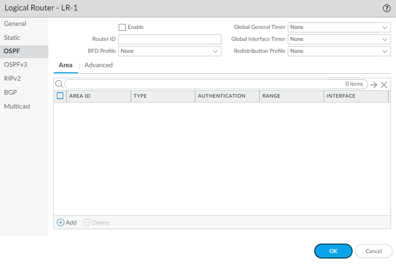
Enabling OSPFv2 and General Settings. -
Create an OSPF area.
- Select Area tab and Add an area identified by its Area ID (x.x.x.x format).
- Select the Type tab. For Authentication , select/create an Authentication profile .
- Select the Type of area: Normal , Stub , or NSSA .
- (Stub/NSSA only) Select no-summary to block Type 3 LSAs.
- (NSSA only) Select Default information originate to advertise a default route. Configure Metric (1-16777214, default 10) and Metric-Type (Type 1 or Type 2).
- (Optional) Select ABR tab to filter prefixes for an Area Border Router. Configure Import-list (Access List), Export-list (Access List), Inbound Filter List (Prefix List), Outbound Filter List (Prefix List). For NSSA ABRs, you can add IPv4 Prefix ranges to summarize Type-7 LSAs into Type-5.
- (Optional) Select Range tab to summarize routes within the area before advertising to the backbone. Add an IP Address/Netmask range. Optionally specify a Substitute address/mask for translation. Choose whether to Advertise (default enabled).
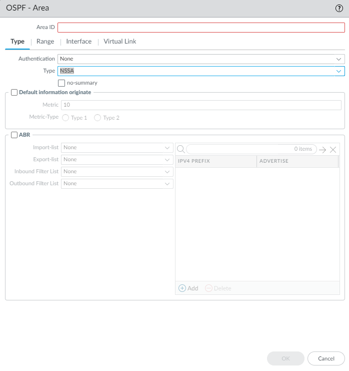
Configuring OSPF Area Type and Options. 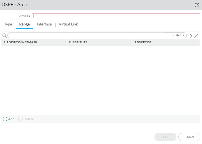
Configuring OSPF Area Range Summarization. -
Configure interfaces within the area.
- Select Interface tab and Add an interface. Enable it.
- Select MTU Ignore if needed (default disabled).
- Select Passive if the interface should advertise its network but not form adjacencies (default disabled).
- Select the Link Type (Broadcast, p2p, p2mp). For p2mp, manually add Neighbors and Priorities.
- Enter OSPF Priority (0-255, default 1). 0 prevents DR/BDR election.
- Select/create an interface-specific Timer Profile to override the global one.
- Select/create an interface-specific Authentication Profile to override the area profile.
- Select/create/disable BFD specifically for this interface ( BFD Profile ), overriding the OSPF global BFD setting. Default is Inherit.
- Enter OSPF Cost for the interface (1-65535, default 10).
- Click OK .
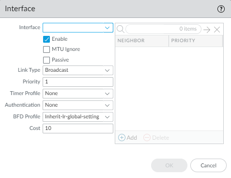
Configuring an OSPF Interface within an Area. -
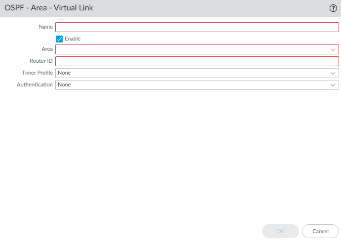
(Optional) Configure a virtual link if the ABR doesn't connect directly to the backbone (Area 0).
- Select Virtual Link tab and Add a link by Name .
- Enable it.
- Select the transit Area .
- Enter the neighbor ABR's Router ID .
- Select/create a virtual link-specific Timer Profile .
- Select/create a virtual link-specific Authentication profile.
- Click OK .
Configuring an OSPF Virtual Link. - Click OK to save the area.
-
(Optional) Configure OSPF Graceful Restart and RFC 1583 compatibility.
- Select OSPF > Advanced tab.
- Select rfc-1583 compatibility if needed (default disabled). Disabling allows multiple paths to ASBR, preventing loops.
- Configure Graceful Restart: Enable Graceful Restart (default enabled), Enable Helper Mode (default enabled), Enable Strict LSA Checking (default enabled).
- Set Grace Period (sec) (5-1800, default 120).
- Set Max Neighbor Restart Time (sec) (5-1800, default 140).
- Click OK .
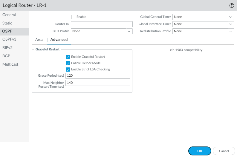
OSPF Advanced Settings. -
(Optional) Configure RIB filtering for OSPFv2 routes.
- Select RIB Filter tab.
- For OSPFv2 Route-Map , select/create a Redistribution Route Map (Source=OSPF, Destination=RIB).
- Click OK .
Configuring RIB Filters for a Logical Router. - (Optional) Change default OSPF administrative distances on the Logical Router > Administrative Distances tab.
- Commit .
- View OSPFv2 runtime information and LSDB via CLI ( show advanced-routing ospf ... ).
Create OSPF Routing Profiles
The Advanced Routing Engine supports OSPFv2; create the following profiles to apply to the protocol, making the configuration easier and more consistent. The profiles can be used across multiple logical routers and virtual systems.
- OSPF Global Timer Profiles —Configure LSA min-arrival and SPF throttle timers. Apply globally in OSPF general config.
- OSPF Interface Authentication Profiles —Specify password or MD5 authentication. Apply to an area, interface, or virtual link.
- OSPF Interface Timer Profiles —Configure hello, dead interval, retransmit, transmit delay, and graceful restart hello delay. Apply globally or per-interface/virtual link.
- OSPF Redistribution Profiles —Specify how to redistribute IPv4 static, connected, BGP, RIPv2, or default routes into OSPFv2. Apply globally in OSPF general config.
-
Create an OSPF Global Timer Profile.
- Select Network > Routing > Routing Profiles > OSPF .
- Add an OSPF Global Timer Profile by Name (max 63 chars, unique, alphanumeric, _, -).
- Enter LSA min-arrival (1-10 sec, default 5). Min time between same LSA instances.
- SPF Throttle: Enter Initial delay (0-600 sec, default 5).
- SPF Throttle: Enter Initial hold time (0-600 sec, default 5).
- SPF Throttle: Enter Maximum hold time (0-600 sec, default 5).
- Click OK .
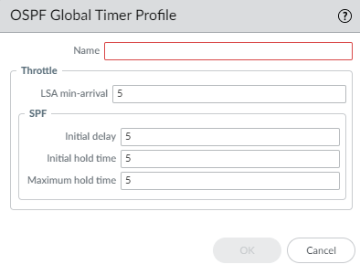
OSPF Global Timer Profile. -
Create an OSPF Interface Authentication Profile.
- Select Network > Routing > Routing Profiles > OSPF .
- Add an OSPF Auth Profile by Name (max 63 chars, unique, alphanumeric, _, -, .).
- Select Type : Password or MD5 .
- If Password , enter Password (max 8 chars) and Confirm.
- If MD5 , Add MD5 Key ID(s) (0-255), enter Key (max 16 alphanumeric), and optionally select Preferred for one key.
- Click OK .
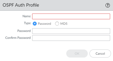
OSPF Auth Profile (Password). 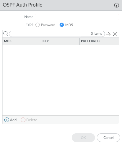
OSPF Auth Profile (MD5). -
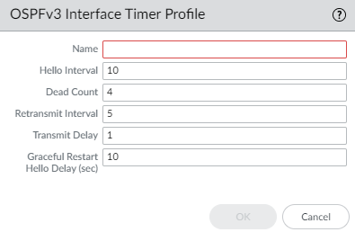
Create an OSPF Interface Timer Profile.
- Select Network > Routing > Routing Profiles > OSPF .
- Add an OSPF Interface Timer Profile by Name (max 63 chars, unique, alphanumeric, _, -, .).
- Enter Hello Interval (1-3600 sec, default 10).
- Enter Dead Count (3-20, default 4). Dead Timer = Hello Interval * Dead Count.
- Enter Retransmit Interval (1-1800 sec, default 5).
- Enter Transmit Delay (1-1800 sec, default 1). LSA age increment before tx.
- Enter Graceful Restart Hello Delay (sec) (1-10 sec, default 10). Used in A/P HA. Ensure Dead Timer is >= 4 * Hello Delay.
- Click OK .
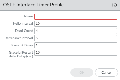
OSPF Interface Timer Profile. -
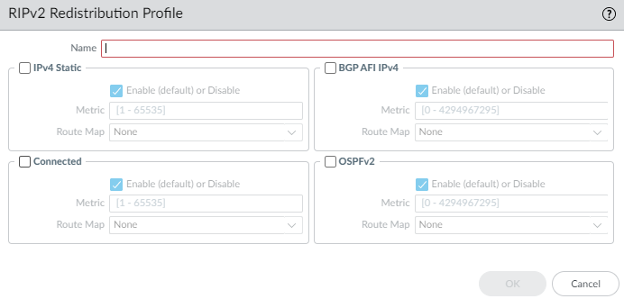
Create an OSPF Redistribution Profile.
- Select Network > Routing > Routing Profiles > OSPF .
- Add an OSPF Redistribution Profile by Name (max 63 chars, unique, alphanumeric, _, -, .).
- Select protocol tab(s) to redistribute ( IPv4 Static , Connected , RIPv2 , BGP AFI IPv4 , IPv4 Default Route ).
-
For each selected protocol:
- Enable redistribution.
- Specify the Metric applied to redistributed routes.
- Specify the Metric-Type (Type 1 or Type 2 (default)).
- (Optional) Select a Redistribute Route-Map ( Redistribution Route Map ) to filter routes and set attributes. Overrides Metric/Metric-Type set here if defined in map.
- For IPv4 Default Route , also select Always if the default route should be advertised even if not present locally (default enabled).
- Click OK .
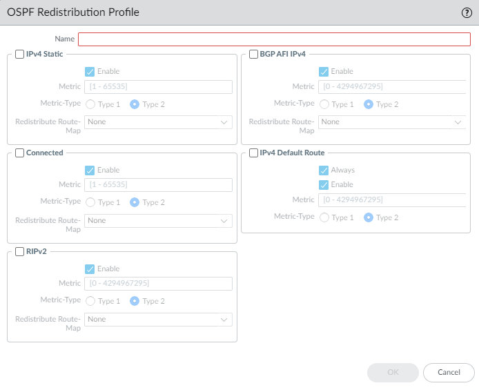
OSPF Redistribution Profile.
Configure OSPFv3 on an Advanced Routing Engine
The Advanced Routing Engine supports OSPFv3, which supports only IPv6 addressing. Before you configure OSPFv3, you should understand OSPF Concepts .
Consider the OSPFv3 Routing Profiles and filters that you can apply to OSPFv3.
- Configure a Logical Router .
-
Configure general OSPFv3 routing options.
- Select Network > Routing > Logical Routers and select the logical router.
- Select OSPFv3 and Enable it.
- Assign a Router ID (IPv4 format).
- (Optional) Apply BFD globally by selecting a BFD Profile ( create new , default, or existing). Default is None.
- Select a Global General Timer profile or create a new one .
- Select a Global Interface Timer profile or create a new one .
- Select a Redistribution Profile or create a new one to redistribute IPv6 routes into OSPFv3.
- Click OK .
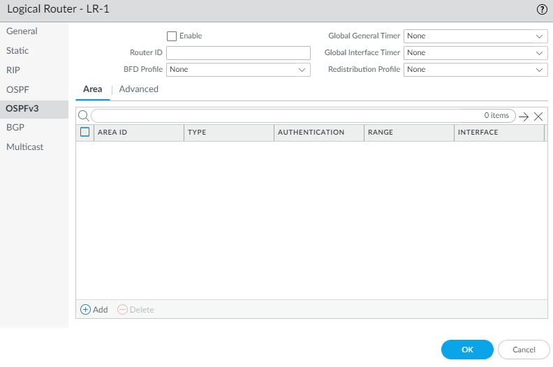
Enabling OSPFv3 and General Settings. -
Create an OSPFv3 area.
- Select Area tab and Add an Area by Area ID (IPv4 format).
- On the Type tab, select an Authentication profile or create a new one . OSPFv3 uses IPSec for authentication.
- Specify the Type of area: Normal , Stub , or NSSA .
- (Stub/NSSA only) Select no-summary to block Type 3 LSAs.
- (NSSA only) Select Default information originate to advertise a default route. Configure Metric (1-16777214, default 10) and Metric-Type (Type 1 or Type 2).
- (Optional) Select ABR tab to filter prefixes for an Area Border Router. Configure Import-list (Access List), Export-list (Access List), Inbound Filter List (Prefix List), Outbound Filter List (Prefix List). For NSSA ABRs, add IPv6 Prefix ranges to summarize Type-7 LSAs.
- (Optional) Select Range tab to summarize routes within the area. Add an IPv6 Address/Netmask range. Choose whether to Advertise (default enabled).
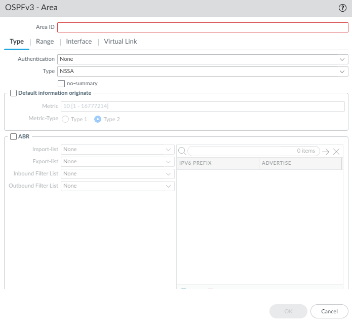
Configuring OSPFv3 Area Type and Options. 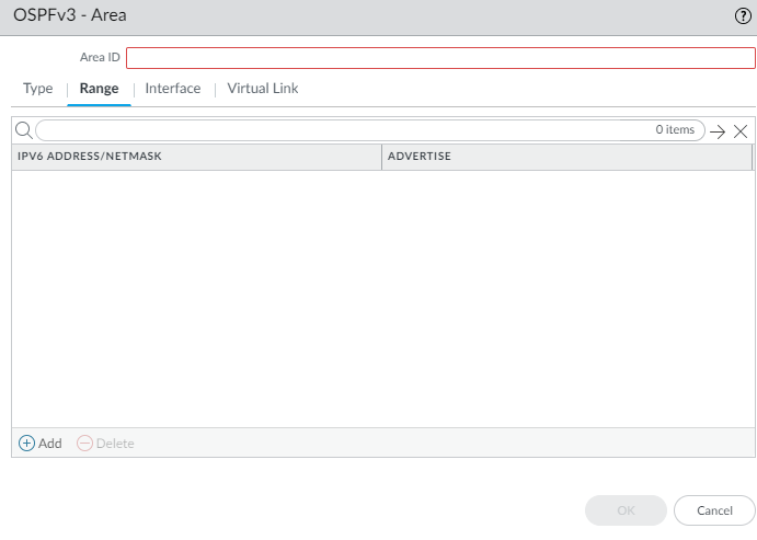
Configuring OSPFv3 Area Range Summarization. -
Add interfaces to the area.
- On the Interface tab, Add an Interface. Enable it.
- Select MTU Ignore if needed (default disabled).
- Select Passive if needed (default disabled).
- Keep Instance ID at 0 (only one instance supported).
- Select Link Type (Broadcast, p2p, p2mp). For p2mp, add Neighbors/Priorities.
- Enter Priority (0-255, default 1). 0 prevents DR/BDR election.
- Select/create an interface-specific Timer Profile .
- Select/create an interface-specific Authentication profile.
- Select/create/disable BFD specifically for this interface ( BFD Profile ). Default is Inherit.
- Enter OSPFv3 Cost (1-65535, default 10).
- Click OK .
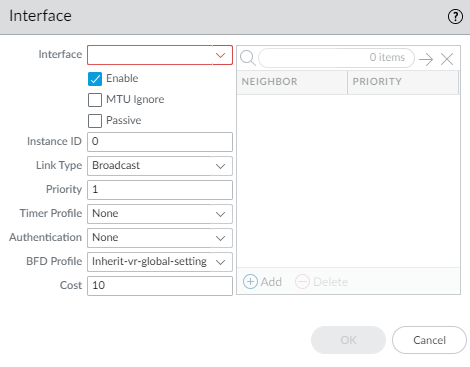
Configuring an OSPFv3 Interface within an Area. -
(Optional) Configure a virtual link if the ABR doesn't connect directly to the backbone (Area 0).
Must be configured within Area 0.0.0.0.
- Select Virtual Link tab and Add link by Name .
- Enable it.
- Select the transit Area .
- Enter neighbor ABR's Router ID .
- Select/create a virtual link-specific Timer Profile .
- Select/create a virtual link-specific Authentication profile.
- Click OK .

Configuring an OSPFv3 Virtual Link. - Click OK to save the area.
-
Configure advanced OSPFv3 features.
- Select OSPFv3 > Advanced tab.
- Configure Graceful Restart: Enable Graceful Restart (default enabled), Enable Helper Mode (default enabled), Enable Strict LSA Checking (default enabled).
- Set Grace Period (sec) (5-1800, default 120).
- Set Max Neighbor Restart Time (sec) (5-1800, default 140).
- Select Disable R-Bit and v6-Bit to indicate router is not active for transit/IPv6 traffic (useful for maintenance).
- Click OK .
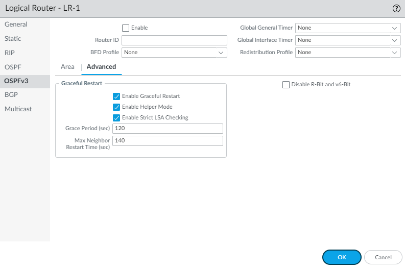
OSPFv3 Advanced Settings. -
(Optional) Configure RIB filtering for OSPFv3 routes.
- Select RIB Filter tab.
- For OSPFv3 Route-Map , select/create a Redistribution Route Map (Source=OSPFv3, Destination=RIB).
- Click OK .
Configuring RIB Filters for a Logical Router. - (Optional) Change default OSPFv3 administrative distances on the Logical Router > Administrative Distances tab.
- Commit .
- View OSPFv3 runtime information and LSDB via CLI ( show advanced-routing ospfv3 ... ).
Create OSPFv3 Routing Profiles
The Advanced Routing Engine supports OSPFv3; create the following profiles to apply to the protocol. They can be used across multiple logical routers and virtual systems.
- OSPFv3 Global Timer Profiles —Specify LSA interval and SPF throttle timers. Apply globally in OSPFv3 general config.
- OSPFv3 Interface Authentication Profiles —Configure IPSec parameters used for OSPFv3 authentication. Apply per area.
- OSPFv3 Interface Timer Profiles —Specify hello, dead interval, retransmit, transmit delay, and graceful restart hello delay. Apply globally or per-interface/virtual link.
- OSPFv3 Redistribution Profiles —Specify how to redistribute IPv6 static, connected, or BGP routes, or the default route into OSPFv3. Apply globally in OSPFv3 general config.
-
Create an OSPFv3 Global Timer Profile.
- Select Network > Routing > Routing Profiles > OSPFv3 .
- Add an OSPFv3 Global Timer Profile by Name (max 63 chars, unique, alphanumeric, _, -).
- Enter LSA min-arrival (1-10 sec, default 5).
- SPF Throttle: Enter Initial delay (0-600 sec, default 5).
- SPF Throttle: Enter Initial hold time (0-600 sec, default 5).
- SPF Throttle: Enter Maximum hold time (0-600 sec, default 5).
- Click OK .
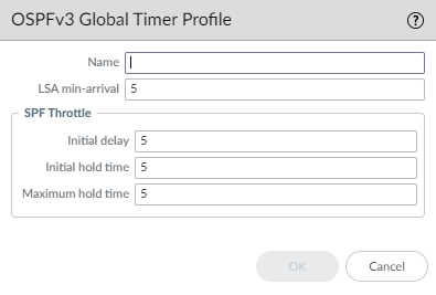
OSPFv3 Global Timer Profile. -
Create an OSPFv3 Interface Authentication Profile.
- Select Network > Routing > Routing Profiles > OSPFv3 .
- Add an OSPFv3 Auth Profile by Name (max 63 chars, unique, alphanumeric, _, -, .).
- Enter the SPI (Security Policy Index, 0-4294967295), must match peer.
- Select Protocol : ESP (recommended) or AH .
- Select Authentication Type (SHA1 (default), SHA256, SHA384, SHA512, MD5, None).
- Enter authentication Key (hexadecimal, 40 chars for SHA1/MD5) and Confirm Key .
- (ESP only) Select encryption Algorithm (3des (default), aes-128/192/256-cbc, null).
- (ESP only) Enter encryption Key (hexadecimal, correct length for algorithm) and Confirm Key .
- Click OK .
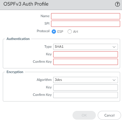
OSPFv3 Authentication Profile (IPSec). -
Create an OSPFv3 Interface Timer Profile.
- Select Network > Routing > Routing Profiles > OSPFv3 .
- Add an OSPFv3 Interface Timer Profile by Name (max 63 chars, unique, alphanumeric, _, -, .).
- Enter Hello Interval (1-3600 sec, default 10).
- Enter Dead Count (3-20, default 4).
- Enter Retransmit Interval (1-1800 sec, default 5).
- Enter Transmit Delay (1-1800 sec, default 1).
- Enter Graceful Restart Hello Delay (sec) (1-10 sec, default 10).
- Click OK .
OSPFv3 Interface Timer Profile. -
Create an OSPFv3 Redistribution Profile.
- Select Network > Routing > Routing Profiles > OSPFv3 .
- Add an OSPFv3 Redistribution Profile by Name (max 63 chars, unique, alphanumeric, _, -, .).
- Select protocol tab(s) to redistribute ( IPv6 Static , Connected , BGP AFI IPv6 , IPv6 Default Route ).
-
For each selected protocol:
- Enable redistribution.
- Specify the Metric .
- Select Metric Type (Type 1 or Type 2).
- (Optional) Select a Redistribute Route-Map ( Redistribution Route Map ) to filter/set attributes.
- For IPv6 Default Route , also select Always if needed (default enabled).
- Click OK .
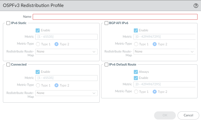
OSPFv3 Redistribution Profile. - Commit your changes.
Configure RIPv2 on an Advanced Routing Engine
The Advanced Routing Engine supports RIPv2.
Consider the RIPv2 Routing Profiles and filters that you can apply.
- Configure a Logical Router .
-
Enable RIPv2 and configure general settings.
- Select Network > Routing > Logical Routers and select a logical router.
- Select RIPv2 and Enable it.
- Select advertise default route in RIP if needed (advertise 0.0.0.0/0 even if not in local RIB).
- (Optional) Apply BFD globally by selecting a BFD Profile . Default is None.
- Select a Global General Timer or create a new one .
- Select an Auth Profile or create a new one .
- Select a Redistribution Profile or create a new one to redistribute routes into RIPv2.
- (Optional) Select a Global Inbound Distribute List (Access List) to filter received routes.
- (Optional) Select a Global Outbound Distribute List (Access List) to filter advertised routes.
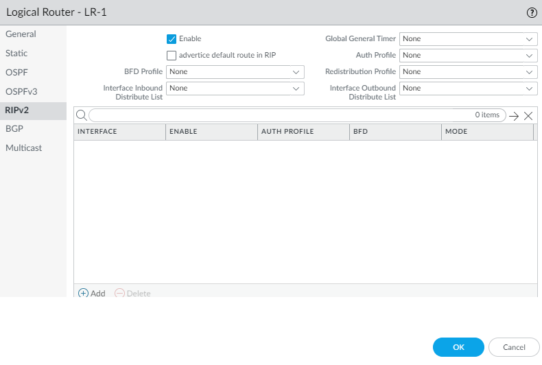
Enabling RIPv2 and General Settings. -
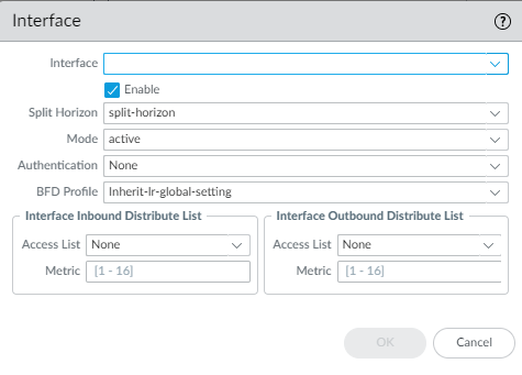
Configure an interface for RIPv2.
- Select Interface tab and Add an interface. Enable it.
- For Split Horizon , select: split-horizon (default), no-split-horizon , or no-split-horizon-with-poison-reverse .
- Select the Mode : active (send/receive updates), passive (advertise network, no updates sent), send-only .
- Select an interface-specific Authentication profile to override the global one.
- Select/create/disable BFD specifically for this interface ( BFD Profile ). Default is Inherit.
- For Interface Inbound Distribute List , select/create an Access List to filter routes received on this interface.
- Specify the Metric applied to incoming routes (1-16).
- For Interface Outbound Distribute List , select/create an Access List to control routes advertised out this interface.
- Specify the Metric to apply to advertised routes (1-16).
- Click OK .
Configuring a RIPv2 Interface. - Click OK .
-
(Optional) Control RIP routes placed in the global RIB using a RIB Filter.
- Select RIB Filter tab.
- For RIP Route-Map , select/create a Redistribution Route Map (Source=RIP, Destination=RIB).
- Click OK .
Configuring RIB Filters for a Logical Router. - (Optional) Change default RIP administrative distance on the Logical Router > Administrative Distances tab.
- Commit .
- View RIPv2 runtime info via CLI ( show advanced-routing rip ... ).
Create RIPv2 Routing Profiles
The Advanced Routing Engine supports RIPv2; create the following profiles to apply to the protocol.
- RIPv2 Global Timer Profiles —Specify update, expire, and delete intervals. Apply globally in RIPv2 general config.
- RIPv2 Interface Authentication Profiles —Specify password or MD5 authentication. Apply globally or per interface.
- RIPv2 Redistribution Profiles —Specify how to redistribute IPv4 static, connected, BGP, or OSPFv2 routes into RIPv2. Apply globally in RIPv2 general config.
-
Create a RIPv2 Global Timer Profile.
- Select Network > Routing > Routing Profiles > RIPv2 .
- Add a RIPv2 Global Timer Profile by Name (max 63 chars, unique, alphanumeric, _, -).
- Specify Update Interval (5-2,147,483,647 sec, default 30).
- Specify Expire Interval (5-2,147,483,647 sec, default 180).
- Specify Delete Interval (5-2,147,483,647 sec, default 120).
- Click OK .
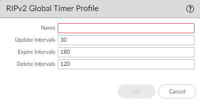
RIPv2 Global Timer Profile. -
Create a RIPv2 Authentication Profile.
- Select Network > Routing > Routing Profiles > RIPv2 .
- Add a RIPv2 Authentication Profile by Name (max 63 chars, unique, alphanumeric, _, -, .).
- Specify type : md5 or password .
- For password , enter Password (max 16 chars) and Confirm.
- For md5 : Add MD5 Key-ID (0-255), enter Key (max 16 alphanumeric), Confirm Key, and optionally select use this key when sending packet (Preferred).
- Click OK .
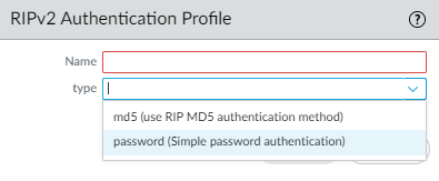
RIPv2 Authentication Profile Type Selection. 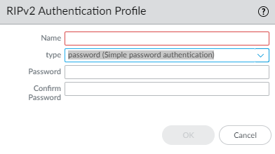
RIPv2 Auth Profile (Password). 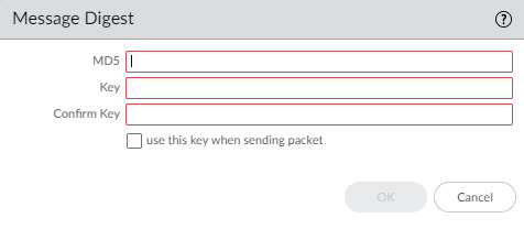
RIPv2 Auth Profile (MD5). -
Create a RIPv2 Redistribution Profile.
- Select Network > Routing > Routing Profiles > RIPv2 .
- Add a RIPv2 Redistribution Profile by Name (max 63 chars, unique, alphanumeric, _, -, .).
- Select protocol tab(s) to redistribute ( IPv4 Static , Connected , BGP AFI IPv4 , OSPFv2 ).
-
For each selected protocol:
- Enable redistribution.
- Specify the Metric applied to redistributed routes.
- (Optional) Select a Redistribute Route-Map ( Redistribution Route Map ) to filter/set attributes. Overrides Metric set here if defined in map.
- Click OK .
RIPv2 Redistribution Profile. - Commit your changes.
Create BFD Profiles
On an Advanced Routing Engine, you can use Bidirectional Forwarding Detection (BFD) profiles to easily apply BFD settings to a static route or routing protocol (BGP, OSPFv2, OSPFv3, RIPv2). You can use the default profile (read-only) or create new ones.
Before creating a BFD profile, ensure you have configured the Logical Router and the relevant static routes or dynamic routing protocols.
The effectiveness of BFD depends on factors like traffic load, network conditions, aggressiveness of settings, and dataplane load. Session-based firewalls may require longer intervals and higher multipliers than dedicated routers.
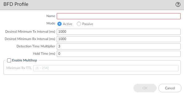
- Select Network > Routing > Routing Profiles > BFD .
- Add a BFD profile by Name (max 63 chars, unique, case-sensitive, alphanumeric, -, _).
- Select the Mode : Active (initiates control packets, default) or Passive (waits for peer). At least one peer must be Active.
-
Enter
Desired Minimum Tx Interval (ms)
: Minimum interval to send BFD packets.
- PA-7k/5400/5200: 50-10000ms (>=100ms recommended for PA-7k)
- PA-3200: 100-10000ms
- VM-Series: 200-10000ms
- Default: 1000ms
- Use the same Tx interval if multiple protocols use BFD on the same interface.
-
Enter
Required Minimum Rx Interval (ms)
: Minimum interval to receive BFD packets. (Ranges/Defaults same as Tx).
- >=100ms recommended for PA-7k.
-
Enter
Detection Time Multiplier
(2-255, default 3). Number of missed packets before declaring failure.
Detection Time = Peer's Multiplier * Agreed Tx Interval.
Too short can cause false failures. - Enter Hold Time (ms) : Delay after link-up before sending BFD packets (Active mode only). 0-120000ms, default 0 (no delay).
- Enter Minimum Rx TTL : Min TTL accepted in received BFD packets for multihop BGP BFD (1-254, no default).
- Click OK .
- Apply the profile when configuring static routes or routing protocols.
- Commit .
Configure IPv4 Multicast
The Advanced Routing Engine supports IPv4 multicast for a logical router. You should be familiar with IP Multicast , IGMP , and PIM concepts.
Advanced Routing Engine multicast features not in legacy:
- IGMP static join.
- PIM RPF lookup modes (MRIB only, URIB only, MRIB-then-URIB).
IPv4 multicast does not support IGMPv1.
Use Multicast Routing Profiles for PIM/IGMP timers and Multicast Route Maps for PIM group permissions.
- Configure a Logical Router .
- Select Network > Routing > Logical Routers and select a logical router.
- Select Multicast and enable multicast protocol .
-
Configure general PIM parameters.
- Select PIM > General and Enable PIM.
- Select the RPF lookup mode : mrib-only , mrib-then-urib , or urib-only . This determines where PIM looks for the route back to the source for RPF checks and Join messages.
- For Interface General Timer , select/create an IPv4 PIM Interface Timer profile (default None).
- Specify Route Age Out Time (sec) (210-7200, default 210). Time mroute stays in MRIB after session ends.
- (Optional - SSM) For Multicast SSM Range , select/create a Prefix List of allowed sources (default None).
- (Optional - SPT Threshold) Add a Group Address (Prefix List) and specify the Threshold rate (kbps) to switch from shared tree (RP) to shortest-path tree (SPT): 0 (switch on first packet) (default), a specific rate (0-4294967295), or never (do not switch to spt) .
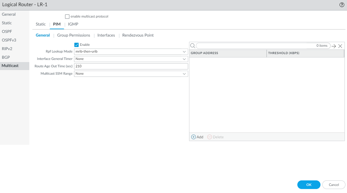
Enabling PIM and General Settings. -
(Optional) Specify PIM group permissions.
- Select PIM > Group Permissions tab.
-
For
Source Group List
, select/create an
Access List
to control allowed (S,G) pairs transiting the router (default None).
Modifying this does not retroactively clear existing mroutes.
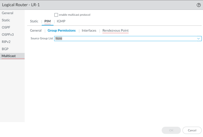
PIM Group Permissions. -
Configure PIM characteristics for interfaces.
- Select PIM > Interfaces tab and Add an interface by Name .
- Enter a Description .
- Specify DR Priority (1-4294967295, default 1). Higher value wins DR election on multiaccess segments.
- Send BSM : Allow Bootstrap Messages (enabled by default). Advanced Routing Engine cannot be a BSR.
- Select an interface-specific Timer Profile to override the global one (default None).
- Specify a Neighbor Filter (Access List) to control allowed PIM neighbors.
- Click OK .
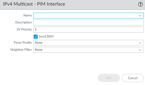
Configuring a PIM Interface. -
(ASM only) Configure a PIM Rendezvous Point (RP). Can configure both static and candidate.
- Select PIM > Rendezvous Point tab.
- Select local RP Type : Static RP or Candidate RP (default None).
- If Static RP :
- Select RP Interface and Address .
- Select Override learned RP... to prefer this static RP over dynamic ones for the specified groups.
- Select Group List (Access List) for which this RP is authoritative.
- If Candidate RP :
- Select Candidate RP Interface and Address .
- Specify Priority (0-255, default 192). Lower value is higher priority.
- Specify Advertisement Interval (1-26214 sec, default 60).
- Select Group List (Access List) for which this device is a candidate RP (default None = candidate for all groups).
- (Optional - Static RP) Add remote Static RPs by specifying their IPv4 Address and the Group List (Access List) they serve. Select Override to prefer the static remote RP over dynamically learned ones.
- Click OK .
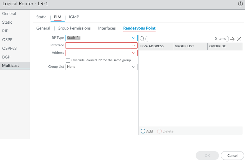
Configuring a Static RP. 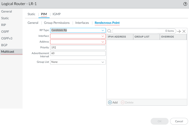
Configuring a Candidate RP. - Click OK to save PIM settings.
-
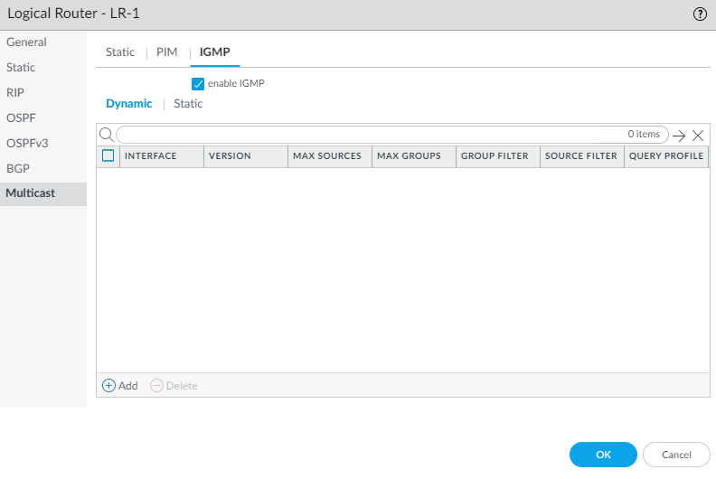
Configure IGMP on interfaces facing multicast receivers.
- Select IGMP tab and enable IGMP .
- To configure a dynamic IGMP interface, select Dynamic sub-tab.
- Add an Interface .
- Select IGMP Version : 2 or 3 .
- Select Robustness value (1-7, default 2). Affects query/leave timers.
- Select Group Filter (Access List) to control accepted Joins (default None).
- Set Max Groups (1-65535, default unlimited).
- Set Max Sources (1-65535, default unlimited).
- Select Query Profile ( IGMP Interface Query profile ) (default None).
- (Optional) Select drop IGMP packets without Router Alert option (default disabled).
- Click OK .
- To configure a static IGMP interface, select Static sub-tab. (New in Advanced Routing)
- Add a static interface entry by Name .
- Select the Interface .
- Enter the multicast Group Address .
- Enter the multicast Source Address for this (S,G) join.
- Click OK .
Enabling IGMP. 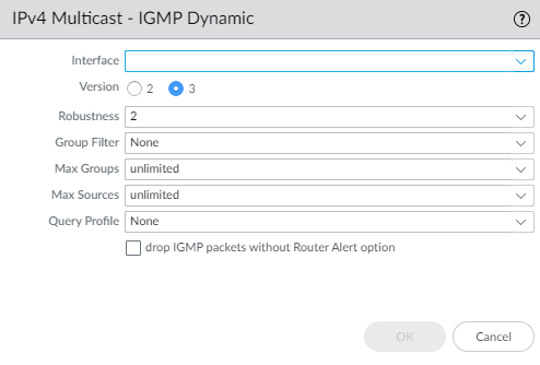
Configuring a Dynamic IGMP Interface. 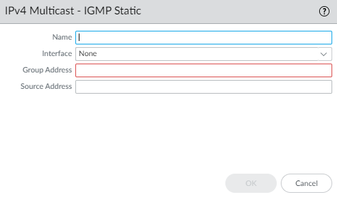
Configuring a Static IGMP Join. - Click OK to save Multicast configuration.
- Commit .
Configure MSDP
Advanced Routing mode supports Multicast Source Discovery Protocol (MSDP) in PIM Sparse Mode (PIM-SM) to discover multicast sources across different PIM domains or autonomous systems. MSDP peers exchange Source-Active (SA) messages containing (S,G) information.

MSDP uses TCP port 639. The higher IP address peer listens, the lower IP address peer connects. It requires an underlying unicast routing infrastructure (typically BGP) for RPF checks between domains.
Before configuring MSDP, ensure IPv4 multicast is configured and consider creating MSDP authentication and timer profiles .
- Configure a Logical Router and Enable Multicast .
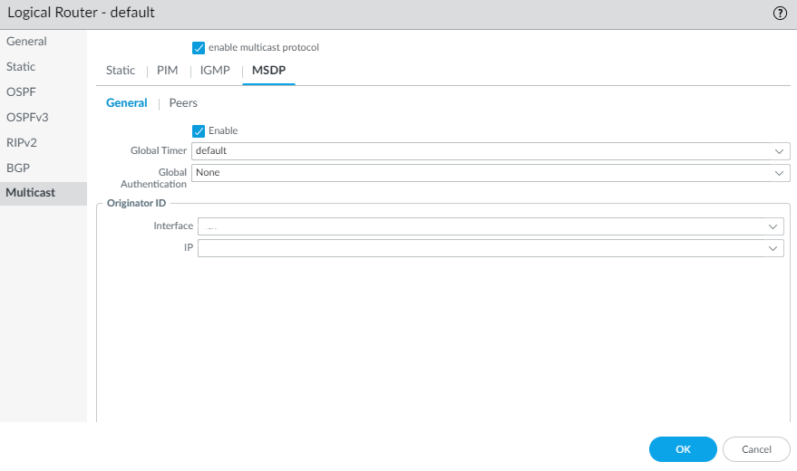
- Select Network > Routing > Logical Routers > (select router) > Multicast > MSDP > General .
- Enable MSDP.
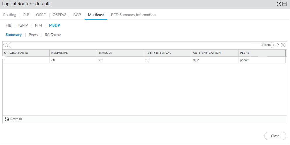
- Select the Global Timer profile (default, existing, or new). Default timers: Keep Alive 60s, Timeout 75s, Retry 30s.
- Select the Global Authentication profile (None (default), existing, or new). Uses MD5.
- For Originator ID , select the Interface and IP Address used as the RP address in outgoing SA messages.
- Click OK .
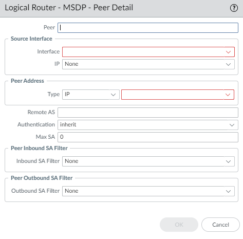
- Select Peers tab and Add a Peer by Name (max 63 chars, unique, alphanumeric, _, -, .).
- Select the Source Interface and IP address for the TCP connection.
- Select Peer Address Type ( IP or FQDN ) and provide the peer's address/name.
- Enter the Remote AS number of the peer.
- Select Authentication behavior: inherit global, select specific profile, or None (disable).
- Enter Max SA entries accepted from this peer (0-1024, 0=unlimited).
- (Optional) Select Peer Inbound SA Filter (Access List) to filter received SA messages.
- (Optional) Select Peer Outbound SA Filter (Access List) to filter SA messages sent to this peer.
- Click OK .
- Commit .
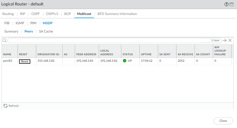
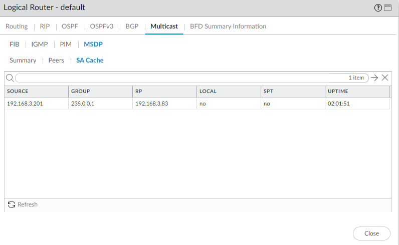
- View MSDP runtime stats: Network > Routing > Logical Routers > (select router) > More Runtime Stats > Multicast > MSDP (Summary, Peers, SA Cache).
Create Multicast Routing Profiles
On an Advanced Routing Engine, create profiles for IPv4 multicast PIM, IGMP, and MSDP configurations.
-
Create a multicast IPv4 PIM Interface Timer profile. (Used in PIM General & Interface config).
- Select Network > Routing > Routing Profiles > Multicast .
- Add a Multicast IPv4 PIM Interface Timer Profile by Name .
- Specify Assert Interval (1-65534 sec, default 177).
- Specify Hello Interval (1-180 sec, default 30).
- Specify Join Prune Interval (60-600 sec, default 60).
- Click OK .
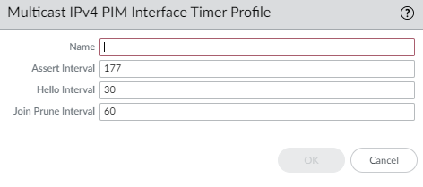
PIM Interface Timer Profile. -
Create a multicast IPv4 IGMP Interface Query profile. (Used for Dynamic IGMP interfaces).
- Select Network > Routing > Routing Profiles > Multicast .
- Add a Multicast IPv4 IGMP Interface Query Profile by Name .
- Specify Max Query Response Time (1-25 sec, default 10).
- Specify Query Interval (1-1800 sec, default 125).
- Specify Last Member Query Interval (1-25 sec, default 1).
- (Optional) Enable leave group immediately when a leave message is received (default disabled).
- Click OK .
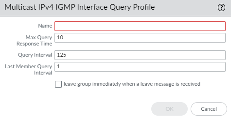
IGMP Interface Query Profile. -
Create an MSDP Authentication Profile. (Used in MSDP General/Peer config).
- Select Network > Routing > Routing Profiles > Multicast .
- Add a Multicast MSDP Authentication Profile by Name .
- Enter MD5 Secret and Confirm Secret .
- Click OK .
-
Create an MSDP Timer Profile. (Used in MSDP General config).
- Select Network > Routing > Routing Profiles > Multicast .
- Add a Multicast MSDP Timer Profile by Name .
- Enter Keep Alive Interval (1-60 sec, default 60).
- Enter Message Timeout interval (1-75 sec, default 75).
- Enter Connection Retry Interval (1-60 sec, default 30).
- Click OK .
- Commit your changes.
Create an IPv4 MRoute
An mroute is a static unicast route pointing towards a multicast source, stored in the multicast RIB (MRIB). PIM uses this for RPF checks when configured, allowing multicast traffic to potentially take a different path than unicast traffic (e.g., through a tunnel if intermediate devices don't support multicast).
Whether PIM uses the MRIB or URIB for RPF checks depends on the RPF lookup mode configured for PIM .
- Configure a Logical Router and Enable Multicast .
- Select Network > Routing > Logical Routers and select a logical router.
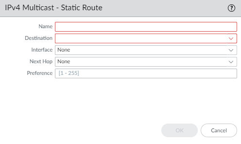
- Select Multicast > Static tab.
- Add an mroute by Name (alphanumeric, _, -).
- Enter the Destination (IPv4 Address/Mask or address object) of the multicast source/subnet for RPF checks.
- Select the egress Interface for the unicast route towards the source.
- Enter the IPv4 address (or address object) of the Next Hop router towards the source.
- Enter a Preference (Admin Distance) for the route (1-255).
- Click OK .
- Click OK again to save Multicast config.
- Commit your changes.
Diagrams
Enabling Advanced Routing Flow
Flowchart illustrating the process of enabling the Advanced Routing Engine.
BGP Peering Configuration Steps (Simplified)
Simplified flowchart for basic BGP configuration steps.
Interactive Quiz
Test your knowledge of Palo Alto Advanced Routing. Please answer all questions before submitting.