Large Scale VPN (LSVPN) Fundamentals
The GlobalProtect Large Scale VPN (LSVPN) feature on the Palo Alto Networks Next-Generation Firewall simplifies the deployment of traditional hub and spoke VPNs, enabling you to deploy enterprise networks with several branch offices quickly with a minimum amount of configuration required on the remote satellites . This solution uses certificates for firewall authentication and IPSec to secure data.
LSVPN enables site-to-site VPNs between Palo Alto Networks firewalls. To set up a site-to-site VPN between a Palo Alto Networks firewall and another device, see VPNs. The LSVPN doesn’t require a GlobalProtect subscription.
LSVPN is designed for Palo Alto Networks firewalls acting as hub (Gateway) and spokes (Satellites).
A GlobalProtect subscription is NOT required for LSVPN functionality.
The following topics describe the LSVPN components and how to set them up to enable site-tosite VPN services between Palo Alto Networks firewalls:
-
LSVPN Overview
-
Create Interfaces and Zones for the LSVPN
-
Enable SSL Between GlobalProtect LSVPN Components
-
Configure the Portal to Authenticate Satellites
-
Configure GlobalProtect Gateways for LSVPN
-
Configure the GlobalProtect Portal for LSVPN
-
Prepare the Satellite to Join the LSVPN
-
Verify the LSVPN Configuration
-
LSVPN Quick Configs
LSVPN Overview
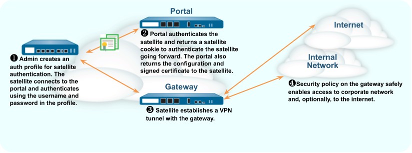
GlobalProtect provides a complete infrastructure for managing secure access to corporate resources from your remote sites. This infrastructure includes the following components:
-
GlobalProtect Portal —Provides the management functions for your GlobalProtect LSVPN infrastructure. Every satellite that participates in the GlobalProtect LSVPN receives configuration information from the portal, including configuration information to enable the satellites (the spokes) to connect to the gateways (the hubs). You configure the portal on an interface on any Palo Alto Networks Next-Generation Firewall.
-
GlobalProtect Gateways —A Palo Alto Networks firewall that provides the tunnel endpoint for satellite connections. The Satellites access resources that you protect using Security policy rules on the gateway. It isn’t required to have a separate portal and gateway; a single firewall can function both as portal and gateway.
-
GlobalProtect Satellite —A Palo Alto Networks firewall at a remote site that establishes IPSec tunnels with one or more gateways at your corporate office(s) for secure access to centralized resources. Configuration on the satellite firewall is minimal, enabling you to scale your VPN quickly and easily as you add new sites.
Portal: Manages configuration for Satellites.
Gateway: Hub device, terminates IPSec tunnels from Satellites.
Satellite: Spoke device at remote site, connects to Gateways.
A single firewall can act as both Portal and Gateway. This is a common deployment for smaller setups.
The following diagram illustrates how the GlobalProtect LSVPN components work together.
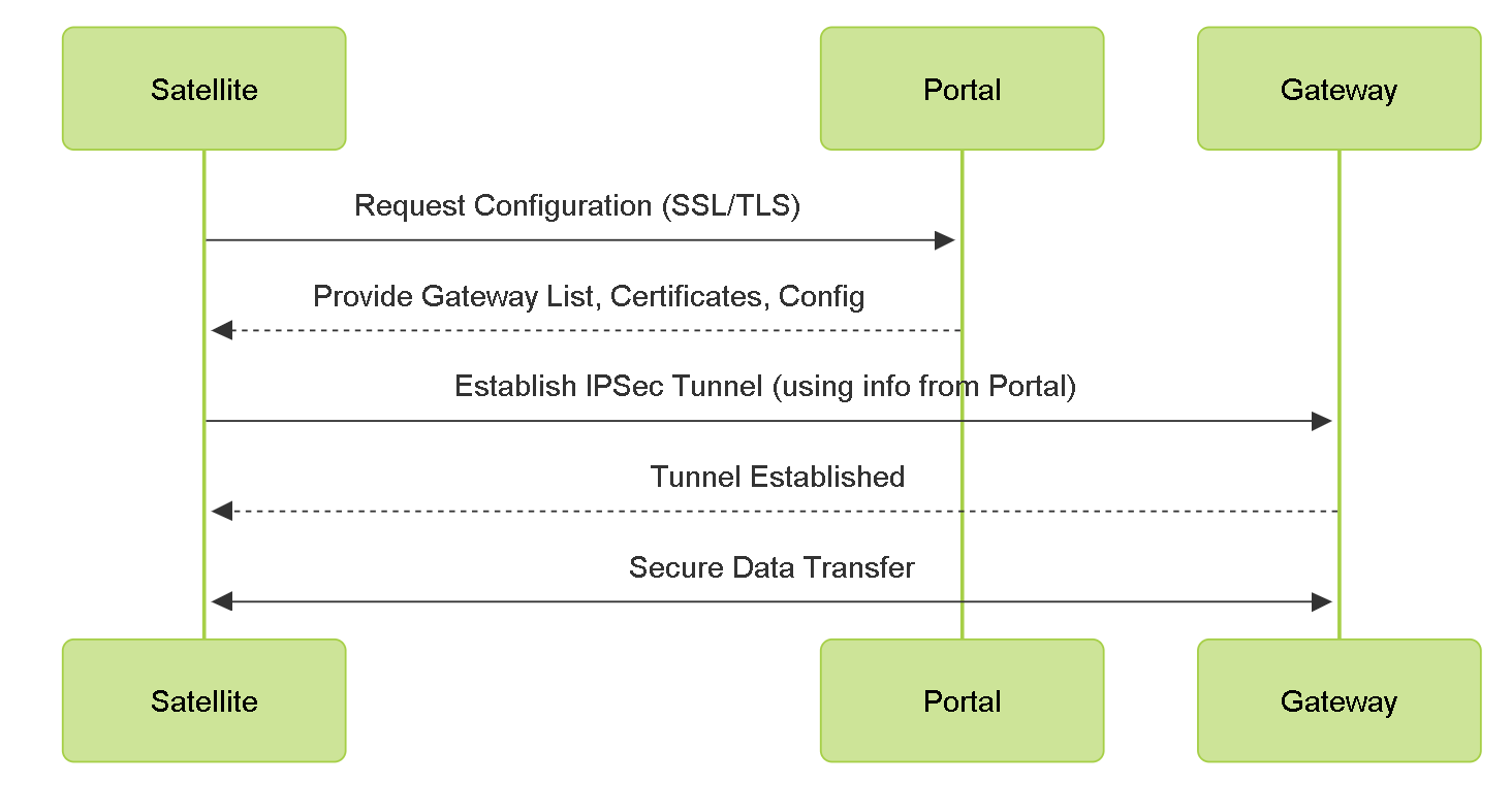
LSVPN Component Interaction Flow.
Create Interfaces and Zones for the LSVPN
Configure the following interfaces and zones for your LSVPN infrastructure:
-
GlobalProtect portal —Requires a Layer 3 interface for GlobalProtect satellites to connect to. If the portal and gateway are on the same firewall, they can use the same interface. The portal must be in a zone that is accessible from your branch offices.
-
GlobalProtect gateways —Requires three interfaces: a Layer 3 interface in the zone that is reachable by the remote satellites, an internal interface in the trust zone that connects to the protected resources, and a logical tunnel interface for terminating the VPN tunnels from the satellites. Unlike other site-to-site VPN solutions, the GlobalProtect gateway only requires a single tunnel interface, which it will use for tunnel connections with all of your remote satellites (point-to-multipoint). If you plan to use dynamic routing, you must assign an IP address to the tunnel interface. GlobalProtect supports both IPv6 and IPv4 addressing for the tunnel interface.
-
GlobalProtect satellites —Requires a single tunnel interface for establishing a VPN with the remote gateways (up to a maximum of 25 gateways). If you plan to use dynamic routing, you must assign an IP address to the tunnel interface. GlobalProtect supports both IPv6 and IPv4 addressing for the tunnel interface.
Gateway Tunnel Interface: A single logical tunnel interface on the Gateway can terminate connections from multiple Satellites (point-to-multipoint).
Tunnel IP Address: Required for dynamic routing, optional but useful for troubleshooting otherwise.
User-ID should be enabled on the zone where VPN tunnels terminate on the Gateway for visibility.
For more information about portals, gateways, and satellites see LSVPN Overview.
STEP 1 | Configure a Layer 3 interface.
The portal and each gateway and satellite all require a Layer 3 interface to enable traffic to be routed between sites.
If the gateway and portal are on the same firewall, you can use a single interface for both components.
-
Select Network > Interfaces > Ethernet and then select the interface you want to configure for GlobalProtect LSVPN.
-
Select Layer3 from the Interface Type drop-down.
-
On the Config tab, select the Security Zone to which the interface belongs:
-
The interface must be accessible from a zone outside of your trust network. Consider creating a dedicated VPN zone for visibility and control over your VPN traffic.
-
If you haven’t yet created the zone, select New Zone from the Security Zone dropdown, define a Name for the new zone, and then click OK .
-
-
Select the Virtual Router to use.
-
Assign an IP address to the interface:
-
For an IPv4 address, select IPv4 and Add the IP address and network mask to assign to the interface, for example 203.0.11.100/24.
-
For an IPv6 address, select IPv6 , Enable IPv6 on the interface , and Add the IP address and network mask to assign to the interface, for example 2001:1890:12f2:11::10.1.8.160/80.
-
-
To save the interface configuration, click OK .
STEP 2 | On the firewall(s) hosting the GlobalProtect gateway(s), configure the logical tunnel interface that will terminate VPN tunnels established by the GlobalProtect satellites.
-
Select Network > Interfaces > Tunnel and click Add .
-
In the Interface Name field, specify a numeric suffix, such as .2 .
-
On the Config tab, expand the Security Zone drop-down to define the zone as follows:
-
To use your trust zone as the termination point for the tunnel, select the zone from the drop-down.
-
(Recommended) To create a separate zone for VPN tunnel termination, click New Zone . In the Zone dialog, define a Name for the new zone (for example lsvpn-tun ), select the Enable User Identification check box, and then click OK .
-
-
Select the Virtual Router .
-
(Optional) To assign an IP address to the tunnel interface:
-
For an IPv4 address, select IPv4 and Add the IP address and network mask to assign to the interface, for example 203.0.11.100/24.
-
For an IPv6 address, select IPv6 , Enable IPv6 on the interface , and Add the IP address and network mask to assign to the interface, for example 2001:1890:12f2:11::10.1.8.160/80.
-
-
To save the interface configuration, click OK .
STEP 3 | If you created a separate zone for tunnel termination of VPN connections, create a security policy to enable traffic flow between the VPN zone and your trust zone.
For example, a policy rule enables traffic between the lsvpn-tun zone and the L3-Trust zone.
STEP 4 | Commit your changes.
Click Commit .
Enable SSL Between GlobalProtect LSVPN Components
All interaction between the GlobalProtect components occurs over an SSL/TLS connection. Therefore, you must generate and/or install the required certificates before configuring each component so that you can reference the appropriate certificate(s) and/or certificate profiles in the configurations for each component.
SSL/TLS is fundamental for communication between Portal, Gateways, and Satellites.
Certificates are used for mutual authentication.
About Certificate Deployment
There are two basic approaches to deploying certificates for GlobalProtect LSVPN:
-
Enterprise Certificate Authority —If you already have your own enterprise certificate authority, you can use this internal CA to issue an intermediate CA certificate for the GlobalProtect portal to enable it to issue certificates to the GlobalProtect gateways and satellites. You can also configure the GlobalProtect portal to act as a Simple Certificate Enrollment Protocol (SCEP) client to issue client certificates to GlobalProtect satellites.
-
Self-Signed Certificates —You can generate a self-signed root CA certificate on the firewall and use it to issue server certificates for the portal, gateway(s), and satellite(s). When using self-signed root CA certificates, as a best practice, create a self-signed root CA certificate on the portal and use it to issue server certificates for the gateways and satellites. This way, the private key used for certificate signing stays on the portal.
When using self-signed certificates, ensure the Root CA certificate is trusted by all LSVPN components (Portal, Gateways, Satellites). Satellites need to trust the Portal's server certificate issuer, and Gateways/Satellites need to trust each other's certificate issuers.
Deploy Server Certificates to the GlobalProtect LSVPN Components
The GlobalProtect LSVPN components use SSL/TLS to authenticate mutually. Before deploying the LSVPN, you must assign an SSL/TLS service profile to each portal and gateway. The profile specifies the server certificate and allowed TLS versions for communication with satellites. You don’t need to create SSL/TLS service profiles for the satellites because the portal will issue a server certificate for each satellite during the first connection as part of the satellite registration process.
In addition, you must import the root certificate authority (CA) certificate used to issue the server certificates onto each firewall that you plan to host as a gateway or satellite. Finally, on each gateway and satellite participating in the LSVPN, you must configure a certificate profile that will enable them to establish an SSL/TLS connection using mutual authentication.
The following workflow shows the best practice steps for deploying SSL certificates to the GlobalProtect LSVPN components:
STEP 1 | On the firewall hosting the GlobalProtect portal, create the root CA certificate for signing the certificates of the GlobalProtect components.
Create a Self-Signed Root CA Certificate:
-
Select Device > Certificate Management > Certificates , then Device Certificates . Select Generate .
-
Enter a Certificate Name , such as LSVPN_CA .
-
Don’t select a value in the Signed By field (this is what indicates that it’s self-signed).
-
Select the Certificate Authority check box and then click OK to generate the certificate.
STEP 2 | Create SSL/TLS service profiles for the GlobalProtect portal and gateways.
For the portal and each gateway, you must assign an SSL/TLS service profile that references a unique self-signed server certificate.
-
Use the root CA on the portal to Generate a Certificate for each gateway that you’ll deploy:
-
Select Device > Certificate Management > Certificates , then Device Certificates . Select Generate .
-
Enter a Certificate Name .
-
Enter the FQDN (recommended) or IP address of the interface where you plan to configure the gateway in the Common Name field.
-
In the Signed By field, select the LSVPN_CA certificate you created.
-
In the Certificate Attributes section, click Add and define the attributes to identify the gateway uniquely. If you add a Host Name attribute (which populates the SAN field of the certificate), it must exactly match the value you defined for the Common Name .
-
Generate the certificate.
-
-
Configure an SSL/TLS Service Profile for the portal and each gateway:
-
Select Device > Certificate Management > SSL/TLS Service Profile and click Add .
-
Enter a Name to identify the profile and select the server Certificate you created for the portal or gateway.
-
Define the range of TLS versions ( Min Version to Max Version ) allowed for communicating with satellites and click OK .
-
STEP 3 | Deploy the self-signed server certificates to the gateways.
Best Practices for Server Certificates:
- Export server certificates from the portal (if generated there) and import them onto gateways.
- Issue a unique server certificate for each gateway.
- The Common Name (CN) and Subject Alternative Name (SAN) fields must match the gateway's IP address or FQDN.
-
On the portal, select Device > Certificate Management > Certificates , then Device Certificates . Select the gateway certificate you want to deploy, and click Export .
-
Select Encrypted Private Key and Certificate (PKCS12) from the File Format drop-down.
-
Enter (and re-enter) a Passphrase to encrypt the private key associated with the certificate and then click OK to download the PKCS12 file to your computer.
-
On the gateway, select Device > Certificate Management > Certificates , then Device Certificates . Select Import .
-
Enter a Certificate Name .
-
Enter the path and name to the Certificate File that you downloaded from the portal, or Browse to find the file.
-
Select Encrypted Private Key and Certificate (PKCS12) as the File Format .
-
Enter the path and name to the PKCS12 file in the Key File field or Browse to find it.
-
Enter and re-enter the Passphrase you used to encrypt the private key when you exported it from the portal and then click OK to import the certificate and key.
STEP 4 | Import the root CA certificate used to issue server certificates for the LSVPN components.
Import the root CA certificate onto all gateways and satellites. For security reasons, make sure you export the certificate only, and not the associated private key.
-
Download the root CA certificate from the portal.
-
Select Device > Certificate Management > Certificates , then Device Certificates .
-
Select the root CA certificate used to issue certificates for the LSVPN components and click Export .
-
Select Base64 Encoded Certificate (PEM) from the File Format drop-down and click OK to download the certificate. (Do not export the private key.)
-
-
On the firewalls hosting the gateways and satellites, import the root CA certificate.
-
Select Device > Certificate Management > Certificates , then Device Certificates . Select Import .
-
Enter a Certificate Name that identifies the certificate as your client CA certificate.
-
Browse to the Certificate File you downloaded from the CA.
-
Select Base64 Encoded Certificate (PEM) as the File Format and then click OK .
-
Select the certificate you imported on the Device Certificates tab to open it.
-
Select Trusted Root CA and then click OK .
-
Commit the changes.
-
STEP 5 | Create a Certificate Profile.
The GlobalProtect LSVPN portal and each gateway require a Certificate Profile that specifies which certificate to use to authenticate the satellites.
-
Select Device > Certificate Management > Certificate Profile and click Add and enter a profile Name .
-
Make sure that the Username Field is set to None .
-
In the CA Certificates field, click Add , select the trusted root CA certificate you imported in the previous step.
-
(Recommended) Enable use of CRL and/or OCSP to enable certificate status verification.
-
Click OK to save the profile.
STEP 6 | Commit your changes.
Click Commit .
Deploy Client Certificates to the GlobalProtect Satellites Using SCEP
As an alternative method for deploying client certificates to satellites, you can configure your GlobalProtect portal to act as a Simple Certificate Enrollment Protocol (SCEP) client to a SCEP server in your enterprise PKI. SCEP operation is dynamic in that the enterprise PKI generates a certificate when the portal requests it and sends the certificate to the portal.
When the satellite device requests a connection to the portal or gateway, it also includes its serial number with the connection request. The portal submits a CSR to the SCEP server using the settings in the SCEP profile and automatically includes the serial number of the device in the subject of the client certificate. After receiving the client certificate from the enterprise PKI, the portal transparently deploys the client certificate to the satellite device. The satellite device then presents the client certificate to the portal or gateway for authentication.
STEP 1 | Create a SCEP profile.
-
Select Device > Certificate Management > SCEP and then Add a new profile.
-
Enter a Name to identify the SCEP profile.
-
If this profile is for a firewall with multiple virtual systems capability, select a virtual system or Shared as the Location where the profile is available.
STEP 2 | (Optional) To make the SCEP-based certificate generation more secure, configure a SCEP challenge-response mechanism between the PKI and portal for each certificate request.
After you configure this mechanism, its operation is invisible, and no further input from you is necessary.
To comply with the U.S. Federal Information Processing Standard (FIPS), use a Dynamic SCEP challenge and specify a Server URL that uses HTTPS (see step 7).
Select one of the following options:
-
None —(Default) The SCEP server doesn’t challenge the portal before it issues a certificate.
-
Fixed —Obtain the enrollment challenge password from the SCEP server (for example,
http://10.200.101.1/CertSrv/mscep_admin/) in the PKI infrastructure and then copy or enter the password into the Password field. -
Dynamic —Enter the SCEP Server URL where the portal-client submits these credentials (for example,
http://10.200.101.1/CertSrv/mscep_admin/), and a username and OTP of your choice. The username and password can be the credentials of the PKI administrator.
STEP 3 | Specify the settings for the connection between the SCEP server and the portal to enable the portal to request and receive client certificates.
To identify the satellite, the portal automatically includes the device serial number in the CSR request to the SCEP server. Because the SCEP profile requires a value in the Subject field, you can leave the default $USERNAME token even though the value isn’t used in client certificates for LSVPN.
-
Configure the Server URL that the portal uses to reach the SCEP server in the PKI (for example,
http://10.200.101.1/certsrv/mscep/). -
Enter a string (up to 255 characters in length) in the CA-IDENT Name field to identify the SCEP server.
-
Select the Subject Alternative Name Type :
-
RFC 822 Name —Enter the email name in a certificate’s subject or Subject Alternative Name extension.
-
DNS Name —Enter the DNS name used to evaluate certificates.
-
Uniform Resource Identifier —Enter the name of the resource from which the client will obtain the certificate.
-
None —Don’t specify attributes for the certificate.
-
STEP 4 | (Optional) Configure cryptographic settings for the certificate.
-
Select the key length ( Number of Bits ) for the certificate. If the firewall is in FIPS-CC mode and the key generation algorithm is RSA, the RSA keys must be 2,048 bits or larger.
-
Select the Digest for CSR that indicates the digest algorithm for the certificate signing request (CSR): SHA1, SHA256, SHA384, or SHA512.
STEP 5 | (Optional) Configure the permitted uses of the certificate, either for signing or encryption.
-
To use this certificate for signing, select the Use as digital signature check box. This enables the endpoint use the private key in the certificate to validate a digital signature.
-
To use this certificate for encryption, select the Use for key encipherment check box. This enables the client use the private key in the certificate to encrypt data exchanged over the HTTPS connection established with the certificates issued by the SCEP server.
STEP 6 | (Optional) To ensure that the portal is connecting to the correct SCEP server, enter the CA Certificate Fingerprint . Obtain this fingerprint from the SCEP server interface in the Thumbprint field.
-
Enter the URL for the SCEP server’s administrative UI (for example,
http:// <hostname or IP>/CertSrv/mscep_admin/). -
Copy the thumbprint and enter it in the CA Certificate Fingerprint field.
STEP 7 | Enable mutual SSL authentication between the SCEP server and the GlobalProtect portal. This is required to comply with the U.S. Federal Information Processing Standard (FIPS).
Select the SCEP server’s root CA Certificate . Optionally, you can enable mutual SSL authentication between the SCEP server and the GlobalProtect portal by selecting a Client Certificate .
STEP 8 | Save and commit the configuration.
-
Click OK to save the settings and close the SCEP configuration.
-
Commit the configuration.
The portal attempts to request a CA certificate using the settings in the SCEP profile and saves it to the firewall hosting the portal. If successful, the CA certificate is shown in Device > Certificate Management > Certificates .
STEP 9 | (Optional) If after saving the SCEP profile, the portal fails to obtain the certificate, you can manually generate a certificate signing request (CSR) from the portal.
-
Select Device > Certificate Management > Certificates , then Device Certificates . Select Generate .
-
Enter a Certificate Name . This name can’t contain spaces.
-
Select the SCEP Profile to use to submit a CSR to your enterprise PKI.
-
Click OK to submit the request and generate the certificate.
Configure the Portal to Authenticate Satellites
To register with the LSVPN, each satellite must establish an SSL/TLS connection with the portal. After establishing the connection, the portal authenticates the satellite to ensure that is authorized to join the LSVPN. After successfully authenticating the satellite, the portal will issue a server certificate for the satellite and push the LSVPN configuration specifying the gateways to which the satellite can connect and the root CA certificate required to establish an SSL connection with the gateways.
There are multiple ways that the satellite can authenticate to the portal during its initial connection:
-
(PAN-OS 10.0 and earlier releases) Serial number Authentication —You can configure the portal with the serial number of the satellite firewalls that are authorized to join the LSVPN. During the initial satellite connection to the portal, the satellite presents its serial number to the portal and if the portal has the serial number in its configuration, the satellite will be successfully authenticated. You add the serial numbers of authorized satellites when you configure the portal. See Configure the Portal.
-
(PAN-OS 10.1 and later releases) (Default authentication method) Username/password and Satellite Cookie Authentication — For the satellite to authenticate to the portal during its initial connection, you must create an authentication profile for the portal LSVPN configuration. The satellite administrator must manually authenticate the satellite to the portal to establish the first connection. Upon successful authentication, the portal returns a satellite cookie to authenticate the satellite on subsequent connections. The satellite cookie that the portal issues has a lifetime of 6 months, by default. When the cookie expires, the satellite administrator must manually authenticate again, at which time the portal will issue a new cookie.
-
(PAN-OS 11.1.3 and later releases) Serial number and IP address Authentication —You can configure the portal with the serial number and IP address of the satellite firewalls that are authorized to join the LSVPN. During the initial satellite connection to the portal, the satellite presents its serial number and IP address to the portal and if the portal has the serial number and IP address in its configuration, the satellite will be successfully authenticated. You add the serial numbers of authorized satellites when you configure the portal.
Understand the different satellite authentication methods based on PAN-OS versions.
Default method in PAN-OS 10.1+ is Username/Password + Satellite Cookie.
Satellite cookie has a default lifetime (e.g., 6 months), configurable in later PAN-OS versions. Expired cookies require manual re-authentication.
PAN-OS releases support the following authentication methods:
| PAN-OS RELEASE | SUPPORTED AUTHENTICATION METHOD |
|---|---|
| PAN-OS 10.0 and earlier releases | Serial number Authentication method |
| PAN-OS 10.1 and later releases | Username/password and Satellite Cookie Authentication method (Default authentication method) |
| PAN-OS RELEASE | SUPPORTED AUTHENTICATION METHOD |
|
While configuring the Username/ password and Satellite Cookie Authentication method, configure the satellite cookie expiration to a value more than the satellite upgrade time to avoid login failures. |
|
| PAN-OS 11.1.3 and later releases |
|
Before upgrading or downgrading to a particular PAN-OS release, be aware of the authentication methods supported.
Refer to Upgrade and Downgrade Considerations to learn about the authentication method supported when you upgrade or downgrade the firewall from one PAN-OS release to another.
(PAN-OS 11.0.1 and later releases) You can configure the cookie expiry period from 1 to 5 years, while the default remains as 6 months.
On the portal:
-
Use the
request global-protect-portal set-satellite-cookie-expiration value <1-5>CLI command to change the current satellite cookie expiration time. -
Use the
show global-protect-portal satellite-cookie-expirationCLI command to view the current satellite cookie expiration time.
On the satellite:
-
Use the
show global-protect-satellite satelliteCLI command to view (in “Satellite Cookie Generation Time” field) the current satellite authentication cookie's generation time.
Username/Password and Satellite Cookie Authentication (Default Authentication Method)
For authenticating the satellite to the portal, GlobalProtect LSVPN supports only local database authentication.
The following workflow describes how to set up the portal to authenticate satellites against an existing authentication service.
| STEP 1 | |
Set up local database authentication so that the satellite administrator can authenticate the satellite to the portal.
|
|---|---|
| STEP 2 | |
Configure an authentication profile.
|
| STEP 3 | | Authenticate the satellite. |
To authenticate the satellite to the portal, the satellite administrator must provide the username and password configured in the local database.
-
Select Network > IPSec Tunnels and click the Gateway Info link in the Status column of the tunnel configuration you created for the LSVPN.
-
Click the enter credentials link in the Portal Status field and provide the username and password to authenticate the satellite to the portal.
After the portal successfully authenticates to the portal for the first time, the portal generates a satellite cookie, which it uses to authenticate the satellite on subsequent sessions.
Serial Number and IP Address Authentication Method
(PAN-OS 11.1.3 and later releases) The Serial number and IP address Authentication method will be established successfully only when you configure the necessary parameters correctly and in the correct order.
The following table provides you with the details on how your parameter settings impact the establishment of Serial number and IP address authentication:
|
Serial Number and IP Address Authentication Method |
Configured retry-interval (Default is 5 seconds) | Serial Number | IP Address in Allow List | Satellite Cookie | Established Authentication Method |
|---|---|---|---|---|---|
| Enabled | The retryinterval value is greater than or equal to 5 | Registered | Allowed | Will not be checked | Serial number and IP address Authentication method will be established successfully. |
| Enabled | The retryinterval value is greater than or equal to 5 | Registered | Not Allowed | Will not be checked | Fails to establish Serial number and IP address Authentication. |
| Enabled | The retryinterval value is greater than or equal to 5 | Not Registered | Will not be checked | Will not be checked | Fails to establish Serial number and IP address Authentication. |
| Disabled | The retryinterval will not be checked | Will not be checked | Will not be checked | Default behavior | The default authentication method, Username/ password and Satellite Cookie Authentication method will be established successfully. |
The satellite initiates a connection to the portal upon successful configuration of the satellite serial number registered and the satellite device IP address in the satellite IP allow list on the portal. You should also ensure that the portal is running PAN-OS 11.1.3 or later versions before configuring Serial number and IP address Authentication on the portal.
In the LSVPN serial number and IP address authentication method, PAN-OS stores the configuration changes in the database internally. Therefore, the latest saved configuration is applied when you upgrade to or downgrade from this feature.
Use the following workflow to authenticate the satellite using the Serial number and IP address Authentication method.
STEP 1 | Log in to the portal web interface and select Network > GlobalProtect > Portals > GlobalProtect Portal > Satellite Configuration > GlobalProtect Satellite > Devices to add a new satellite serial number to the GlobalProtect portal. Commit the configuration.
STEP 2 | Access the CLI.
STEP 3 | Follow the below steps in the same order to configure the parameters related to Serial number and IP address Authentication on a firewall configured as a GlobalProtect portal. Otherwise, the satellite authentication might fail and an administrator's intervention is required to enter the username and password on the satellite.
1. Enter the following operational command per portal to add a satellite device IP address on the GlobalProtect portal.
Configure a specific IP address, subnet, or a range to add one or more satellite devices. Both IPv4 and IPv6 addresses are supported.
username@hostname> set global-protect global-protect-portal portal <portal_name> satellite-serialnumberip-auth satelliteip-allowlist entry <value>
Where <value> is the IPv4 address, IPv6 address, IP range, or IP subnet of the satellite device that you want to add.
For example:
username@hostname> set global-protect global-protect-portal portal gp-portal-1 satellite-serialnumberip-auth satelliteip-allowlist entry 192.0.2.0-192.0.2.100
You can also exclude a specific range of IP address from the satellite-ip-allowlist that you don't wish to configure as a satellite. To do this, use the following command:
username@hostname> set global-protect global-protect-portal portal <portal_name> satellite-serialnumberip-auth satelliteip-exclude-from range <ip-address> exclude-list <value>
Where satellite-ip-exclude-from range <ip-address> is the IPv4 or IPv6 subnet or range of the IP address that you want to exclude from configuring as a satellite device. The IP address that you want to exclude must be within the IP address range that you configured in the satellite-ip-allowlist .
For example:
username@hostname> set global-protect global-protectportal portal gp-portal-1 satellite-serialnumberip-auth satellite-ip-exclude-from range 192.0.2.0-192.0.2.100 exclude-list 192.0.2.20-192.0.2.30
We support the following IP4 and IPv6 address formats to configure the satellite-ipallowlist .
Table 11: Supported IPv4 and IPv6 Address Formats
| IP Address Format | IPv4 Address | IPv6 Address |
|---|---|---|
| A specific IP address |
x.x.x.x For example: 192.0.2.0 |
For example: 2001:db8:: |
| IP address subnet |
x.x.x.x/x For example: 192.0.2.0/24 |
y For example: 2001:db8::/32 |
| IP address range | x.x.x.x-x.x.x.x For example: |
xxxx:xxxx:xxxx:xxxx:xxxx:xxxx:xxxx:xxxx
xxxx:xxxx:xxxx:xxxx:xxxx:xxxx:xxxx:xxxx/ xxxx:xxxx:xxxx:xxxx:xxxx:xxxx:xxxx:xxxxxxxx:xxxx:xxxx:xxxx:xxxx:xxxx:xxxx:xxxx
| IP Address Format | IPv4 Address | IPv6 Address |
|---|---|---|
| 192.0.2.10-192.0.2.20 |
(HA deployments only) The added satellite IP address list is synchronized among the HA peers.
- Ensure that Enable Config Sync (select Device > High Availability > General ) is enabled on your HA configuration to configure the Serial number and IP address Authentication method. This setting is required to synchronize the two firewall configurations (that is enabled by default).
- You must add the satellite device serial number first that allows the portal to select the correct satellite configuration.
- If the satellite devices in the HA pair use different IP addresses, then configure both the IP addresses in the satellite IP allow list on the portal.
-
Enter the following operational command per portal to configure a retry interval for the serial number and IP address authentication in case of failure in establishing the authentication method.
username@hostname> set global-protect global-protectportal portal <name> satellite-serialnumberip-auth retryinterval <value>
The retry interval range is 5 to 86,400 seconds and the default value is 5 seconds.
For example:
username@hostname> set global-protect global-protect-portal portal gp-portal-1 satellite-serialnumberip-auth retryinterval 100
(HA deployments only) The authentication retry interval is synchronized among the HA peers.
-
Enter the following operational command to enable the serial number and IP address authentication method on the firewall where you want to enable the Serial number and IP address Authentication method.
username@hostname> set global-protect satelliteserialnumberip-auth enable
The serial number and IP address authentication method is disabled by default.
When the Serial number and IP address Authentication is enabled and if the satellite authentication fails, then based on the retry interval, the satellite will retry the authentication process again. There is no fall back mechanism available to support Username/Password and Satellite Cookie based authentication in case of failure in configuring the Serial number and IP address Authentication method.
If attempting to enable the Serial number and IP address Authentication method results in failure, check for the following:
-
Whether the portal is running PAN-OS 11.1.3 or later versions.
-
Whether you have added the satellite device's IP address to the satellite IP allow list on the GlobalProtect portal.
-
Whether you have configured the satellite's serial number in Network > GlobalProtect > Portals > GlobalProtect Portal > Satellite Configuration > GlobalProtect Satellite > Devices .
Enter any random username and password (or just press enter) in the pop-up dialog on the satellite to retrigger the authentication process in the following cases:
-
A scenario where the portal is running PAN-OS 11.1.3 and the satellite is running version earlier to 11.1.3, and the satellite cookie has expired. In this case, when you attempt to enable the Serial number and IP address Authentication method without adding the satellite IP address in the satellite IP allow list on the portal, satellite authentication fails. The failure is due to a missing IP address in the satellite IP allow list.
-
A scenario where the satellite is running version earlier to 11.1.3 and the portal is upgraded to PAN-OS 11.1.3. In the meantime, the satellite cookie expires before enabling the Serial number and IP address Authentication method on the portal. Then satellite authentication fails due to satellite cookie expiration.
(HA deployments only) The serial number and IP address authentication method that is enabled is synchronized among the HA peers.
STEP 4 | (Optional) Use the following operational commands to disable, delete, or view information about the serial number and IP address authentication method.
-
Enter the following command to disable the serial number and IP address authentication method on the firewall.
username@hostname> set global-protect satelliteserialnumberip-auth disable
(HA deployments only) The serial number and IP address authentication method that is disabled is synchronized among the HA peers.
-
Enter the following command to view all the information related to the serial number and IP address authentication method on the portal.
username@hostname> show global-protect-portal global-protectportal portal <name> satellite-serialnumberip-auth all
-
Enter the following command to view if the serial number and IP address authentication method is enabled or disabled on the firewall configured as a portal.
username@hostname> show global-protect-portal satelliteserialnumberip-auth status
-
Enter the following command per portal to view the serial number and IP address retry interval.
username@hostname> show global-protect-portal global-protectportal portal <name> satellite-serialnumberip-auth retryinterval
-
Enter the following command per portal to view all the configured allowed satellite device IP addresses.
This command displays both the IPv4 and IPv6 addresses that you have configured as a satellite IP allowed list in a sorted order.
username@hostname> show global-protect-portal global-protectportal portal <name> satellite-serialnumberip-auth satelliteip-allowlist
-
Enter the following command per portal to delete a satellite device IP address from the satellite IP allow list.
username@hostname> delete global-protect global-protect-portal portal <portal_name> satellite-ip-list allowlist-entry ipaddress <value>
Where <value> is the IPv4 address, IPv6 address, IP address range, or IP address subnet of the satellite device you want to delete.
(HA deployments only) The deleted satellite devices IP address from the satellite IP allow list is synchronized among the HA peers.
-
Enter the following command per portal to delete a satellite device IP address from the satellite IP exclude list. You can delete only the entries that are added in the IP address exclude list. By deleting the entries from the exclude list, you are allowing these IP addresses to be configured in the satellite IP allow list.
username@hostname> delete global-protect global-protect-portal portal <portal_name> satellite-ip-list excludelist-entry ip <value>
Where <value> is the IPv4 address, IPv6 address, IP address range, or IP address subnet of the satellite device you want to delete from the exclude list entry.
(HA deployments only) The deleted satellite devices IP address from the satellite IP exclude list is synchronized among the HA peers.
-
Enter the following command per portal to delete all the satellite devices IP address from the satellite IP allow list.
username@hostname> delete global-protect global-protect-portal portal <name> satellite-ip-list satellite-ip-allowlist-all
(HA deployments only) The deleted satellite IP address list is synchronized among the HA peers.
Configure GlobalProtect Gateways for LSVPN
Because the GlobalProtect configuration that the portal delivers to the satellites includes the list of gateways the satellite can connect to, it’s a good idea to configure the gateways before configuring the portal.
Before you can configure the GlobalProtect gateway, you must complete the following tasks:
-
Create Interfaces and Zones for the LSVPN on the interface where you’ll configure each gateway. You must configure both the physical interface and the virtual tunnel interface.
-
Enable SSL Between GlobalProtect LSVPN Components by configuring the gateway server certificates, SSL/TLS service profiles, and certificate profile required to establish a mutual SSL/ TLS connection from the GlobalProtect satellites to the gateway.
Configure each GlobalProtect gateway to participate in the LSVPN as follows:
STEP 1 | Add a gateway.
-
Select Network > GlobalProtect > Gateways and click Add .
-
In the General screen, enter a Name for the gateway. The gateway name should have no spaces and, as a best practice, should include the location or other descriptive information to help users and administrators identify the gateway.
-
(Optional) Select the virtual system to which this gateway belongs from the Location field.
STEP 2 | Specify the network information that enables satellite devices to connect to the gateway.
If you haven’t created the network interface for the gateway, see Create Interfaces and Zones for the LSVPN for instructions.
-
Select the Interface that satellites will use for ingress access to the gateway.
-
Specify the IP Address Type and IP address for gateway access:
-
The IP address type can be IPv4 (only), IPv6 (only), or IPv4 and IPv6 . Use IPv4 and IPv6 if your network supports dual stack configurations, where IPv4 and IPv6 run at the same time.
-
The IP address must be compatible with the IP address type. For example, 172.16.1/0 for IPv4 addresses or 21DA:D3:0:2F3B for IPv6 addresses. For dual stack configurations, enter both an IPv4 and IPv6 address.
-
-
Click OK to save changes.
STEP 3 | Specify how the gateway authenticates satellites attempting to establish tunnels. If you haven’t yet created an SSL/TLS Service Profile for the gateway, see Deploy Server Certificates to the GlobalProtect LSVPN Components.
If you haven’t set up the authentication profiles or certificate profiles, see Configure the Portal to Authenticate Satellites for instructions.
If you have not yet set up the certificate profile, see Enable SSL Between GlobalProtect LSVPN Components for instructions.
On the GlobalProtect Gateway configuration dialog, select Authentication and then configure any of the following:
-
To secure communication between the gateway and the satellites, select the SSL/TLS Service Profile for the gateway.
-
To specify the authentication profile to use to authenticate satellites, Add a Client Authentication. Then, enter a Name to identify the configuration, select OS : Satellite to apply the configuration to all satellites, and specify the Authentication Profile to use to authenticate the satellite. You can also select a Certificate Profile for the gateway to use to authenticate satellite devices attempting to establish tunnels.
STEP 4 | Configure the tunnel parameters and enable tunneling.
-
On the GlobalProtect Gateway configuration dialog, select Satellite > Tunnel Settings .
-
Select the Tunnel Configuration check box to enable tunneling.
-
Select the Tunnel Interface that you defined to terminate VPN tunnels established by the GlobalProtect satellites when you performed the task to Create Interfaces and Zones for the LSVPN.
-
(Optional) If you want to preserve the Type of Service (ToS) information in the encapsulated packets, select Copy TOS .
If there are multiple sessions inside the tunnel (each with a different ToS value), copying the ToS header can cause the IPSec packets to arrive out of order.
STEP 5 | (Optional) Enable tunnel monitoring.
Tunnel monitoring enables satellites to monitor its gateway tunnel connection, allowing it to failover to a backup gateway if the connection fails. Failover to another gateway is the only type of tunnel monitoring profile supported with LSVPN.
-
Select the Tunnel Monitoring check box.
-
Specify the Destination IP Address that the satellites should use to determine if the gateway is active. You can specify an IPv4 address, and IPv6 address, or both. Alternatively, if you configured an IP address for the tunnel interface, you can leave this field blank and the tunnel monitor will instead use the tunnel interface to determine if the connection is active.
-
Select Failover from the Tunnel Monitor Profile drop-down (this is the only supported tunnel monitor profile for LSVPN).
STEP 6 | Select the IPSec Crypto profile to use when establishing tunnel connections.
The profile specifies the type of IPSec encryption and the authentication method for securing the data that will traverse the tunnel. Because both tunnel endpoints in an LSVPN are trusted firewalls within your organization, you can typically use the default (predefined) profile, which uses ESP as the IPSec protocol, group2 for the DH group, AES-128-CBC for encryption, and SHA-1 for authentication.
In the IPSec Crypto Profile drop-down, select default to use the predefined profile or select New IPSec Crypto Profile to define a new profile.
STEP 7 | Configure the network settings to assign the satellites during establishment of the IPSec tunnel.
-
On the GlobalProtect Gateway configuration dialog, select Satellite > Network Settings .
-
(Optional) If clients local to the satellite need to resolve FQDNs on the corporate network, configure the gateway to push DNS settings to the satellites in one of the following ways:
-
If the gateway has an interface that is configured as a DHCP client, you can set the
-
Inheritance Source to that interface and assign the same settings received by the DHCP client to GlobalProtect satellites. You can also inherit the DNS suffix from the same source.
-
Manually define the Primary DNS , Secondary DNS , and DNS Suffix settings to push to the satellites.
-
To specify the IP Pool of addresses to assign the tunnel interface on the satellites when the VPN is established, click Add and then specify the IP address range(s) to use.
-
To define what destination subnets to route through the tunnel click Add in the Access Route area and then enter the routes as follows:
-
If you want to route all traffic from the satellites through the tunnel, leave this field blank.
If Access Route is left blank on the Gateway, all traffic from the Satellite (except local subnet traffic) will be tunneled. This effectively creates a default route for the Satellite through the Gateway.
-
-
To route only some traffic through the gateway (called split tunneling ), specify the destination subnets that must be tunneled. In this case, the satellite will route traffic that isn’t destined for a specified access route using its own routing table. For example, you may choose to only tunnel traffic destined for your corporate network, and use the local satellite to enable internet access safely.
-
If you want to enable routing between satellites, enter the summary route for the network protected by each satellite.
STEP 8 | (Optional) Define what routes, if any, the gateway will accept from satellites.
By default, the gateway won’t add any routes that the satellites advertise to its routing table. If you don’t want the gateway to accept routes from satellites, you don’t need to complete this step.
-
To enable the gateway to accept routes advertised by satellites, select Satellite > Route Filter .
-
Select the Accept published routes check box.
-
To filter which of the routes advertised by the satellites to add to the gateway routing table, click Add and then define the subnets to include. For example, if all the satellites are configured with subnet 192.168.x.0/24 on the LAN side, configuring a permitted route of 192.168.0.0/16 to enable the gateway to accept only routes from the satellite if it is in the 192.168.0.0/16 subnet.
STEP 9 | Save the gateway configuration.
-
Click OK to save the settings and close the GlobalProtect Gateway configuration dialog.
-
Commit the configuration.
Configure the GlobalProtect Portal for LSVPN
The GlobalProtect portal provides the management functions for your GlobalProtect LSVPN. Every satellite system that participates in the LSVPN receives configuration information from the portal, including information about available gateways as well as the certificate it needs in order to connect to the gateways.
GlobalProtect Portal for LSVPN Prerequisite Tasks
Before configuring the GlobalProtect portal, you must complete the following tasks:
- Create Interfaces and Zones for the LSVPN on the interface where you’ll configure the portal.
- Enable SSL Between GlobalProtect LSVPN Components by creating an SSL/TLS service profile for the portal server certificate, issuing gateway server certificates, and configuring the portal to issue server certificates for the GlobalProtect satellites.
- Configure the Portal to Authenticate Satellites by setting up local database authentication and defining the authentication profile that the portal will use to authenticate satellites.
- Configure GlobalProtect Gateways for LSVPN.
Configure the Portal
After you’ve completed the GlobalProtect Portal for LSVPN Prerequisite Tasks, configure the GlobalProtect portal as follows:
STEP 1 | Add the portal.
-
Select Network > GlobalProtect > Portals and click Add .
-
On the General tab, enter a Name for the portal. The portal name shouldn’t contain any spaces.
-
(Optional) Select the virtual system to which this portal belongs from the Location field.
STEP 2 | Specify the network information to enable satellites to connect to the portal.
If you haven’t yet created the network interface for the portal, see Create Interfaces and Zones for the LSVPN for instructions.
-
Select the Interface that satellites will use for ingress access to the portal.
-
Specify the IP Address Type and IP address for satellite access to the portal:
-
The IP address type can be IPv4 (for IPv4 traffic only), IPv6 (for IPv6 traffic only, or IPv4 and IPv6 . Use IPv4 and IPv6 if your network supports dual stack configurations, where IPv4 and IPv6 run at the same time.
-
The IP address must be compatible with the IP address type. For example, 172.16.1/0 for IPv4 addresses or 21DA:D3:0:2F3B for IPv6 addresses. For dual stack configurations, enter both an IPv4 and IPv6 address.
-
-
Click OK to save changes.
STEP 3 | Specify an SSL/TLS Service Profile to use to enable the satellite to establish an SSL/TLS connection to the portal.
If you haven’t yet created an SSL/TLS Service Profile for the portal and issued gateway certificates, see Deploy Server Certificates to the GlobalProtect LSVPN Components.
-
On the GlobalProtect portal configuration dialog, select Authentication .
-
Select the SSL/TLS Service Profile .
STEP 4 | Specify an authentication profile and optional Certificate Profile for authenticating satellites.
The first time a Satellite connects to the Portal, it typically uses local database authentication (Username/Password). Subsequent connections use a satellite cookie issued by the Portal.
Add a Client Authentication, and then enter a Name to identify the configuration, select OS : Satellite to apply the configuration to all satellites, and specify the Authentication Profile to use to authenticate satellite devices. You can also specify a Certificate Profile for the portal to use to authenticate satellite devices.
STEP 5 | Continue with defining the configurations to push to the satellites or, if you’ve already created the satellite configurations, save the portal configuration.
Click OK to save the portal configuration or continue to Define the Satellite Configurations.
Define the Satellite Configurations
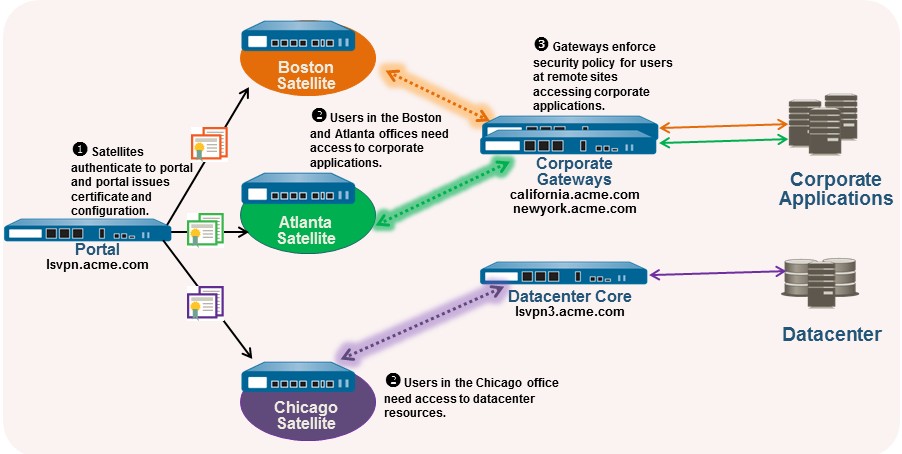
When a GlobalProtect satellite connects and successfully authenticates to the GlobalProtect portal, the portal delivers a satellite configuration, which specifies what gateways the satellite can connect to. If all your satellites will use the same gateway and certificate configurations, you can create a single satellite configuration to deliver to all satellites upon successful authentication. However, if you require different satellite configurations—for example if you want one group of satellites to connect to one gateway and another group of satellites to connect to a different gateway—you can create a separate satellite configuration for each. The portal will then use the enrollment username/group name or the serial number of the satellite to determine which satellite configuration to deploy. As with security rule evaluation, the portal looks for a match starting from the top of the list. When it finds a match, it delivers the corresponding configuration to the satellite.
For example, the following figure shows a network in which some branch offices require VPN access to the corporate applications protected by your perimeter firewalls and another site needs VPN access to the data center.
Use the following procedure to create one or more satellite configurations.
STEP 1 | Add a satellite configuration.
The satellite configuration specifies the GlobalProtect LSVPN configuration settings to deploy to the connecting satellites. You must define at least one satellite configuration.
-
Select Network > GlobalProtect > Portals and select the portal configuration for which you want to add a satellite configuration and then select the Satellite tab.
-
In the Satellite section, click Add .
-
Enter a Name for the configuration.
If you plan to create multiple configurations, make sure that the name you define for each is descriptive enough to allow you to distinguish them.
-
To change how often a satellite should check the portal for configuration updates, specify a value in the Configuration Refresh Interval (hours) field (range is 1-48; default is 24).
STEP 2 | Specify the satellites to which to deploy this configuration.
Portal matches Satellites to configurations based on Enrollment User/Group or Device Serial Numbers. Order matters: more specific configurations must precede general ones.
Specify the match criteria for the satellite configuration as follows:
-
Select the Devices tab, click Add , and enter serial number (you don’t need to enter the satellite hostname; it will be automatically added when the satellite connects) to restrict this configuration to satellites with specific serial numbers. Repeat this step for each satellite that you want to receive this configuration.
-
Select the Enrollment User/User Group tab, click Add , and then select the user or group you want to receive this configuration. Satellites that don’t match on serial number will be required to authenticate as a user specified here (either an individual user or group member).
STEP 3 | Specify the gateways that satellites with this configuration can establish VPN tunnels with.
Routes published by the gateway are installed on the satellite as static routes. The metric for the static route is 10x the routing priority. Ensure routing priorities are set correctly if using multiple gateways to control preference.
-
On the Gateways tab, click Add .
-
Enter a descriptive Name for the gateway. The name you enter here should match the name you defined when you configured the gateway and should be descriptive enough identify the location of the gateway.
-
Enter the FQDN or IP address of the interface where the gateway is configured in the Gateways field. The address you specify must exactly match the Common Name (CN) in the gateway server certificate.
-
(Optional) If you’re adding two or more gateways to the configuration, the Routing Priority helps the satellite pick the preferred gateway. Enter a value in the range of 1-25, with lower numbers having the higher priority (that is, the gateway the satellite will connect to if all gateways are available). The satellite will multiply the routing priority by 10 to determine the routing metric.
STEP 4 | Save the satellite configuration.
-
Click OK to save the satellite configuration.
-
If you want to add another satellite configuration, repeat the previous steps.
STEP 5 | Arrange the satellite configurations so that the proper configuration is deployed to each satellite.
-
To move a satellite configuration up on the list of configurations, select the configuration and click Move Up .
-
To move a satellite configuration down on the list of configurations, select the configuration and click Move Down .
STEP 6 | Specify the certificates required to enable satellites to participate in the LSVPN.
-
In the Trusted Root CA field, click Add and then select the CA certificate used to issue the gateway server certificates. The portal will deploy the root CA certificate you add here to all satellites as part of the configuration to enable the satellite to establish an SSL connection with the gateways. As a best practice, all of your gateways should use the same issuer.
-
Select the method of Client Certificate distribution:
-
To store the client certificates on the portal —select Local and select the root CA certificate that the portal will use to issue client certificates to satellites upon successfully authenticating them from the Issuing Certificate drop-down.
-
-
To enable the portal to act as a SCEP client to request dynamically and issue client certificates —select SCEP and then select the SCEP profile used to generate CSRs to your SCEP server.
STEP 7 | Save the portal configuration.
-
Click OK to save the settings and close the GlobalProtect portal configuration dialog.
-
Commit your changes.
Prepare the Satellite to Join the LSVPN
To participate in the LSVPN, the satellites require a minimal amount of configuration. Because the required configuration is minimal, you can pre-configure the satellites before shipping them to your branch offices for installation.
STEP 1 | Configure a Layer 3 Interface.
This is the physical interface that the satellite will use to connect to the portal and the gateway. This interface must be in a zone that allows access outside of the local trust network. As a best practice, create a dedicated zone for VPN connections for visibility and control over traffic destined for the corporate gateways.
STEP 2 | Configure the logical tunnel interface for the tunnel to use to establish VPN tunnels with the GlobalProtect gateways.
-
Select Network > Interfaces > Tunnel and click Add .
-
In the Interface Name field, specify a numeric suffix, such as .2 .
-
On the Config tab, expand the Security Zone drop-down and select an existing zone or create a separate zone for VPN tunnel traffic by clicking New Zone and defining a Name for the new zone (for example lsvpnsat ).
-
In the Virtual Router drop-down, select default .
-
(Optional) To assign an IP address to the tunnel interface:
-
For an IPv4 address, select IPv4 and Add the IP address and network mask to assign to the interface, for example 203.0.11.100/24.
-
For an IPv6 address, select IPv6 , Enable IPv6 on the interface , and Add the IP address and network mask to assign to the interface, for example 2001:1890:12f2:11::10.1.8.160/80.
-
-
To save the interface configuration, click OK .
STEP 3 | If you generated the portal server certificate using a root CA that isn’t trusted by the satellites (for example, if you used self-signed certificates), import the root CA certificate used to issue the portal server certificate.
This step is crucial for initial Satellite-to-Portal communication. The Satellite must trust the Portal's server certificate.
The root CA certificate is required to enable the satellite to establish the initial connection with the portal to obtain the LSVPN configuration.
-
Download the CA certificate that was used to generate the portal server certificates. If you’re using self-signed certificates, export the root CA certificate from the portal as follows:
-
Select Device > Certificate Management > Certificates , then Device Certificates .
-
Select the CA certificate, and click Export .
-
Select Base64 Encoded Certificate (PEM) from the File Format drop-down and click OK to download the certificate. (You don’t need to export the private key.)
-
-
Import the root CA certificate that you exported onto each satellite as follows.
-
Select Device > Certificate Management > Certificates , then Device Certificates . Select Import .
-
Enter a Certificate Name that identifies the certificate as your client CA certificate.
-
Browse to the Certificate File that you downloaded from the CA.
-
Select Base64 Encoded Certificate (PEM) as the File Format and then click OK .
-
Select the certificate that you imported on the Device Certificates tab to open it.
-
Select Trusted Root CA and then click OK .
-
STEP 4 | Configure the IPSec tunnel configuration.
-
Select Network > IPSec Tunnels and click Add .
-
On the General tab, enter a descriptive Name for the IPSec configuration.
-
Select the Tunnel Interface that you created for the satellite.
-
Select GlobalProtect Satellite as the Type .
-
Enter the IP address or FQDN of the portal as the Portal Address .
-
Select the Layer 3 Interface you configured for the satellite.
-
Select the IP Address to use on the selected interface. You can select an IPv4 address, an IPv6 address, or both. Specify if you want IPv6 preferred for portal registration .
STEP 5 | (Optional) Configure the satellite to publish local routes to the gateway.
Pushing routes to the gateway enables traffic to the subnets local to the satellite via the gateway. However, you must also configure the gateway to accept the routes as detailed in Configure GlobalProtect Gateways for LSVPN.
-
To enable the satellite to push routes to the gateway, on the Advanced tab select Publish all static and connected routes to Gateway .
If you select this check box, the firewall will forward all static and connected routes from the satellite to the gateway. However, to prevent the creation of routing loops, the firewall will apply some route filters, such as the following:
-
Default routes
-
Routes within a virtual router other than the virtual router associated with the tunnel interface
-
Routes using the tunnel interface
-
Routes using the physical interface associated with the tunnel interface
-
-
(Optional) If you only want to push routes for specific subnets rather than all routes, click Add in the Subnet section and specify which subnet routes to publish.
STEP 6 | Save the satellite configuration.
-
Click OK to save the IPSec tunnel settings.
-
Click Commit .
STEP 7 | If required, provide the credentials to allow the satellite to authenticate to the portal.
To authenticate to the portal for the first time, the satellite administrator must provide the username and password associated with the satellite admin account in the local database.
-
Select Network > IPSec Tunnels and click the Gateway Info link in the Status column of the tunnel configuration you created for the LSVPN.
-
Click the enter credentials link in the Portal Status field and provide the username and password to authenticate the satellite to the portal.
After the portal successfully authenticates to the portal, it will receive its signed certificate and configuration, which it will use to connect to the gateway(s). You should see that the tunnel is established and the Status is changed to Active .
Verify the LSVPN Configuration
After configuring the portal, gateways, and satellites, verify that the satellites are able to connect to the portal and gateway and establish VPN tunnels with one or more gateways.
STEP 1 | Verify satellite connectivity with portal.
From the firewall hosting the portal, verify that the satellites are successfully connecting by selecting Network > GlobalProtect > Portal and clicking Satellite Info in the Info column of the portal configuration entry.
STEP 2 | Verify satellite connectivity with the gateway(s).
On each firewall hosting a gateway, verify that satellites are able to establish VPN tunnels by selecting Network > GlobalProtect > Gateways and click Satellite Info in the Info column of the gateway configuration entry. Satellites that have successfully established tunnels with the gateway will display on the Active Satellites tab.
STEP 3 | Verify LSVPN tunnel status on the satellite.
On each firewall hosting a satellite, verify the tunnel status by selecting Network > IPSec Tunnels and verify active Status as indicated by a green icon.
Key verification points for LSVPN:
- Portal: Check Satellite Info (Network > GlobalProtect > Portal).
- Gateway: Check Satellite Info for active tunnels (Network > GlobalProtect > Gateways).
- Satellite: Check IPSec Tunnel status (Network > IPSec Tunnels).
- Logs: System, GlobalProtect, and VPN logs are invaluable for troubleshooting.
LSVPN Quick Configs
The following sections provide step-by-step instructions for configuring some common GlobalProtect LSVPN deployments:
-
Basic LSVPN Configuration with Static Routing
-
Advanced LSVPN Configuration with Dynamic Routing
-
Advanced LSVPN Configuration with iBGP
Basic LSVPN Configuration with Static Routing
This quick configuration shows the fastest way to get up and running with LSVPN. In this example, a single firewall at the corporate headquarters site is configured as both a portal and a gateway. Satellites can be quickly and easily deployed with minimal configuration for optimized scalability.
The following workflow shows the steps for setting up this basic configuration:
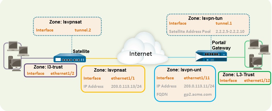
STEP 1 | Configure a Layer 3 interface.
In this example, the Layer 3 interface on the portal/gateway requires the following configuration:
-
Interface —ethernet1/11
-
Security Zone —lsvpn-tun
-
IPv4 —203.0.113.11/24
STEP 2 | On the firewall(s) hosting GlobalProtect gateway(s), configure the logical tunnel interface that will terminate VPN tunnels established by the GlobalProtect satellites.
In this example, the Tunnel interface on the portal/gateway requires the following configuration:
-
Interface —tunnel.1
-
Security Zone —lsvpn-tun
STEP 3 | Create the Security policy rule to enable traffic flow between the VPN zone where the tunnel terminates (lsvpn-tun) and the trust zone where the corporate applications reside (L3Trust).
STEP 4 | Assign an SSL/TLS Service profile to the portal/gateway. The profile must reference a selfsigned server certificate.
The certificate subject name must match the FQDN or IP address of the Layer 3 interface you create for the portal/gateway.
-
On the firewall hosting the GlobalProtect portal, create the root CA certificate for signing the certificates of the GlobalProtect components. In this example, the root CA certificate, lsvpn-CA , will be used to issue the server certificate for the portal/gateway.
In addition, the portal will use this root CA certificate to sign the CSRs from the satellites.
-
Create SSL/TLS service profiles for the GlobalProtect portal and gateways.
Because the portal and gateway are on the same interface in this example, they can share an SSL/TLS Service profile that uses the same server certificate. In this example, the profile is named lsvpnserver .
STEP 5 | Create a certificate profile.
In this example, the Certificate Profile lsvpn-profile references the root CA certificate lsvpn-CA . The gateway will use this Certificate Profile to authenticate satellites attempting to establish VPN tunnels.
STEP 6 | Configure the portal to authenticate satellites using local database authentication.
STEP 7 | Configure GlobalProtect Gateways for LSVPN.
Select Network > GlobalProtect > Gateways and Add a configuration. This example requires the following gateway configuration:
-
Interface —ethernet1/11
-
IP Address —203.0.113.11/24
-
SSL/TLS Server Profile —lsvpnserver
-
Certificate Profile —lsvpn-profile
-
Tunnel Interface —tunnel.1
-
Primary DNS / Secondary DNS —4.2.2.1/4.2.2.2
-
IP Pool —2.2.2.111-2.2.2.120
-
Access Route —10.2.10.0/24
STEP 8 | Configure the Portal.
Select Network > GlobalProtect > Portal and Add a configuration. This example requires the following portal configuration:
-
Interface —ethernet1/11
-
IP Address —203.0.113.11/24
-
SSL/TLS Server Profile —lsvpnserver
-
Authentication Profile —lsvpn-sat
STEP 9 | Define the Satellite Configurations.
On the Satellite tab in the portal configuration, Add a Satellite configuration and a Trusted root CA and specify the CA the portal will use to issue certificates for the satellites. In this example, the required settings are as following:
-
Gateway —203.0.113.11
-
Issuing Certificate —lsvpn-CA
-
Trusted Root CA —lsvpn-CA
STEP 10 | Prepare the Satellite to Join the LSVPN.
The satellite configuration in this example requires the following settings:
Interface configuration
-
Layer 3 interface—ethernet1/1, 203.0.113.13/24
-
Tunnel interface—tunnel.2
-
Zone—lsvpnsat
Root CA Certificate from Portal
-
lsvpn-CA
IPSec Tunnel configuration
-
Tunnel Interface —tunnel.2
-
Portal Address —203.0.113.11
-
Interface —ethernet1/1
-
Local IP Address —203.0.113.13/24
-
Publish all static and connected routes to Gateway —enabled
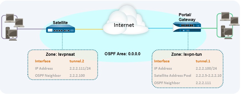
Advanced LSVPN Configuration with Dynamic Routing
In larger LSVPN deployments with multiple gateways and many satellites, investing a little more time in the initial configuration to set up dynamic routing will simplify the maintenance of gateway configurations because access routes will update dynamically. The following example configuration shows how to extend the basic LSVPN configuration to configure OSPF as the dynamic routing protocol.
Setting up an LSVPN to use OSPF for dynamic routing requires the following additional steps on the gateways and the satellites:
-
Manual assignment of IP addresses to tunnel interfaces on all gateways and satellites.
-
Configuration of OSPF point-to-multipoint (P2MP) on the virtual router on all gateways and satellites. In addition, as part of the OSPF configuration on each gateway, you must manually define the tunnel IP address of each satellite as an OSPF neighbor. Similarly, on each satellite, you must manually define the tunnel IP address of each gateway as an OSPF neighbor.
Although dynamic routing requires additional setup during the initial configuration of the LSVPN, it reduces the maintenance tasks associated with keeping routes up to date as topology changes occur on your network.
The following figure shows an LSVPN dynamic routing configuration. This example shows how to configure OSPF as the dynamic routing protocol for the VPN.
For a basic setup of a LSVPN, follow the steps in Basic LSVPN Configuration with Static Routing. You can then complete the steps in the following workflow to extend the configuration to use dynamic routing rather than static routing.
STEP 1 | Add an IP address to the tunnel interface configuration on each gateway and each satellite.
Complete the following steps on each gateway and each satellite:
-
Select Network > Interfaces > Tunnel and select the tunnel configuration you created for the LSVPN to open the Tunnel Interface dialog.
If you haven’t yet created the tunnel interface, see step 2 in Create Interfaces and Zones for the LSVPN.
-
On the IPv4 tab, click Add and then enter an IP address and subnet mask. For example, to add an IP address for the gateway tunnel interface you would enter 2.2.2.100/24.
-
Click OK to save the configuration.
STEP 2 | Configure the dynamic routing protocol on the gateway.
To configure OSPF on the gateway:
-
Select Network > Virtual Routers and select the virtual router associated with your VPN interfaces.
-
On the Areas tab, click Add to create the backbone area, or, if it’s already configured, click on the area ID to edit it.
-
If you’re creating a new area, enter an Area ID on the Type tab.
-
On the Interface tab, click Add and select the tunnel Interface you created for the LSVPN.
-
Select p2mp as the Link Type .
-
Click Add in the Neighbors section and enter the IP address of the tunnel interface of each satellite, for example 2.2.2.111.
-
Click OK twice to save the virtual router configuration and then Commit the changes on the gateway.
-
Repeat this step each time you add a new satellite to the LSVPN.
STEP 3 | Configure the dynamic routing protocol on the satellite.
To configure OSPF on the satellite:
-
Select Network > Virtual Routers and select the virtual router associated with your VPN interfaces.
-
On the Areas tab, click Add to create the backbone area, or, if it’s already configured, click on the area ID to edit it.
-
If you’re creating a new area, enter an Area ID on the Type tab.
-
On the Interface tab, click Add and select the tunnel Interface you created for the LSVPN.
-
Select p2mp as the Link Type .
-
Click Add in the Neighbors section and enter the IP address of the tunnel interface of each GlobalProtect gateway, for example 2.2.2.100.
-
Click OK twice to save the virtual router configuration and then Commit the changes on the gateway.
-
Repeat this step each time you add a new gateway.
STEP 4 | Verify that the gateways and satellites are able to form router adjacencies.
-
On each satellite and each gateway, confirm that peer adjacencies have formed and that routing table entries have been created for the peers (that is, the satellites have routes to the gateways and the gateways have routes to the satellites). Select Network > Virtual Router and click the More Runtime Stats link for the virtual router you’re using for the LSVPN. On the Routing tab, verify that the LSVPN peer has a route.
-
On the OSPF > Interface tab, verify that the Type is p2mp .
-
On the OSPF > Neighbor tab, verify that the firewalls hosting your gateways have established router adjacencies with the firewalls hosting your satellites and vice versa. Also verify that the Status is Full , indicating that full adjacencies have been established.
Advanced LSVPN Configuration with iBGP
This use case illustrates how GlobalProtect LSVPN securely connects distributed office locations with primary and disaster recovery data centers that house critical applications for users and how an internal border gateway protocol (iBGP) eases deployment and upkeep. Using this method, you can extend up to 500 satellite offices connecting to a single gateway.
BGP is a highly scalable, dynamic routing protocol that is ideal for hub-and-spoke deployments such as LSVPN. As a dynamic routing protocol, it eliminates much of the overhead associated with access routes (static routes) by making it relatively easy to deploy additional satellite firewalls. Due to its route filtering capabilities and features such as multiple tunable timers, route dampening, and route refresh, BGP scales to a higher number of routing prefixes with greater stability than other routing protocols like RIP and OSPF. In the case of iBGP, a peer group, which includes all the satellites and gateways in the LSVPN deployment, establishes adjacencies over the tunnel endpoints. The protocol then implicitly takes control of route advertisements, updates, and convergence.
In this example configuration, an active/passive HA pair of PA-5200 firewalls is deployed in the primary (active) data center and acts as the portal and primary gateway. The disaster recovery data center also has two PA-5200s in an active/passive HA pair acting as the backup LSVPN gateway. The portal and gateways serve 500 PA-220s deployed as LSVPN satellites in branch offices.
Both data center sites advertise routes but with different metrics. As a result, the satellites prefer and install the active data center’s routes. However, the backup routes also exist in the local routing information base (RIB). If the active data center fails, the routes advertised by that data center are removed and replaced with routes from the disaster recovery data center’s routes. The failover time depends on selection of iBGP times and routing convergence associated with iBGP.
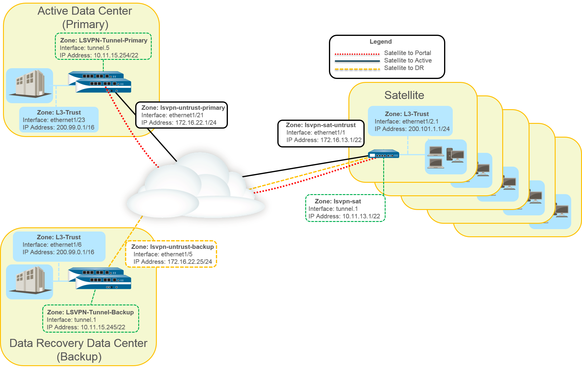
The following workflow shows the steps for configuring this deployment:
STEP 1 | Create Interfaces and Zones for the LSVPN.
Portal and primary gateway:
-
Zone : LSVPN-Untrust-Primary
-
Interface: ethernet1/21
-
IPv4: 172.16.22.1/24
-
Zone : L3-Trust
-
Interface : ethernet1/23
-
IPv4 : 200.99.0.1/16 Backup gateway:
-
Zone : LSVPN-Untrust-Primary
-
Interface : ethernet1/5
-
IPv4 : 172.16.22.25/24
-
Zone : L3-Trust
-
Interface : ethernet1/6
-
IPv4 : 200.99.0.1/16
Satellite:
-
Zone : LSVPN-Sat-Untrust
-
Interface : ethernet1/1
-
IPv4 : 172.16.13.1/22
-
Zone : L3-Trust
-
Interface : ethernet1/2.1
-
IPv4 : 200.101.1.1/24
STEP 2 | On the firewall(s) hosting GlobalProtect gateway(s), configure the logical tunnel interface that will terminate VPN tunnels established by the GlobalProtect satellites.
Primary gateway :
-
Interface : tunnel.5
-
IPv4 : 10.11.15.254/22 • Zone : LSVPN-Tunnel-Primary Backup gateway :
-
Interface : tunnel.1
-
IPv4 : 10.11.15.245/22
-
Zone : LSVPN-Tunnel-Backup
STEP 3 | Enable SSL Between GlobalProtect LSVPN Components.
The gateway uses the self-signed root certificate authority (CA) to issue certificates for the satellites in a GlobalProtect LSVPN. Because one firewall houses the portal and primary gateway, a single certificate is used for authenticating to the satellites. The same CA is used to generate a certificate for the backup gateway. The CA generates certificates that pushed to the satellites from the portal and then used by the satellites to authenticate to the gateways.
You must also generate a certificate from the same CA for the backup gateway, allowing it to authenticate with the satellites.
-
On the firewall hosting the GlobalProtect portal, create the root CA certificate for signing the certificates of the GlobalProtect components. In this example, the root CA certificate is called CA-cert.
-
Create SSL/TLS service profiles for the GlobalProtect portal and gateways. Because the GlobalProtect portal and primary gateway are the same firewall interface, you can use the same server certificate for both components.
-
Root CA Certificate : CA-Cert
-
Certificate Name : LSVPN-Scale
-
-
Deploy the self-signed server certificates to the gateways.
-
Import the root CA certificate used to issue server certificates for the LSVPN components.
-
Create a certificate profile.
-
Repeat steps 2 through 5 on the backup gateway with the following settings:
-
Root CA Certificate : CA-cert
-
Certificate Name : LSVPN-back-GW-cert
-
STEP 4 | Configure GlobalProtect Gateways for LSVPN.
-
Select Network > GlobalProtect > Gateways and click Add .
-
On the General tab, name the primary gateway LSVPN-Scale .
-
Under Network Settings , select ethernet1/21 as the primary gateway interface and enter 172.16.22.1/24 as the IP address.
-
On the Authentication tab, select the LSVPN-Scale certificate created in 3.
-
Select Satellite > Tunnel Settings and select Tunnel Configuration . Set the Tunnel
Interface to tunnel.5. All satellites in this use case connect to a single gateway, so a
single satellite configuration is needed. Satellites are matched based on their serial numbers, so no satellites will need to authenticate as a user.
-
On Satellite > Network Settings , define the pool of IP address to assign to the tunnel interface on the satellite once the VPN connection is established. Because this use case uses dynamic routing, the Access Routes setting remains blank.
-
Repeat steps 1 through 5 on the backup gateway with the following settings:
-
Name : LSVPN-backup
-
Gateway interface : ethernet1/5
-
Gateway IP : 172.16.22.25/24
-
Server cert : LSVPN-backup-GW-cert
-
Tunnel interface : tunnel.1
-
STEP 5 | Configure iBGP on the primary and backup gateways and add a redistribution profile to allow the satellites to inject local routes back to the gateways.
Each satellite office manages its own network and firewall, so the redistribution profile called ToAllSat is configured to redistribute local routes back to the GlobalProtect gateway.
-
Select Network > Virtual Routers and Add a virtual router.
-
On Router Settings , add the Name and Interface for the virtual router.
-
On Redistribution Profile , select Add .
-
Name the redistribution profile ToAllSat and set the Priority to 1.
-
Set Redistribute to Redist .
-
Add ethernet1/23 from the Interface drop-down.
-
Click OK .
-
-
Select BGP on the virtual router to configure BGP.
-
On BGP > General , select Enable .
-
Enter the gateway IP address as the Router ID ( 172.16.22.1 ) and 1000 as the AS Number .
-
In the Options section, select Install Route .
-
On BGP > Peer Group , click Add a peer group with all the satellites that will connect to the gateway.
-
On BGP > Redist Rules , Add the ToAllSat redistribution profile you created previously.
-
-
Click OK .
-
Repeat steps 1 through 5 on the backup gateway using ethernet1/6 for the redistribution profile.
STEP 6 | Prepare the Satellite to Join the LSVPN.
The configuration shown is a sample of a single satellite.
Repeat this configuration each time you add a new satellite to the LSVPN deployment.
-
Configure a tunnel interface as the tunnel endpoint for the VPN connection to the gateways.
-
Set the IPSec tunnel type to GlobalProtect Satellite and enter the IP address of the GlobalProtect portal.
-
Select Network > Virtual Routers and Add a virtual router.
-
On Router Settings , add the Name and Interface for the virtual router.
-
Select Virtual Router > Redistribution Profile and Add a profile with the following settings.
-
Name the redistribution profile ToLSVPNGW and set the Priority to 1.
-
Add an Interface ethernet1/2.1 .
-
Click OK .
-
-
Select BGP > General , Enable BGP and configure the protocol as follows:
-
Enter the gateway IP address as the Router ID ( 172.16.22.1 ) and 1000 as the AS Number .
-
In the Options section, select Install Route .
-
On BGP > Peer Group , Add a peer group containing all the satellites that will connect to the gateway.
-
On BGP > Redist Rules , Add the ToLSVPNGW redistribution profile you created previously.
-
-
Click OK .
STEP 7 | Configure the GlobalProtect Portal for LSVPN.
Both data centers advertise their routes but with different routing priorities to ensure that the active data center is the preferred gateway.
-
Select Network > GlobalProtect > Portals and click Add .
-
On General , enter LSVPN-Portal as the portal name.
-
On Network Settings , select ethernet1/21 as the Interface and select 172.16.22.1/24 as the IP Address .
-
On the Authentication tab, select the previously created primary gateway SSL/TLS Profile LSVPN-Scale from the SSL/TLS Service Profile drop-down.
-
On the Satellite tab, Add a satellite and Name it sat-config-1 .
-
Set the Configuration Refresh Interval to 12 .
-
On GlobalProtect Satellite > Devices , add the serial number and hostname of each satellite device in the LSVPN.
-
On GlobalProtect Satellite > Gateways , add the name and IP address of each gateway. Set the routing priority of the primary gateway to 1 and the backup gateway to 10 to ensure that the active data center is the preferred gateway.
STEP 8 | Verify the LSVPN Configuration.
STEP 9 | (Optional) Add a new site to the LSVPN deployment.
-
Select Network > GlobalProtect > Portals > GlobalProtect Portal > Satellite
Configuration > GlobalProtect Satellite > Devices to add the serial number of the new satellite to the GlobalProtect portal.
-
Configure the IPSec tunnel on the satellite with the GlobalProtect portal IP address.
-
Select Network > Virtual Router > BGP > Peer Group to add the satellite to the BGP peer group configuration on each gateway.
-
Select Network > Virtual Router > BGP > Peer Group to add the gateways to the BGP peer group configuration on the new satellite.
Key LSVPN Concepts for PCNSE
Understanding these LSVPN aspects is crucial for the PCNSE exam:
-
LSVPN Components: Know the roles of the Portal, Gateway, and Satellite.
- Portal: Central management, pushes configuration and certificates to Satellites.
- Gateway: Hub device, terminates IPSec tunnels, provides access to protected resources.
- Satellite: Remote site firewall, initiates tunnels to Gateways.
-
Licensing: LSVPN itself does not require a GlobalProtect subscription.
-
Certificates: LSVPN relies heavily on certificates for authentication.
- Portal needs a server certificate.
- Gateways need server certificates.
- Satellites receive their server certificates and client certificates (for authenticating to Gateways) from the Portal.
- A common Root CA (either enterprise or self-signed on the Portal) should issue/be trusted by all components.
- SSL/TLS Service Profiles are used on Portals and Gateways.
- Certificate Profiles are used for validating peer certificates.
-
Satellite Authentication to Portal:
- PAN-OS 10.0 and earlier: Primarily Serial Number based.
- PAN-OS 10.1+: Default is Username/Password (local DB on Portal) for initial connection, then a Satellite Cookie for subsequent authentications. Cookie lifetime is important.
- PAN-OS 11.1.3+: Adds Serial Number + IP Address authentication.
-
Tunnel Interface on Gateway: A single tunnel interface on a Gateway can serve multiple Satellites (point-to-multipoint).
-
Routing:
- Static: Access Routes configured on the Gateway are pushed to Satellites. Satellites can publish their local routes back.
- Dynamic (OSPF, BGP): Requires IP addresses on tunnel interfaces. OSPF often uses P2MP network type. BGP (iBGP) is highly scalable.
-
Configuration Flow: Portal pushes Gateway list, certificates, IP pool info, and access routes to Satellites.
-
Tunnel Monitoring: Supported for failover to backup Gateways.
Focus on the distinct roles of Portal vs. Gateway, certificate management (especially the Root CA and what components need which certs), Satellite authentication mechanisms (initial vs. cookie), and routing options (static vs. dynamic implications).
LSVPN Operational Diagrams
LSVPN Component Interaction
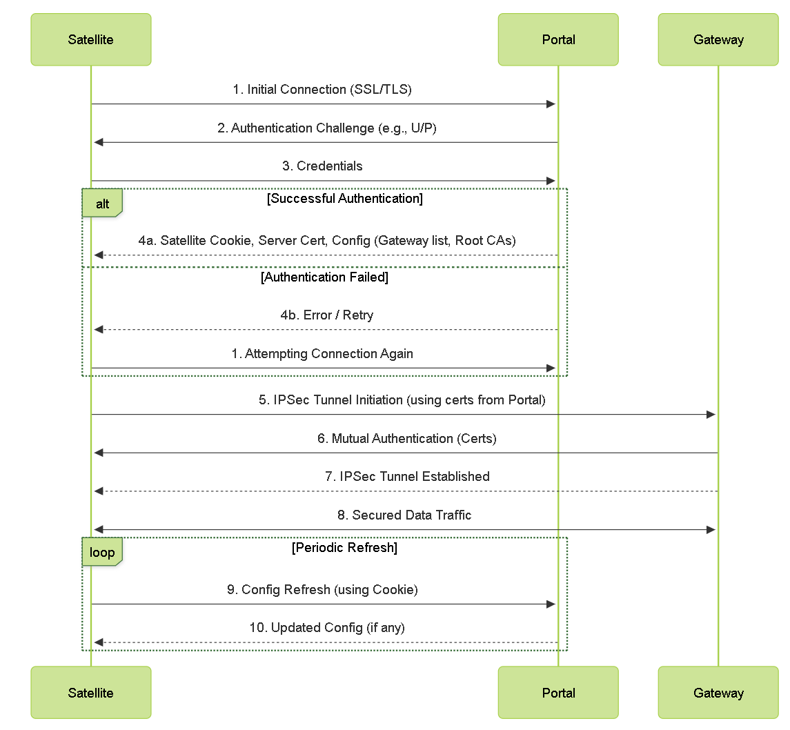
Detailed LSVPN component interaction and authentication flow.
LSVPN Certificate Management Overview
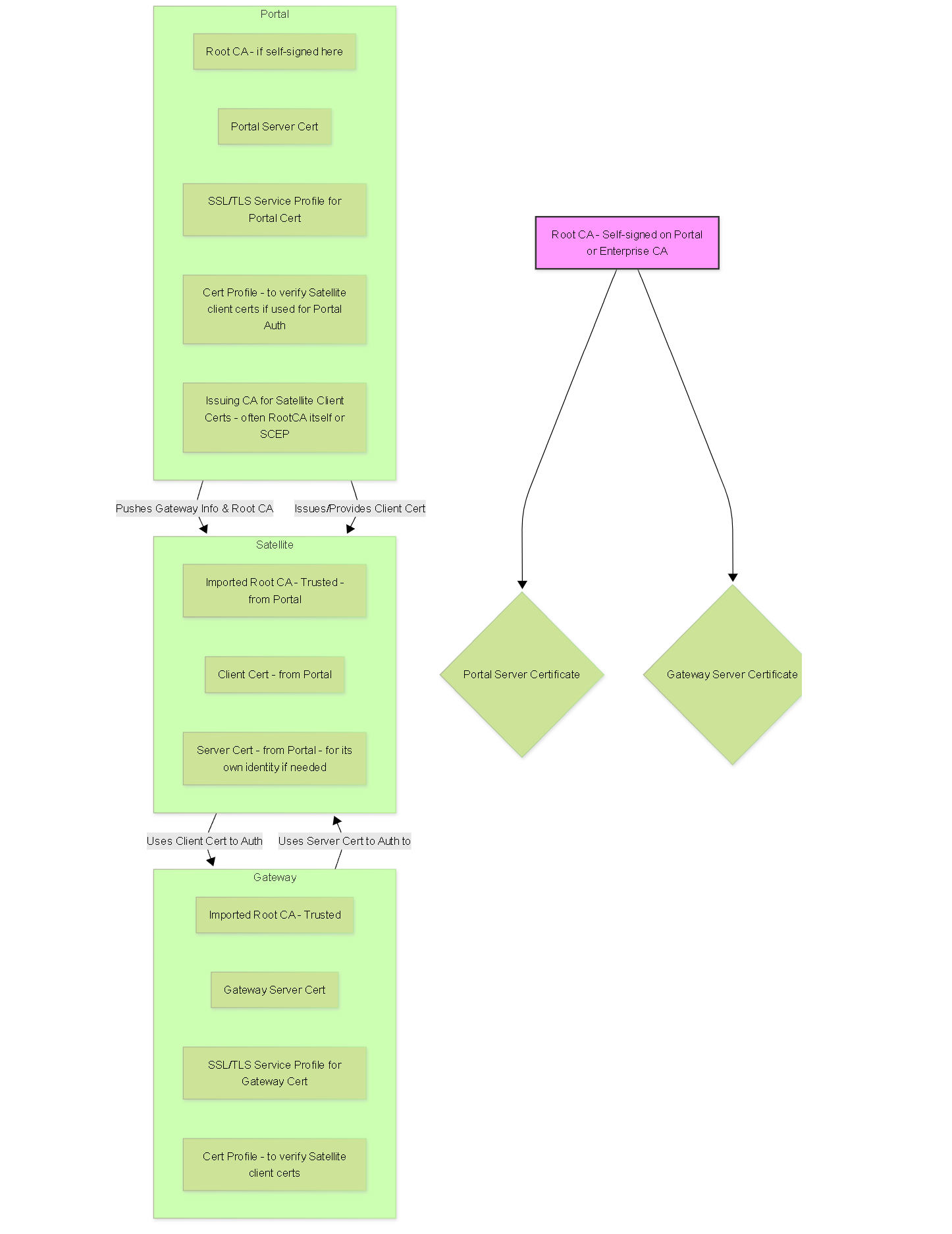
Conceptual overview of certificate roles and trust in LSVPN.
Common LSVPN Gotchas for PCNSE
-
Certificate Mismatches:
- CN/SAN on Gateway server certificate not matching the address configured on the Portal for that Gateway.
- Root CA that signed Portal/Gateway server certificates not imported and trusted on Satellites (for Portal) or Gateways/Satellites (for Gateway connections).
- Expired certificates.
-
Satellite Authentication Failures:
- Incorrect username/password for initial Portal authentication (if using U/P + Cookie method).
- Satellite serial number not correctly entered in the Portal configuration (if using serial number based auth).
- Satellite cookie expired, requiring manual re-authentication by an administrator on the Satellite.
- Incorrect Authentication Profile or Certificate Profile selected in the Portal/Gateway configuration.
-
Routing Issues:
- IP address not assigned to tunnel interfaces when using dynamic routing protocols (OSPF, BGP).
- Incorrect Access Routes on Gateway, or routes not being published/accepted correctly between Satellite and Gateway.
- For dynamic routing, ensure routing protocols are correctly configured on both Gateway and Satellite virtual routers, including neighbor relationships and redistribution if needed. OSPF P2MP network type is common.
- Firewall policies blocking routing protocol traffic over the tunnel.
-
Zone Configuration:
- Portal/Gateway external interface not in a zone accessible by Satellites.
- Tunnel interface on Gateway not in an appropriate zone (e.g., a dedicated VPN zone or trust zone).
- Missing security policies to allow traffic between the VPN zone and internal/trusted zones.
- User-ID not enabled on the Gateway's tunnel termination zone, leading to lack of user visibility for VPN traffic.
-
Portal Configuration Order:
- If multiple Satellite Configurations are defined on the Portal, the order matters. The first match (by serial number or user/group) is used. More specific rules should be higher in the list.
-
Commits:
- Forgetting to commit configuration changes on Portal, Gateway, or Satellite after making modifications.
Troubleshooting LSVPN often involves checking certificates, authentication settings, routing tables, and security policies on all involved components (Portal, Gateway, Satellite). Pay close attention to logs (System, GlobalProtect, VPN).