GRE Fundamentals
What is GRE?
Generic Routing Encapsulation (GRE) is a tunneling protocol developed by Cisco Systems that can encapsulate a wide variety of network layer protocols inside virtual point-to-point links over an Internet Protocol network. Essentially, GRE creates a private pathway for data packets to travel between two points across an IP network, as if they were directly connected.
The primary function of GRE is to encapsulate a payload, which is an original packet with its own protocol (like IPv4, IPv6, AppleTalk, etc.), inside a new IP packet. This new IP packet uses GRE protocol for its payload and has its own IP header (the "outer" IP header) that routes it through the transit IP network to the tunnel endpoint. At the destination, the outer header and GRE header are removed, and the original packet is forwarded to its final destination.
Key Characteristic: GRE is defined by RFC 2784 and RFC 2890. It is considered a stateless protocol, meaning it doesn't maintain information about the state of the connection or flow control, relying on the encapsulated protocols for such mechanisms.
GRE itself does not provide any encryption or strong security mechanisms. While it has a basic mechanism for keying, the key is part of the GRE header and offers minimal protection. Therefore, if security is a concern, GRE is typically used in conjunction with other security protocols like IPSec.
GRE Use Cases
GRE tunnels are versatile and employed in various networking scenarios:
- Connecting Disjoint Networks: GRE can link subnets that are geographically separated or logically distinct, making them appear as a single contiguous network across an IP infrastructure.
- Transporting Multicast Traffic: Standard IPsec tunnels often do not support multicast traffic. GRE can encapsulate multicast packets, allowing them to be transported over unicast-only networks or through VPNs that would otherwise block them. This is crucial for applications like video conferencing or streaming services.
- Enabling Routing Protocols: GRE tunnels provide a virtual interface over which dynamic routing protocols (like OSPF, EIGRP, BGP, RIP) can operate. This allows routers to exchange routing information and dynamically learn routes across the tunnel, as if it were a physical link.
- VPNs where IPsec is not feasible or required: In situations where the overhead or complexity of IPsec is undesirable and strong encryption is not a primary concern, GRE can provide a simpler tunneling solution.
- Transporting Non-IP Protocols: GRE can encapsulate protocols other than IP, allowing them to be carried across an IP-only network.
- Bypassing Network Hop Limits: By encapsulating packets, GRE can effectively bypass limitations on the number of hops a packet can traverse in some networks.
- Steering Traffic to Security Services: GRE can be used to direct specific types of traffic (e.g., HTTP/HTTPS) to cloud-based security services like Netskope or Zscaler for inspection.
GRE Packet Structure & Overhead
A GRE-encapsulated packet consists of the original packet (payload) wrapped by a GRE header and then a new IP header (outer IP header).
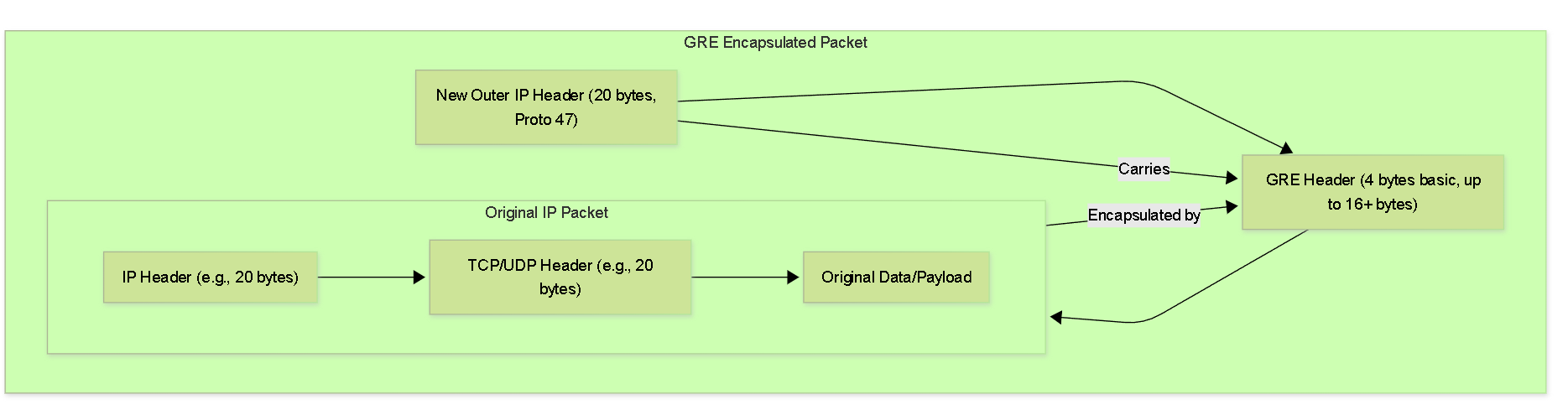
GRE Packet Encapsulation.
The components are:
- Original Packet (Payload): This is the actual data packet that needs to be tunneled. It has its own IP header (inner IP header) and transport layer header (e.g., TCP, UDP).
-
GRE Header:
This header is added by the GRE protocol.
- A basic GRE header is 4 bytes .
- The GRE header can be larger if optional fields like Key, Sequence Number, or Checksum are enabled (up to an additional 12 bytes or more). For PCNSE purposes, focus on the basic overhead unless specified.
-
New IP Header (Outer IP Header):
This is a standard IP header (typically
20 bytes
for IPv4) that is added to the GRE packet.
- The source IP address in this header is the IP address of the GRE tunnel entry point (e.g., the public IP of the sending firewall).
- The destination IP address is the IP address of the GRE tunnel exit point (e.g., the public IP of the receiving firewall).
- The protocol field in this outer IP header is set to 47 to indicate that the payload is a GRE packet.
Total GRE Overhead:
For a basic GRE tunnel (without optional GRE header fields), the overhead added to the original packet is typically:
24 bytes
= 4 bytes (GRE header) + 20 bytes (New Outer IP header).
This overhead is crucial when considering MTU (Maximum Transmission Unit) adjustments, which will be discussed later.
GRE over IPSec
Introduction to GRE over IPSec
While GRE provides excellent flexibility for tunneling various protocols and multicast traffic, it lacks inherent security features like encryption and robust authentication. This makes plain GRE unsuitable for transmitting sensitive data over untrusted networks like the internet.
To address this, GRE can be combined with IPSec. In a GRE over IPSec configuration, the GRE encapsulated packet (which contains the original data) is itself encapsulated and protected by IPSec. This leverages the flexibility of GRE with the strong security (confidentiality, integrity, and authentication) provided by IPSec.
The process involves two main layers of encapsulation:
- GRE Encapsulation: The original packet is first encapsulated by GRE, adding a GRE header and a new IP header (the "GRE IP header" or "inner IP header" from IPSec's perspective).
- IPSec Encapsulation: The resulting GRE packet is then treated as the payload for an IPSec tunnel. IPSec encrypts and/or authenticates this GRE packet, adding its own IPSec headers (e.g., ESP header) and another IP header (the "outer IP header").
Benefit: This combination allows secure transport of traffic that IPSec alone might not support (like multicast or certain routing protocols) or simplifies configurations for complex multi-protocol environments while ensuring data protection.
Use Cases for GRE over IPSec
Combining GRE with IPSec is particularly beneficial in scenarios where both the flexibility of GRE and the security of IPSec are required:
- Securely Transmitting Multicast Traffic: Standard IPSec tunnels typically do not support multicast traffic. By encapsulating multicast packets within GRE and then securing the GRE tunnel with IPSec, organizations can securely extend multicast applications (e.g., video conferencing, financial data feeds) across untrusted networks.
- Running Routing Protocols Securely: When dynamic routing protocols (OSPF, BGP, EIGRP, RIP) need to operate between sites connected over the internet, GRE provides the necessary multi-protocol transport. Adding IPSec ensures that the routing updates and the data traffic traversing the tunnel are protected from eavesdropping and tampering.
- Securely Encapsulating Non-IP Protocols: If legacy non-IP protocols need to be transported across an IP network, GRE can encapsulate them. IPSec then provides the security layer for these encapsulated packets.
- Building Resilient and Flexible VPNs: GRE over IPSec allows for the creation of routable tunnel interfaces, simplifying routing logic and enabling more complex and resilient network designs compared to some policy-based IPSec VPNs.
- Interoperability with Devices Requiring GRE for Certain Features: Some network environments or specific vendor implementations might require GRE for features like MPLS over IP or to connect to certain cloud services securely when multicast or specific routing capabilities are needed.
Scenario: Secure Branch Connectivity with Dynamic Routing
A company wants to connect its branch offices to its headquarters. They need to run OSPF between the sites for dynamic route exchange and also ensure all traffic, including sensitive internal application data, is encrypted.
Solution:
GRE over IPSec. GRE tunnels are established between the Palo Alto Networks firewalls at each site. OSPF adjacencies are formed over these GRE tunnels. The GRE tunnels are then secured by underlying IPSec tunnels, encrypting all OSPF updates and user data.
IPSec Fundamentals: IKE Phase 1
Internet Key Exchange (IKE) is the protocol used to negotiate, establish, and manage Security Associations (SAs) for IPSec. It operates in two distinct phases.
IKE Phase 1 (Main Mode or Aggressive Mode)
The primary purpose of IKE Phase 1 is to authenticate the IPSec peers and establish a secure, authenticated channel between them. This secure channel, often called the IKE SA or ISAKMP SA, is then used to protect the negotiations for IKE Phase 2.
Key objectives and parameters negotiated in IKE Phase 1 include:
-
Authentication Method:
How peers prove their identities. Common methods are:
- Pre-Shared Keys (PSK): A secret key manually configured on both peers. Simpler to set up but less scalable.
- Digital Certificates: Uses X.509 certificates for stronger, scalable authentication.
- Encryption Algorithm: To protect the IKE Phase 1 negotiation itself (e.g., AES, 3DES).
- Hashing Algorithm: For integrity checking of IKE messages (e.g., SHA1, SHA256, SHA384, SHA512).
- Diffie-Hellman (DH) Group: Used to securely establish a shared secret key for encrypting Phase 1 communications. Higher DH group numbers generally provide stronger keys (e.g., Group 14, 19, 20, 21 are common).
- Lifetime: How long the IKE SA remains valid before it needs to be re-negotiated (e.g., 8 hours or 28800 seconds).
- IKE Version: IKEv1 or IKEv2. IKEv2 is generally preferred for its improvements in efficiency, security, and reliability (e.g., built-in NAT traversal, EAP support).
Palo Alto Networks firewalls configure these parameters within an IKE Crypto Profile and an IKE Gateway object.
- IKE Crypto Profile: Defines the encryption, hash, DH group, and lifetime for Phase 1.
- IKE Gateway: Defines the peer's IP address, the local interface for the tunnel, the IKE version, authentication method (PSK or certificate), local and peer identification.
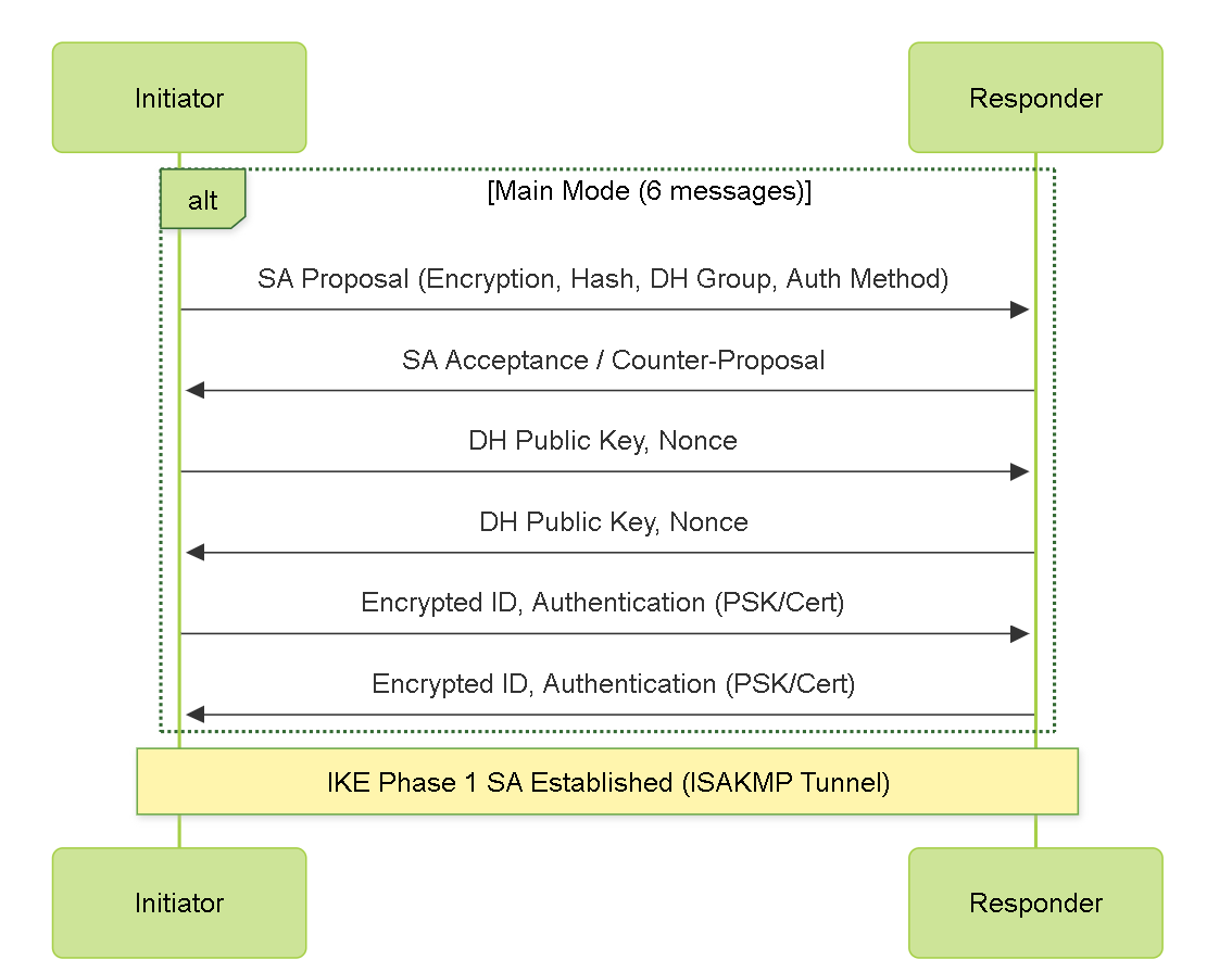
Simplified IKE Phase 1 (Main Mode) Negotiation.
IPSec Fundamentals: IKE Phase 2
Once IKE Phase 1 has successfully established a secure IKE SA (ISAKMP SA), IKE Phase 2 (often referred to as Quick Mode in IKEv1) begins. The negotiations in Phase 2 occur within the protection of the IKE Phase 1 tunnel.
The primary purpose of IKE Phase 2 is to negotiate the actual IPSec SAs (also known as Child SAs) that will be used to protect user data traffic. Multiple Phase 2 SAs can be established under a single Phase 1 SA.
Key parameters negotiated in IKE Phase 2 include:
-
IPSec Protocol:
Which security protocol will be used for the data.
- ESP (Encapsulating Security Payload): Provides confidentiality (encryption), integrity, authentication, and anti-replay protection. This is the most commonly used protocol.
- AH (Authentication Header): Provides integrity, authentication, and anti-replay protection, but NO encryption .
- Encryption Algorithm (if ESP is used): e.g., AES-128, AES-256, 3DES.
- Authentication/Integrity Algorithm: e.g., SHA1, SHA256, SHA384, SHA512.
-
Encapsulation Mode:
- Tunnel Mode: The original IP packet is fully encapsulated with a new outer IP header. This is typically used for site-to-site VPNs (gateway-to-gateway).
- Transport Mode: Only the IP payload (e.g., TCP/UDP segment) is protected. The original IP header is largely retained. Used when the IPSec endpoints are the actual source and destination of the traffic (host-to-host). For GRE over IPSec, IPSec is typically in Tunnel Mode protecting the GRE packet.
- Lifetime: How long the IPSec SA remains valid before re-keying (e.g., 1 hour or 3600 seconds, or by data volume).
- Perfect Forward Secrecy (PFS): (Optional but recommended) If enabled, a new Diffie-Hellman exchange is performed for each Phase 2 negotiation, ensuring that session keys derived for this SA are not compromised if the IKE Phase 1 key is compromised. Requires specifying a DH Group (e.g., Group 14, 19, 20, 21).
- Proxy IDs / Traffic Selectors: These define what traffic is allowed to be encrypted and sent through the IPSec tunnel. They specify source IP address(es)/subnet(s), destination IP address(es)/subnet(s), and protocol/port for the traffic to be protected. This is a critical component.
On Palo Alto Networks firewalls, Phase 2 parameters are configured in an IPSec Crypto Profile , and the Proxy IDs are configured within the IPSec Tunnel configuration.
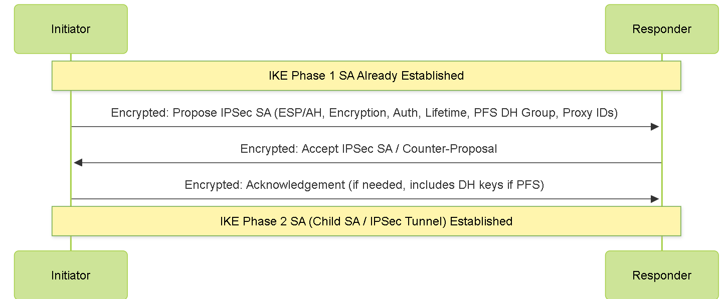
Simplified IKE Phase 2 (Quick Mode) Negotiation.
IPSec Fundamentals: AH vs ESP
IPSec provides two primary security protocols to protect data: Authentication Header (AH) and Encapsulating Security Payload (ESP).
Authentication Header (AH)
AH, defined in RFC 4302, provides the following services:
- Connectionless Integrity: Ensures that the data has not been altered in transit.
- Data Origin Authentication: Verifies the identity of the sender.
- Anti-Replay Protection: Prevents attackers from capturing and retransmitting packets.
AH authenticates the entire IP packet, including parts of the IP header that might change in transit (like TTL, TOS, Fragment Offset, Flags, Header Checksum if they are mutable). To handle this, AH treats these mutable fields as zero for checksum calculation. AH is IP protocol number 51.
Use Cases for AH:
- When confidentiality is not required, but strong authentication and integrity of the entire packet are paramount.
- Situations where encryption is handled by another layer or is prohibited.
AH is less commonly used today primarily because ESP can also provide authentication and integrity, along with the crucial addition of encryption.
Encapsulating Security Payload (ESP)
ESP, defined in RFC 4303, can provide a broader range of security services:
- Confidentiality (Encryption): Encrypts the payload of the IP packet, protecting it from eavesdropping.
- Connectionless Integrity (Optional but typically used): Ensures data has not been altered.
- Data Origin Authentication (Optional but typically used): Verifies the sender's identity.
- Anti-Replay Protection.
- Limited Traffic Flow Confidentiality (in Tunnel Mode): Hides the original source and destination of the traffic by creating new outer IP headers.
When ESP provides both encryption and authentication, it encrypts the IP payload first and then appends an integrity check value (ICV) for the encrypted payload and ESP header/trailer. ESP does not authenticate the outer IP header. ESP is IP protocol number 50.
Use Cases for ESP:
- The vast majority of VPN implementations, as it provides a comprehensive security solution.
- Any scenario where sensitive data needs to be protected during transmission.
For the PCNSE exam, understand the distinct services offered by AH and ESP. ESP is the predominant choice due to its encryption capabilities. Know that ESP can provide authentication and integrity, making AH redundant in many cases. If both are used, it adds complexity and overhead.
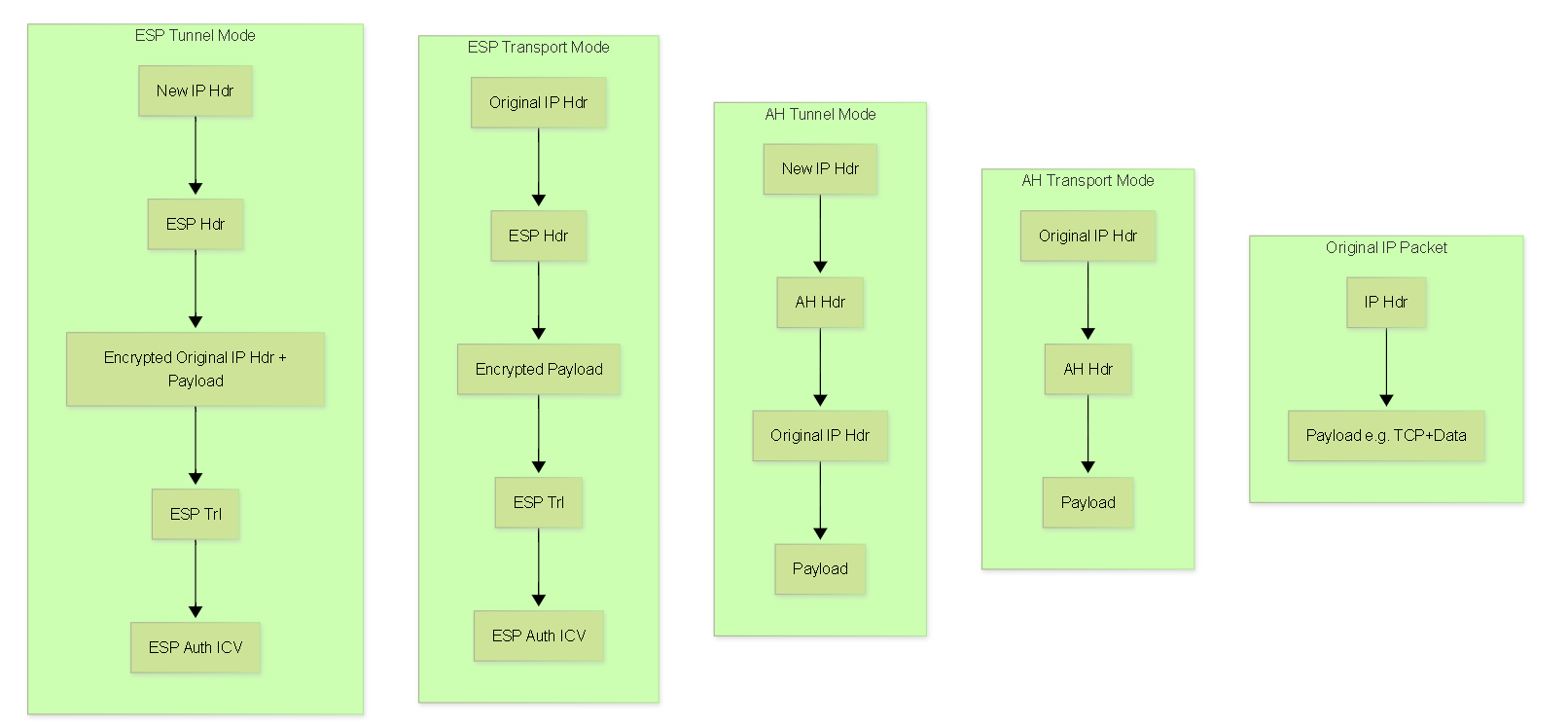
Simplified comparison of AH and ESP packet structures in Transport and Tunnel modes.
GRE over IPSec Packet Flow
Understanding the encapsulation order in GRE over IPSec is crucial. Here's how an original data packet is transformed:
-
Original Packet:
[Original IP Header | Original TCP/UDP Header | Data] -
After GRE Encapsulation:
The original packet becomes the payload for GRE.
[New IP Header (GRE Endpoints, Proto 47) | GRE Header | [Original IP Header | Original TCP/UDP Header | Data]] -
After IPSec Encapsulation (using ESP in Tunnel Mode):
The entire GRE packet becomes the payload for IPSec.
[Outer IP Header (IPSec Endpoints, Proto 50) | ESP Header | [Encrypted: [New IP Header (GRE Endpoints) | GRE Header | [Original IP Header | Original TCP/UDP Header | Data]]] | ESP Trailer | ESP Auth (ICV)]
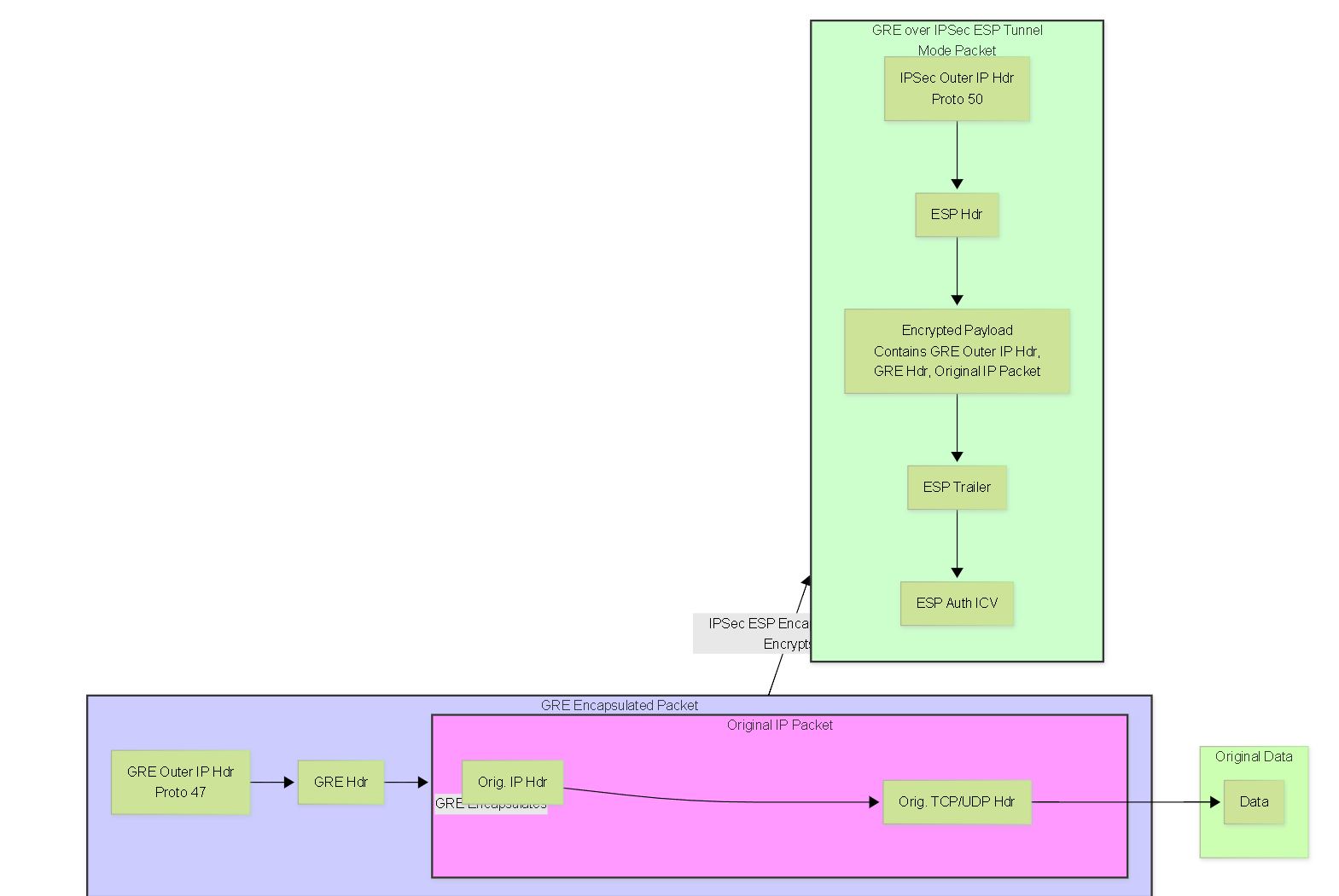
GRE over IPSec Encapsulation Flow.
The Outer IP Header (IPSec Endpoints) is what routers on the public internet see and use for routing the encrypted packet between the IPSec gateways (e.g., Palo Alto Networks firewalls).
The New IP Header (GRE Endpoints) within the encrypted payload is used by the GRE protocol itself to identify the logical source and destination of the GRE tunnel. These are typically the same as the IPSec endpoint IPs if the "Add GRE Encapsulation" option is used on the IPSec tunnel in PAN-OS, or they can be different if separate tunnel interfaces are used for GRE and IPSec.
Configuration & Best Practices
Palo Alto Networks GRE Configuration
Configuring a basic GRE tunnel on a Palo Alto Networks firewall involves several steps, primarily through the WebUI. PAN-OS version 9.0 and later support GRE tunnels.
1. Configure Tunnel Interface
A logical tunnel interface is required for the GRE tunnel.
-
Navigate to
Network > Interfaces > Tunnel. -
Click
Addto create a new tunnel interface (e.g.,tunnel.1). -
Config Tab:
-
Assign it to a
Virtual Router
(e.g.,
default). -
Assign it to a
Security Zone
(e.g., create a new zone like
ZONE-GRE-TUNNELSor use an existing one likeTrustorVPN). This is crucial for policy enforcement.
-
Assign it to a
Virtual Router
(e.g.,
-
IPv4 Tab:
-
Assign an
IP address and subnet mask
to this tunnel interface (e.g.,
10.0.0.1/30). This IP is used for routing traffic *through* the tunnel and for dynamic routing protocol adjacencies if used. The IP addresses on both sides of the GRE tunnel for their respective tunnel interfaces should be in the same subnet.
-
Assign an
IP address and subnet mask
to this tunnel interface (e.g.,
- Adjust MTU if necessary (default is 1500, may need reduction, see MTU/MSS section).
2. Configure GRE Tunnel Object
Define the GRE tunnel parameters.
-
Navigate to
Network > GRE Tunnels. -
Click
Add. -
Name:
Provide a descriptive name (e.g.,
GRE-to-SiteB). -
Tunnel Interface:
Select the tunnel interface created in step 1 (e.g.,
tunnel.1). -
Local Interface:
Select the physical or logical interface on the firewall that will be the source of the GRE packets (e.g., your external-facing interface like
ethernet1/1). -
Local IP Address:
Select the IP address of the
Local Interfacethat will be used as the source IP for the outer GRE packet header. - Peer IP Address: Enter the public IP address of the remote GRE tunnel endpoint (the other firewall/router).
- Copy ToS Header: (Optional) Enable if you want to copy the ToS (Type of Service) bits from the inner packet's IP header to the outer GRE IP header.
- Keep-alive: (Optional) Enable to send keep-alive packets to monitor tunnel status. Default is 10-second interval, 3 retries. If used, ensure settings are compatible with the peer. Sometimes disabling keepalives can resolve flapping issues if not properly diagnosed.
- The Local IP Address on one side must correspond to the Peer IP Address on the other side.
-
The IP addresses assigned to the
tunnel interfaces
(e.g.,
tunnel.1) on both ends must be in the same subnet. For example, if PA-A tunnel.1 is 10.0.0.1/30, PA-B tunnel.1 could be 10.0.0.2/30. - Keep-alive parameters, if enabled, should generally match or be compatible.
3. Configure Routing
You need to route traffic destined for the remote network(s) through the GRE tunnel.
-
Navigate to
Network > Virtual Routersand select your virtual router. - Go to Static Routes .
-
Click
Add:- Name: Descriptive name.
-
Destination:
The remote network (e.g.,
192.168.2.0/24). -
Interface:
Select the GRE tunnel interface (e.g.,
tunnel.1). -
Next Hop:
Typically, for a tunnel interface, you can select
Noneif the tunnel interface has an IP and is point-to-point. Alternatively, specify the IP address of the remote tunnel interface (e.g.,10.0.0.2if PA-A is10.0.0.1).
- Alternatively, configure a dynamic routing protocol (OSPF, BGP) to run over the GRE tunnel interface (see Dynamic Routing section).
4. Configure Security Policies
Security policies are required to allow traffic to flow between zones and through the tunnel.
-
Allow Traffic Through the Tunnel:
-
Create policies from your source zone (e.g.,
Trust) to the destination zone of the tunnel interface (e.g.,ZONE-GRE-TUNNELSorVPN) for the traffic you want to permit. - And from the tunnel's zone back to your internal zones for return traffic.
- Specify source/destination addresses, applications, and services as needed.
-
Create policies from your source zone (e.g.,
-
Allow Incoming GRE Traffic (IP Protocol 47):
A crucial step often missed! If the GRE tunnel interface is in a different zone than the physical interface receiving the GRE packets (e.g., tunnel in
ZONE-GRE-TUNNELS, physical interface inUntrust), you MUST create a security policy to allow IP protocol 47 (GRE) from the external zone to the zone of the GRE tunnel interface.-
Source Zone:
Zone of the physical interface receiving GRE packets (e.g.,
Untrust). - Source Address: Public IP of the remote GRE peer.
-
Destination Zone:
Zone of the GRE tunnel interface (e.g.,
ZONE-GRE-TUNNELS). - Destination Address: Public IP of the local firewall (the GRE endpoint).
-
Application:
gre(or create a custom service for IP protocol 47). - Action: Allow.
-
Source Zone:
Zone of the physical interface receiving GRE packets (e.g.,
Palo Alto Networks GRE over IPSec Configuration
Configuring GRE over IPSec involves setting up both the GRE components (as described previously) and the IPSec components. Palo Alto Networks provides a streamlined way to do this, especially when the GRE tunnel endpoints are the same as the IPSec tunnel endpoints.
Scenario 1: GRE and IPSec Share Same Endpoints (Recommended Approach)
In this common scenario, the source and destination IP addresses for both the GRE tunnel and the IPSec tunnel are the same (i.e., the public IPs of the firewalls). PAN-OS allows you to associate GRE encapsulation directly with an IPSec tunnel.
-
Configure Tunnel Interface:
-
Create one tunnel interface (e.g.,
tunnel.1). - Assign it to a Virtual Router and Security Zone.
-
Assign an IP address (e.g.,
10.0.0.1/30). This IP is for the logical GRE link.
-
Create one tunnel interface (e.g.,
-
Configure IKE Crypto Profile (Phase 1):
-
Navigate to
Network > Network Profiles > IKE Crypto. ClickAdd. - Define DH Group, Encryption, Authentication, and Key Lifetime. These must match the peer.
-
Navigate to
-
Configure IKE Gateway (Phase 1):
-
Navigate to
Network > Network Profiles > IKE Gateways. ClickAdd. - Name: Descriptive name.
- Version: IKEv1 or IKEv2 (IKEv2 recommended).
- Interface: Your external-facing physical interface.
- Local IP Address: Your firewall's public IP.
- Peer IP Address: The remote firewall's public IP.
-
Authentication:
Pre-Shared Key or Certificate.
- If PSK, enter and confirm the key.
- Local Identification & Peer Identification: (Optional but good practice) Specify FQDN, IP address, etc. These must match what the peer expects.
- Advanced Options Tab: Select the IKE Crypto Profile created above.
-
Navigate to
-
Configure IPSec Crypto Profile (Phase 2):
-
Navigate to
Network > Network Profiles > IPSec Crypto. ClickAdd. - Name: Descriptive name.
- IPSec Protocol: ESP (recommended).
- Define Encryption, Authentication, DH Group (for PFS if used), and Lifetime. These must match the peer.
-
Navigate to
-
Configure IPSec Tunnel (Phase 2 & GRE Integration):
-
Navigate to
Network > IPSec Tunnels. ClickAdd. - Name: Descriptive name.
-
Tunnel Interface:
Select the tunnel interface created in step 1 (e.g.,
tunnel.1). This interface will now serve both GRE and IPSec. - Type: Auto Key.
- IKE Gateway: Select the IKE Gateway created above.
- IPSec Crypto Profile: Select the IPSec Crypto Profile created above.
- Show Advanced Options > GRE Encapsulation: Check the "Add GRE Encapsulation" box. This is the key step that tells PAN-OS to expect GRE traffic (protocol 47) to be encapsulated by this IPSec tunnel.
-
Proxy IDs Tab (Traffic Selectors):
-
Click
Add. - Proxy ID Name: Descriptive.
- Local: The local firewall's public IP address (the GRE tunnel source).
- Remote: The remote firewall's public IP address (the GRE tunnel destination).
-
Protocol:
Select
GRE (value 47). -
Alternatively, some configurations might use
0.0.0.0/0for Local/Remote andAnyfor Protocol if the tunnel is purely route-based and dynamic routing handles specificity. However, specifying protocol 47 and the tunnel endpoints is more precise and secure for GRE over IPSec. - Ensure the Proxy IDs are a mirror image of the configuration on the peer device.
-
Click
- Tunnel Monitor: (Optional) Configure to monitor the tunnel's health, typically by pinging the remote tunnel interface IP.
-
Navigate to
-
Configure Routing:
Use static routes or dynamic routing protocols pointing to the tunnel interface (
tunnel.1) as before. The routing is for the inner, original traffic. -
Configure Security Policies:
- Allow application traffic between your internal zones and the tunnel's zone.
- You typically do NOT need a separate policy to allow "gre" application or IP protocol 47 from Untrust for this scenario because the IPSec tunnel itself handles the decapsulation of the outer IP (protocol 50 for ESP) and then the "Add GRE Encapsulation" feature handles the GRE decapsulation. The traffic presented to the policy engine will be the inner IP packet.
Network > GRE Tunnels
) AND an IPSec Tunnel both assigned to the *same* tunnel interface when using the "Add GRE Encapsulation" checkbox, the commit will fail. The checkbox method handles the GRE aspect implicitly within the IPSec tunnel configuration.
Scenario 2: GRE and IPSec Use Different Endpoints/Interfaces
This is a less common and more complex setup where, for example, an IPSec tunnel terminates on one pair of interfaces, and then a GRE tunnel is built "over" that established secure path using different logical interfaces or IP addresses.
In this case:
-
You would configure a standard IPSec tunnel between two firewalls using a dedicated tunnel interface (e.g.,
tunnel.10for IPSec). The Proxy IDs for this IPSec tunnel would cover the traffic that the GRE tunnel itself will generate (i.e., the IP addresses you'll use for the GRE tunnel endpoints over the secure path). -
Then, you would configure a separate GRE tunnel (
Network > GRE Tunnels) using another tunnel interface (e.g.,tunnel.20for GRE). The "Local Interface" for this GRE tunnel would be the IPSec tunnel interface (tunnel.10), and the Local/Peer IP addresses for the GRE tunnel would be routable via the IPSec tunnel. - This essentially creates a GRE tunnel that believes its underlying transport network is the secure path established by the IPSec tunnel.
This method requires careful routing to ensure GRE packets are directed into the IPSec tunnel and then correctly routed after decapsulation. It involves two distinct tunnel interfaces on the Palo Alto Networks firewall.
Dynamic Routing over GRE / GRE over IPSec
One of the primary advantages of using GRE tunnels (including GRE over IPSec) is their ability to transport multicast and broadcast traffic, which allows dynamic routing protocols like OSPF, EIGRP, BGP, and RIP to operate across the tunnel. This enables networks to exchange routing information dynamically, providing resilience and simplifying route management in complex topologies.
Configuration Steps (General):
-
Establish the Tunnel:
- Configure the GRE or GRE over IPSec tunnel as previously described.
-
Ensure the tunnel interface (e.g.,
tunnel.1) has an IP address. Both ends of the tunnel must have IP addresses in the same subnet (e.g., PA-A:10.0.0.1/30, PA-B:10.0.0.2/30). - Verify basic IP connectivity across the tunnel interface IPs (e.g., ping the remote tunnel interface IP from the local firewall CLI sourced from the local tunnel interface IP).
-
Configure the Routing Protocol on Palo Alto Networks Firewall:
-
Navigate to
Network > Virtual Routersand select your virtual router. -
Go to the specific routing protocol section (e.g.,
OSPF,BGP). - Enable the protocol.
- Set a Router ID .
-
For OSPF:
-
Define an
Area
(e.g.,
0.0.0.0for backbone). -
Under the Area configuration, add the GRE tunnel interface (e.g.,
tunnel.1).-
Set the Link Type (e.g.,
p2pfor point-to-point). - Configure timers, authentication, etc., as needed, ensuring they match the peer.
-
Set the Link Type (e.g.,
- Add other local interfaces/networks to OSPF that you want to advertise to the remote side.
- Consider OSPF network types. Some types use multicast for neighbor discovery which GRE supports. If running OSPF directly over an IPSec tunnel (without GRE), multicast might not work, requiring specific configurations or unicast neighbor statements.
-
Define an
Area
(e.g.,
-
For BGP:
- Configure BGP settings (Local AS, Router ID).
- Define a Peer Group.
-
Add a Peer to the group:
- Peer Address: The IP address of the remote GRE tunnel interface.
- Remote AS: The AS number of the remote BGP peer.
- Configure address families (e.g., IPv4) and network advertisements/redistribution.
- Ensure any necessary redistribution profiles are configured if you're redistributing routes from other protocols or static routes into the dynamic routing protocol.
-
Navigate to
-
Configure the Routing Protocol on the Peer Device:
- Configure the corresponding routing protocol (OSPF, BGP, etc.) on the remote router/firewall.
- Ensure parameters like AS numbers (for BGP), OSPF area IDs, authentication keys, and timers match or are compatible with the Palo Alto Networks firewall configuration.
-
Verify Adjacency/Peering:
-
Use CLI commands on both devices to check if the routing protocol adjacency or BGP peering has been established.
-
Palo Alto Networks CLI:
show routing protocol ospf neighbor,show routing protocol bgp peer.
-
Palo Alto Networks CLI:
-
Use CLI commands on both devices to check if the routing protocol adjacency or BGP peering has been established.
-
Verify Route Propagation:
-
Check the routing tables on both devices to ensure routes are being learned dynamically over the tunnel.
-
Palo Alto Networks CLI:
show routing route.
-
Palo Alto Networks CLI:
-
Check the routing tables on both devices to ensure routes are being learned dynamically over the tunnel.
-
Security Policies:
- Ensure security policies allow the routing protocol traffic between the firewalls over the tunnel interface. For OSPF, this is IP protocol 89. For BGP, this is TCP port 179. The "application" for these protocols should be allowed between the zone containing the tunnel interface and itself (if peers are in the same zone via tunnel) or between relevant zones.
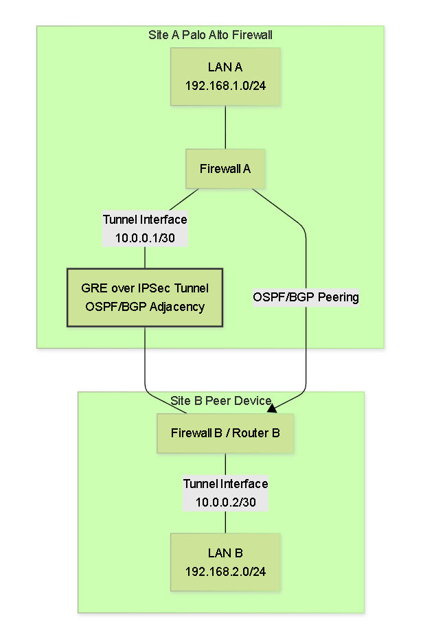
Dynamic Routing over a GRE/IPSec Tunnel.
MTU Considerations for Routing Protocols: Routing protocol packets (like OSPF Hellos or BGP Updates) must also fit within the tunnel's effective MTU. Large numbers of LSAs in OSPF or many prefixes in BGP can lead to larger packets. While fragmentation can occur, ensuring sufficient MTU or adjusting protocol parameters (like OSPF MTU ignore options, though use with caution) might be necessary in some cases. Mismatched MTU can sometimes prevent adjacencies from forming.
MTU and TCP MSS Adjustments
When implementing GRE or GRE over IPSec tunnels, it's critical to correctly adjust the Maximum Transmission Unit (MTU) and TCP Maximum Segment Size (MSS) values. Failure to do so can lead to packet fragmentation or drops, severely degrading performance or causing connectivity failures.
Understanding Overhead
- GRE Overhead: Adds a GRE header (typically 4 bytes for basic GRE) and a new outer IP header (20 bytes for IPv4). Total = 24 bytes .
-
IPSec (ESP) Overhead:
This is more variable depending on the chosen algorithms and mode. For ESP in Tunnel Mode, it includes:
- New Outer IP Header: 20 bytes (IPv4)
- ESP Header: ~8 bytes
- Initialization Vector (IV): 8 bytes (e.g., for DES, 3DES) or 16 bytes (e.g., for AES).
- ESP Trailer (Padding, Pad Length, Next Header): Variable, ensures payload aligns to block cipher boundary.
- Integrity Check Value (ICV) / ESP Auth: ~12 bytes (e.g., SHA1/SHA256).
- Common ESP Overhead Range: Approximately 50-75 bytes on top of the original packet (this already includes the new IP header if considering ESP Tunnel mode's impact on the GRE packet). For just the ESP-specific additions beyond the new IP header, it's around 30-55 bytes.
Example Total Overhead = Original IP -> GRE (24 bytes) -> IPSec ESP (adds ~52 bytes for its own headers, IV, ICV, new outer IP) = ~76 bytes (if GRE's outer IP is replaced by IPSec's outer IP).
More simply: Path MTU - GRE (24 bytes) - IPSec ESP additions (e.g., 52 bytes excluding the GRE outer IP but including a new IPSec outer IP) gives the effective MTU for the original packet.
A common calculation:
Path MTU (e.g., 1500)
- GRE specific addition (4 bytes)
- IPSec ESP additions (e.g., ~52 bytes including a new outer IP header, ESP headers, IV, ICV but not counting the GRE packet's own outer header which is now inside)
This can be complex. A simpler way is to subtract known fixed overheads sequentially.
MTU Calculation Example
Assume a standard internet path MTU of 1500 bytes.- Path MTU: 1500 bytes
-
GRE Encapsulation:
- GRE Header: 4 bytes
- New Outer IP Header for GRE: 20 bytes
- MTU for packet entering GRE tunnel = 1500 - 24 = 1476 bytes .
-
GRE over IPSec (ESP Tunnel Mode) Encapsulation:
The GRE packet (now 1476 bytes max) is further encapsulated by IPSec.
- Assume IPSec ESP overhead (including its own new outer IP header, ESP header, IV, trailer, ICV) is roughly ~50-70 bytes . Let's use ~56 bytes as an example (this value can vary significantly based on encryption/authentication algorithms and padding). This 56 bytes includes the new IPsec outer header (20 bytes). The calculation for the *tunnel interface MTU* on the Palo Alto Networks firewall, which represents the size of the IP packet *before* IPSec encryption but *after* GRE encapsulation (if GRE is handled by the same logical interface that IPSec uses) should be: Physical MTU (1500) - IPSec Overhead (e.g. 56 bytes) = 1444 bytes. If GRE is applied first, the original packet becomes [GRE headers + Original Packet]. This whole GRE unit is then passed to IPSec. So, for the original packet: Path MTU = 1500 bytes Subtract IPSec Overhead (e.g., 56 bytes for ESP with new IP header): 1500 - 56 = 1444 bytes (this is the MTU the IPSec tunnel interface can handle for its payload) Subtract GRE Overhead (24 bytes, consisting of its IP header and GRE header which are *inside* the IPSec payload): 1444 - 24 = 1420 bytes . This is the effective MTU for the original data packet. The Palo Alto Networks tunnel interface MTU should be set to accommodate the largest packet *before* the final layer of encryption. If the same tunnel interface handles GRE-over-IPSec via the "Add GRE Encapsulation" checkbox, then its MTU should be set considering the IPSec overhead. Effective Tunnel MTU = Physical Interface MTU - IPSec Overhead E.g., 1500 - (approx. 56 to 72 bytes for ESP) = ~1428 to ~1444 bytes. Then, applications sending data that will be GRE encapsulated *before* hitting this IPSec tunnel must consider the additional 24-byte GRE overhead. A common rule of thumb for combined GRE over IPSec is to reduce the MTU on the tunnel interface to around 1400 bytes to be safe, but calculation is better. If the tunnel interface MTU on the firewall is set to (Path MTU - IPSec overhead), e.g., 1440. And then GRE adds 24 bytes. Original packet MTU = 1440 - 24 = 1416.
Network > Interfaces > Tunnel > Advanced
). For GRE over IPSec where "Add GRE Encapsulation" is used, this tunnel interface MTU should be the physical MTU minus the IPSec overhead. The firewall then accounts for the GRE encapsulation internally.
TCP MSS (Maximum Segment Size) Adjustment
TCP MSS is the maximum amount of actual data that can be in a single TCP segment. It is calculated as MTU - IP Header (20 bytes) - TCP Header (20 bytes).
If the MTU is reduced due to tunnel overhead, the MSS must also be reduced to prevent TCP packets from becoming too large and requiring fragmentation *after* TCP segmentation but *before* or *during* encapsulation.
- Calculation: New MSS = Tunnel Interface MTU - 40 bytes (20 for IP, 20 for TCP).
-
Example: If effective MTU for original packet is 1420 bytes (after GRE and IPSec overhead):
New MSS = 1420 - 40 = 1380 bytes . -
If the Palo Alto Networks tunnel interface MTU is set to 1440 (to account for IPSec overhead), and GRE is handled by that interface:
MSS for traffic *entering* the GRE encapsulation = 1440 (tunnel MTU) - 24 (GRE) - 40 (IP/TCP) = 1376 bytes .
Palo Alto Networks firewalls can automatically adjust the MSS value in TCP SYN packets that pass through an interface or zone.
-
This is configured under
Network > Interfaces > Tunnel > Advanced > Adjust TCP MSSor on the Zone containing the tunnel interface underNetwork > Zones > [Your Zone] > Adjust TCP MSS. - When enabling "Adjust TCP MSS", you can select "IPSec" which automatically calculates a suitable MSS based on a standard IPSec overhead, or manually specify an MSS value. For GRE over IPSec, if "IPSec" option doesn't account for GRE, manual might be needed or ensure tunnel MTU is already reduced for GRE. A common MSS clamp value for GRE tunnels is 1436 bytes (1476 GRE MTU - 40). For GRE over IPSec, this would be lower.
Troubleshooting GRE & GRE over IPSec Tunnels
Troubleshooting tunnel issues involves a layered approach, checking connectivity, configuration, and logs.
Common Issues:
-
GRE Tunnel Down/Flapping:
- Mismatched GRE endpoint IPs.
- Routing issues to peer GRE endpoint IPs.
- Firewall policies blocking IP Protocol 47 (GRE).
- Keep-alive issues (mismatched settings or network drops). Sometimes disabling keepalives temporarily can help isolate issues.
- Underlying network connectivity problems.
-
IPSec Phase 1 Failures:
- Mismatched Pre-Shared Keys.
- Mismatched IKE Crypto Profile parameters (DH Group, Encryption, Hash, Lifetime).
- Incorrect IKE Gateway peer IP or local/peer identification.
- Firewall policies blocking UDP 500/4500 (IKE/NAT-T).
- No route to the peer.
-
IPSec Phase 2 Failures:
- Mismatched IPSec Crypto Profile parameters (Protocol, Encryption, Auth, PFS DH Group, Lifetime).
- Mismatched or incorrectly configured Proxy IDs (Traffic Selectors). This is a very common issue, especially for GRE over IPSec where Proxy IDs must cover GRE protocol 47 between the tunnel endpoints.
-
Traffic Not Passing Through an "Up" Tunnel:
- Routing issues (no route for destination via tunnel, or asymmetric routing).
- Security policies blocking the actual data traffic.
- NAT issues (e.g., NAT traversal for IPSec, or unwanted NAT on tunneled traffic). For GRE, ensure NAT exclusion for traffic entering the GRE tunnel if source IP needs to be preserved.
- MTU/MSS issues causing fragmentation and drops.
Palo Alto Networks Troubleshooting Tools & Commands (CLI):
-
Check Tunnel Interface Status:
show interface tunnel.<id>(e.g.,show interface tunnel.1)
Look for: Interface state (Up/Down), IP address, MTU. For GRE, it might also show GRE tunnel specific state. -
Check GRE Tunnel Status:
show global-protect-gateway PANGpGreTunnel status tunnel-name <gre_tunnel_object_name>(Older command, might be specific)
A more general approach isshow plugins PANGpGreTunnel status tunnel-name <gre_tunnel_object_name>
Or simply check system logs for GRE events:show log system subtype equal gre. -
Check IPSec Tunnel Status (IKE SAs - Phase 1):
show vpn ike-sa gateway <ike_gateway_name>
Look for: State (should be ESTABLISHED), local/remote IPs, algorithms. -
Check IPSec Tunnel Status (IPSec SAs - Phase 2):
show vpn ipsec-sa tunnel <ipsec_tunnel_name>
Look for: State (should be ESTABLISHED), SPIs, encryption/auth algorithms, lifesize/lifetime, encapsulation/decapsulation counters (to see if traffic is flowing). -
Test Connectivity:
ping source <local_tunnel_interface_ip> host <remote_tunnel_interface_ip>
ping source <local_lan_ip> host <remote_lan_ip> -
Check Routing Table:
show routing route
Ensure routes exist for remote networks via the tunnel interface. -
Check Logs:
-
System Logs:
For tunnel up/down events, IKE negotiations.
show log system subtype equal vpn
show log system subtype equal gre
less mp-log ikemgr.log(for detailed IKE negotiation, requires debugs to be useful sometimes)
less mp-log vpnmgr.log(for IPSec management) - Traffic Logs (Monitor Tab in GUI): To see if traffic is being allowed or denied by security policies, or if it's even reaching the firewall. Filter by source/destination IPs, zones, and tunnel interface.
-
System Logs:
For tunnel up/down events, IKE negotiations.
-
Packet Captures (CLI or GUI: Monitor > Packet Capture):
- Capture on physical external interface for IKE (UDP 500/4500) or outer GRE/IPSec packets (IP proto 47/50).
- Capture on the tunnel interface to see traffic before encapsulation / after decapsulation.
- Filter effectively to narrow down relevant packets.
-
Debugs (Use with caution, can impact performance):
debug ike global on dump(very verbose IKE logging)
debug routing pbf on(for Policy Based Forwarding)
Always turn off debugs after use:debug ike global off
- IKE Phase 1: "Phase 1 proposal mismatch", "Pre-shared key mismatch", "No proposal chosen".
- IKE Phase 2: "Phase 2 proposal mismatch", "Proxy ID mismatch", "No proposal chosen", "TS_UNACCEPTABLE".
- GRE: "GRE tunnel status changed to Up/Down".
- Traffic logs showing denies for expected traffic or for protocol 47/50/500/4500.
PCNSE Insights
Key Exam Topics for GRE & GRE over IPSec
For the Palo Alto Networks Certified Network Security Engineer (PCNSE) exam, a solid understanding of GRE and GRE over IPSec is essential. Focus on the following areas:
Conceptual Understanding:
- When to Use GRE: Know the scenarios where GRE is appropriate (multicast, routing protocols over tunnels, non-IP traffic) and its limitations (no inherent security).
- When to Use GRE over IPSec: Understand the benefits of combining GRE's flexibility with IPSec's security, especially for secure multicast and dynamic routing.
- GRE Packet Structure: Basic headers and total overhead (24 bytes for GRE + New IP).
-
IPSec Fundamentals:
- IKE Phase 1: Purpose, key parameters (DH Group, Auth, Enc, Hash, Lifetime), PSK vs. Certificates.
- IKE Phase 2: Purpose, key parameters (ESP/AH, Enc, Auth, Lifetime, PFS), Tunnel vs. Transport mode.
- AH vs. ESP: Services provided by each, and why ESP is more common.
Configuration on Palo Alto Networks Firewalls:
- Tunnel Interface: Creation, assignment to Virtual Router and Security Zone, IP addressing.
- GRE Tunnel Object: Local/Peer IPs, local interface, association with tunnel interface.
-
IPSec Components:
- IKE Crypto Profile (Phase 1 parameters).
- IKE Gateway (Peer info, authentication, IKE Crypto Profile link).
- IPSec Crypto Profile (Phase 2 parameters).
- IPSec Tunnel object (linking IKE Gateway, IPSec Crypto, tunnel interface).
-
GRE over IPSec Specifics:
- The "Add GRE Encapsulation" checkbox in the IPSec Tunnel configuration.
- Correct Proxy ID configuration for GRE over IPSec (must allow GRE protocol 47 between the public tunnel endpoints).
- Routing: Static routes vs. dynamic routing (OSPF, BGP) over the tunnel interface.
-
Security Policies:
- Allowing application traffic through the tunnel (between relevant zones).
- The special policy required to allow incoming GRE (IP protocol 47) if the GRE tunnel interface and physical ingress interface are in different zones for plain GRE.
-
MTU and MSS:
- Calculating overhead for GRE and IPSec.
- Setting MTU on the tunnel interface.
- Configuring TCP MSS adjustment (interface or zone level, "IPSec" option or manual value).
Troubleshooting:
- Common reasons for tunnel failures (mismatched parameters, routing, policies, MTU/MSS).
-
Key CLI commands to check tunnel status (
show interface tunnel,show vpn ike-sa,show vpn ipsec-sa). - Interpreting System and Traffic logs for VPN/GRE events.
- Basic packet capture interpretation for tunnel traffic.
Common Pitfalls & Caveats (PCNSE Focus)
Be aware of these common mistakes and important details for the exam and real-world deployments:
- Incorrect Proxy IDs for GRE over IPSec: This is a major one. If using the "Add GRE Encapsulation" feature, the Proxy IDs in the IPSec tunnel configuration MUST specify protocol 47 (GRE) and the source/destination IPs should be the public GRE/IPSec tunnel endpoints. Using internal LAN subnets as Proxy IDs here will prevent GRE traffic from being properly encapsulated by IPSec.
- MTU/MSS Misconfiguration: Leading to fragmentation, packet drops, or slow performance. Ensure correct calculation and application of MTU on the tunnel interface and TCP MSS clamping. Remember GRE adds 24 bytes, and IPSec adds more.
- Missing Security Policy for GRE Protocol 47: For plain GRE tunnels (not GRE over IPSec using the "Add GRE Encapsulation" method), if the tunnel interface is in a different zone than the physical interface receiving GRE packets, a policy allowing IP protocol 47 from the source (external peer) to the destination (local firewall's public IP, destined for the tunnel zone) is required.
- Mismatched IPSec Parameters: All IKE Phase 1 and Phase 2 parameters (encryption, hash, DH group, PSK, lifetimes, etc.) must match or be compatible between peers. Any mismatch will cause tunnel negotiation failures.
-
Routing Issues:
- No route to the remote network via the tunnel.
- Asymmetric routing where return traffic doesn't come back through the firewall or tunnel.
- Incorrect next-hop for static routes over tunnels.
- Dynamic routing protocols not forming adjacencies due to mismatched parameters, MTU issues, or policies blocking protocol traffic.
- Zone Placement of Tunnel Interface: The tunnel interface must be in a security zone. Policies are written based on traffic flowing between zones, including the zone containing the tunnel interface.
- NAT Traversal (NAT-T): If an IPSec peer is behind a NAT device, NAT-T (encapsulating IPSec ESP packets in UDP 4500) must be enabled on both peers for IKE and IPSec to function correctly. Palo Alto Networks firewalls typically auto-detect and use NAT-T if needed.
- Order of Operations: For GRE over IPSec, GRE encapsulation happens first, then IPSec. The firewall processes packets in a specific order (ingress, flow lookup, NAT, VPN decapsulation, policy, etc.).
- Stateless GRE vs. Stateful Security Policy: GRE itself is stateless, but traffic passing through a Palo Alto Networks firewall, including tunneled traffic, is subject to stateful security policy inspection.
-
Single Tunnel Interface for "Add GRE Encapsulation":
When using the "Add GRE Encapsulation" checkbox in the IPSec tunnel configuration, only ONE tunnel interface is used for both GRE and IPSec. Attempting to assign this same tunnel interface to a separate GRE Tunnel object (
Network > GRE Tunnels) will result in a commit error. - Keep-alives: While GRE keep-alives can monitor tunnel health, they can also sometimes cause flapping if network conditions are unstable or if mismatched with the peer. For GRE over IPSec, IPSec's Dead Peer Detection (DPD) or tunnel monitoring features are often preferred.
GRE & GRE over IPSec Quiz
Test your knowledge on Palo Alto Networks GRE and GRE over IPSec.