Introduction to IPSec
IPSec (Internet Protocol Security) is a mandatory part of IPv6 and optional (but widely used) for IPv4. It's a framework of open standards developed by the Internet Engineering Task Force (IETF) to ensure private, secure communications over Internet Protocol (IP) networks. IPSec provides security services at the IP layer (Layer 3), offering protection for IP and upper-layer protocols (like TCP, UDP, ICMP) transparently to applications.
Core Security Goals
IPSec aims to provide the following security services, often referred to by the acronym **CIA+**:- Confidentiality (Encryption): Preventing unauthorized disclosure of data content. Ensures that even if traffic is intercepted, it cannot be read without the correct decryption key. Primarily provided by ESP.
- Integrity (Hashing): Ensuring data has not been altered (accidentally or maliciously) during transit. Detects any modification to the protected data. Provided by both AH and ESP (with authentication).
-
Authentication (Data Origin Authentication & Peer Authentication):**
- **Data Origin Authentication:** Verifies that the data received actually came from the claimed sender. Provided by AH and ESP (with authentication).
- **Peer Authentication:** Verifies the identity of the remote IPSec device (gateway or host) *before* establishing the secure tunnel. Handled by IKE (using PSK, Certificates, or EAP).
- Anti-Replay Protection: Preventing attackers from capturing legitimate packets and retransmitting them later to disrupt communication or gain unauthorized access. Both AH and ESP use sequence numbers to achieve this.
Key Components & Concepts
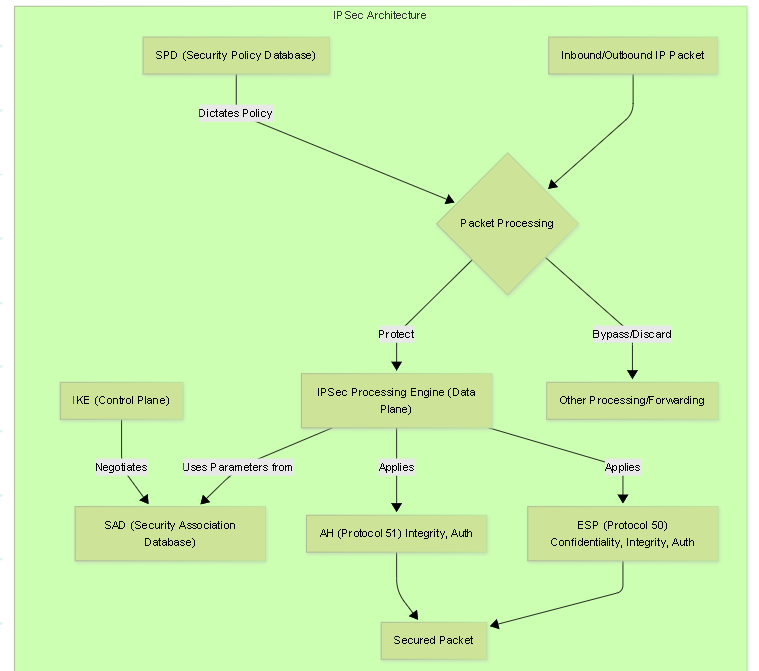
IPSec isn't a single protocol but a suite. Understanding these components is crucial:- Internet Key Exchange (IKE): The control plane protocol (UDP ports 500/4500). Negotiates security parameters, authenticates peers, generates cryptographic keys, and establishes Security Associations (SAs) for both IKE itself and for IPSec (AH/ESP). Versions include IKEv1 and the modern IKEv2.
- Authentication Header (AH): IP Protocol 51 . Provides integrity, data origin authentication, and anti-replay for the *entire* IP packet (including immutable parts of the header). Does NOT provide confidentiality (encryption). Incompatible with NAT.
- Encapsulating Security Payload (ESP): IP Protocol 50 . Provides confidentiality (encryption) and optionally integrity, data origin authentication, and anti-replay. Protects the IP payload (Transport mode) or the entire original IP packet (Tunnel mode). Compatible with NAT (when using NAT-T). This is the most commonly used IPSec protocol.
- Security Association (SA): A unidirectional logical connection established by IKE, defining the specific security parameters (protocol, algorithms, keys, lifetimes, etc.) used to protect traffic between two peers. For bidirectional communication, two SAs are required (one inbound, one outbound). SAs are stored in the Security Association Database (SAD).
- Security Policy Database (SPD): Defines *which* traffic should be protected by IPSec, bypassed, or discarded based on selectors (like source/destination IP, protocol, port). Outbound packets are checked against the SPD to determine if IPSec processing is needed. Inbound IPSec packets, after decryption/authentication, might also be checked against SPD policies.
- Algorithms: Specific cryptographic functions used for encryption (e.g., AES, 3DES), hashing/integrity (e.g., SHA-256, SHA-1), authentication (HMAC variants), and key exchange (e.g., Diffie-Hellman groups).
Common Use Cases
- Site-to-Site VPNs: Securely connecting two or more geographically separate networks (e.g., connecting branch offices to headquarters) over the public internet using VPN gateways (firewalls/routers). Typically uses ESP in Tunnel Mode.
- Remote Access VPNs: Allowing individual users (e.g., employees working from home) to securely connect to a corporate network over the internet. Often involves a software client on the user's device connecting to a VPN gateway. IKEv2 with EAP is common here.
- Securing Other Protocols: IPSec can be used to add security to protocols that lack it, such as L2TP (Layer 2 Tunneling Protocol). L2TP/IPSec combines L2TP's tunneling with IPSec's security.
The following sections will delve into each of these components in greater detail.
IKE Overview: The Control Plane
The Internet Key Exchange (IKE) protocol is the heart of the IPSec control plane. It operates in user space and communicates using UDP, typically starting on port 500 . Its core mission is to dynamically and securely establish the parameters needed for the IPSec data plane (AH and ESP).
IKE itself is built upon the ISAKMP (Internet Security Association and Key Management Protocol) framework (RFC 2408), which defines packet formats, state transitions, and notification mechanisms. While ISAKMP provides the structure, IKE defines the specific key exchange protocols (like Oakley) and modes used within that structure.
Key Functions of IKE
- Negotiation of Security Parameters: Peers propose and agree upon the specific cryptographic algorithms (encryption, hashing, DH group) and other attributes (lifetimes, mode) to be used for both the IKE SA itself and the subsequent IPSec (Child) SAs.
- Diffie-Hellman (DH) Key Exchange: Securely establishes shared secret keys between peers over an untrusted network without transmitting the keys directly. These shared secrets form the basis for deriving the actual encryption and authentication keys.
-
Peer Authentication:
Verifies the identity of the communicating peers before sensitive keying material or data SAs are established. Common methods include:
- Pre-Shared Keys (PSK): Simple but less scalable/secure.
- Digital Certificates (PKI): Scalable and strong authentication.
- EAP (Extensible Authentication Protocol - IKEv2 only): Flexible methods for user authentication, often used in remote access.
-
Establishment and Management of Security Associations (SAs):
- Creates the initial secure channel, known as the IKE SA (protected by parameters agreed upon during the initial negotiation).
- Uses the IKE SA to securely negotiate and establish one or more IPSec SAs (referred to as Child SAs in IKEv2) that define how AH or ESP will protect the actual user data.
- Manages SA lifetimes and handles the rekeying process to generate fresh keys and new SAs before the current ones expire, maintaining ongoing security.
- NAT Traversal (NAT-T) Detection and Handling: Detects if Network Address Translation devices exist between peers and, if so, encapsulates IPSec traffic within UDP (typically switching to port 4500 ) to bypass NAT issues.
- Dead Peer Detection (DPD): Provides a mechanism to detect if an IPSec peer has become unresponsive, allowing for timely cleanup of SAs and potentially triggering failover mechanisms.
IKE Versions
- IKEv1 (RFC 2409): The original version. Characterized by distinct Phase 1 (Main/Aggressive Mode) and Phase 2 (Quick Mode). Less efficient and lacks some modern features natively.
- IKEv2 (RFC 7296): The current standard. Streamlined negotiation (4 messages initial exchange), built-in reliability, NAT-T, DPD, MOBIKE, EAP support. Significantly improved and preferred for new deployments.
Understanding IKE is fundamental because if IKE fails to establish the SAs, no data will be protected by IPSec.
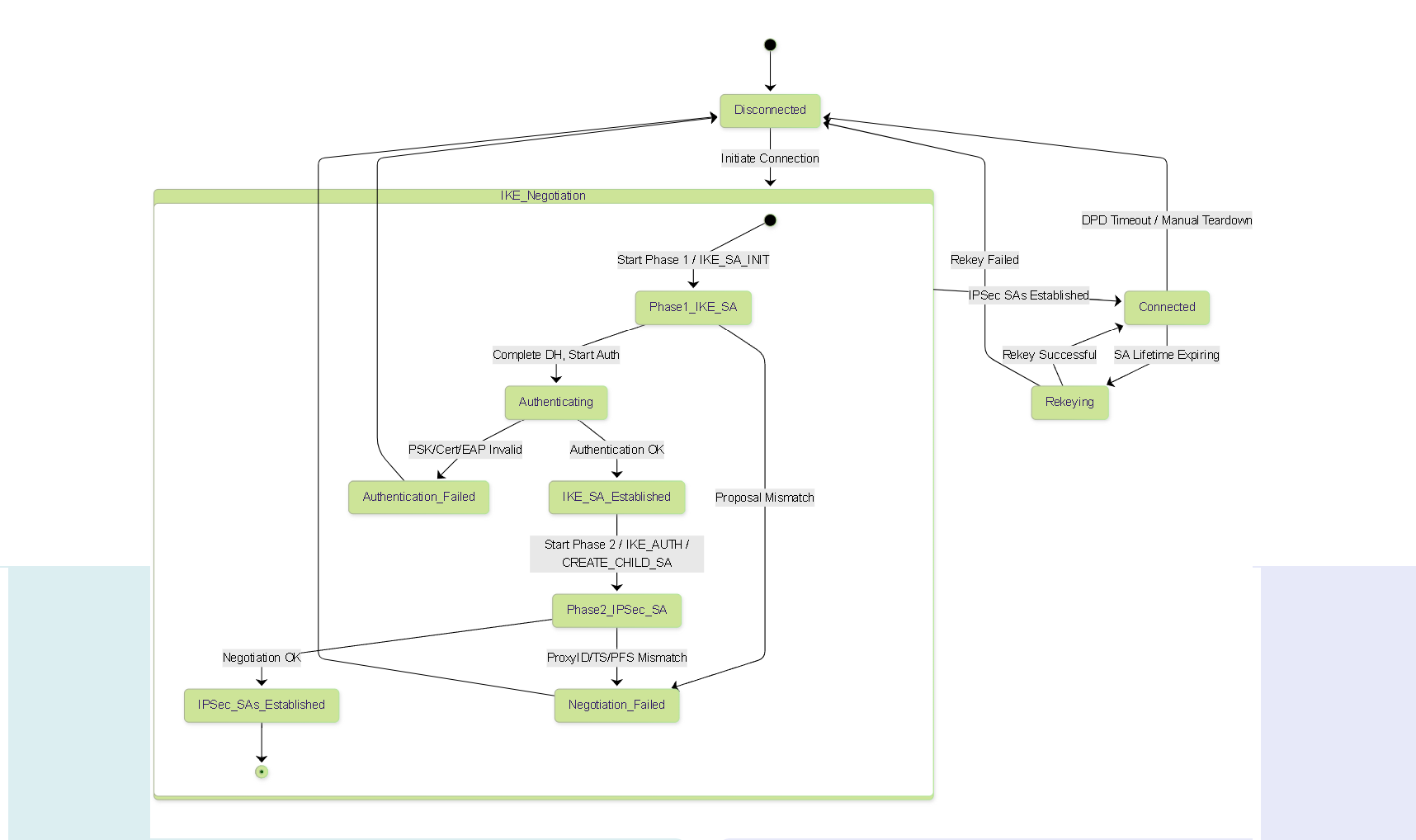
IKEv1 Details: The Original Two-Phase Protocol
IKE version 1, defined primarily in RFC 2409, established the foundational two-phase approach for IPSec negotiation. While largely superseded by IKEv2, understanding IKEv1 is important for interoperability with legacy systems and for appreciating the evolution of the protocol.
The Two Phases of IKEv1
-
Phase 1: Establish the IKE SA (ISAKMP SA)
- Goal: Create a secure, authenticated channel between the peers for protecting subsequent IKE communications (Phase 2).
- Process: Authenticate the peers (PSK or Certs) and establish shared secret keys using Diffie-Hellman.
- Result: A bidirectional IKE SA.
- Modes: Main Mode (MM) or Aggressive Mode (AM).
-
Phase 2: Establish the IPSec SAs
- Goal: Negotiate the specific parameters (protocol, algorithms, keys) for protecting the actual user data using AH or ESP.
- Process: Occurs *under the protection* of the Phase 1 IKE SA. Negotiates Traffic Selectors (Proxy IDs) defining the data flow to be protected. Can optionally perform an additional DH exchange for Perfect Forward Secrecy (PFS).
- Result: Typically two unidirectional IPSec SAs (one inbound, one outbound) for each data flow (Proxy ID pair).
- Mode: Always Quick Mode (QM).
Think of Phase 1 as building a secure phone line between the managers (IKE peers), and Phase 2 as using that secure line to agree on the specific rules (IPSec SAs) for how the workers (AH/ESP) will handle the actual cargo (user data).
Multiple Phase 2 negotiations (Quick Modes) can occur under the protection of a single Phase 1 IKE SA, establishing different IPSec SAs for different data flows or refreshing keys.
IKEv1 Phase 1 (Detailed): Establishing the IKE SA
Phase 1 creates the secure tunnel for IKE itself. It authenticates the peers and generates the keying material used to protect Phase 2 negotiations.
Common Components in Phase 1 Messages
- HDR (ISAKMP Header): Contains Initiator/Responder Cookies (used to identify the specific IKE SA state), version numbers, exchange type, flags, message ID, and length.
- SA (Security Association Payload): Carries proposals for the security parameters (encryption alg, hash alg, auth method, DH group, lifetime). Multiple transforms can be proposed.
- KE (Key Exchange Payload): Contains the Diffie-Hellman public value.
- Nonce (Nonce Payload): Contains a randomly generated number (Nonce) used to protect against replay attacks during the negotiation itself and contribute to key generation.
- ID (Identification Payload): Contains the identity of the peer (e.g., IP address, FQDN, User FQDN). Encrypted in Main Mode messages 5&6, potentially in clear/partially protected in Aggressive Mode messages 1&2.
- HASH (Hash Payload) / SIG (Signature Payload): Contains the authentication data. Calculated differently depending on the authentication method (PSK or Certificates).
Key Derivation in Phase 1
After the DH exchange (Messages 3 & 4 in MM, 1 & 2 in AM), both peers compute the same shared secret DH key (g^xy mod p). This DH key, along with the nonces and other information (like cookies and PSK/Cert data), is fed into Pseudo-Random Functions (PRFs, usually based on the negotiated hash algorithm) to derive several keying materials:
-
SKEYID: The base secret key from which others are derived. -
SKEYID_d: Used to derive keys for subsequent IPSec SAs (unless PFS is used). -
SKEYID_a: Used for authenticating IKE messages (creating the HASH/SIG payload). -
SKEYID_e: Used for encrypting IKE messages (after MM message 4 / AM message 2).
Main Mode (MM) - 6 Messages
Prioritizes identity protection.
- MM#1 (Init -> Resp): HDR, SA - Initiator proposes one or more SA parameter sets (transforms).
- MM#2 (Resp -> Init): HDR, SA - Responder selects one proposal it supports and sends it back. (Failure Point: No common proposal found).
- MM#3 (Init -> Resp): HDR, KE, Nonce - Initiator sends its DH public key and a nonce.
- MM#4 (Resp -> Init): HDR, KE, Nonce - Responder sends its DH public key and nonce. (Both sides now compute DH shared secret and derive SKEYID, SKEYID_d, SKEYID_a, SKEYID_e).
- MM#5 (Init -> Resp): HDR, IDi, HASH_I / SIG_I - Initiator sends its ID and authentication data (Hash/Signature), encrypted using SKEYID_e . HASH_I is calculated using SKEYID_a over initiator ID, responder ID, nonces, KE payloads, cookies, and SA payload.
- MM#6 (Resp -> Init): HDR, IDr, HASH_R / SIG_R - Responder verifies MM#5, then sends its ID and authentication data, also encrypted. (Failure Point: Authentication fails - PSK mismatch, invalid signature, untrusted certificate).
Result: Secure, authenticated IKE SA established.
Aggressive Mode (AM) - 3 Messages
Faster, but exposes identities earlier.
- AM#1 (Init -> Resp): HDR, SA, KE, Nonce, IDi - Initiator sends proposal, DH key, nonce, and its ID all at once. (IDi sent before encryption established).
- AM#2 (Resp -> Init): HDR, SA, KE, Nonce, IDr, HASH_R / SIG_R - Responder selects proposal, sends its DH key, nonce, ID, and authentication data. (Responder authenticates immediately. IDr and HASH_R/SIG_R sent before full encryption confirmed by initiator. Both sides compute keys after receiving KE).
- AM#3 (Init -> Resp): HDR, HASH_I / SIG_I - Initiator verifies AM#2 and sends its authentication data. (Failure Point: Authentication fails).
Result: Secure, authenticated IKE SA established, but with initial identity exposure risk.
Phase 1 Lifetimes
The IKE SA has a lifetime (negotiated in MM#1/#2 or AM#1/#2), typically specified in seconds (e.g., 28800 seconds = 8 hours). Before expiry, a rekey must occur to establish a new IKE SA. Some implementations also support data volume lifetimes (e.g., rekey after X gigabytes), but time-based is standard.
Common Phase 1 Troubleshooting Points
- No Response from Peer: Firewall rules blocking UDP 500, incorrect peer IP address, routing issues.
- Proposal Mismatch: No common set of Encryption/Hash/Auth/DH Group/Lifetime parameters found between initiator's proposal and responder's policy. Check configurations on both sides.
-
Authentication Failure:
- PSK: Keys do not match exactly (case-sensitive).
- Certificates: Invalid signature (private key doesn't match public key), certificate expired, CA not trusted by peer, Certificate Revocation List (CRL) / Online Certificate Status Protocol (OCSP) check failed, ID payload mismatch with certificate subject/SAN.
- NAT-T Issues: If NAT exists but NAT-T detection fails or is disabled/unsupported.
IKEv1 Phase 2 (Detailed): Establishing IPSec SAs (Quick Mode)
Phase 2 runs *inside* the secure tunnel created by Phase 1. Its sole purpose is to negotiate the Security Associations (IPSec SAs) used by AH or ESP to protect user data. It always uses Quick Mode (QM).
Quick Mode (QM) - 3 Messages
All QM messages are encrypted and authenticated using the keys (SKEYID_e, SKEYID_a) and algorithms established in Phase 1.
-
QM#1 (Init -> Resp): HDR*, HASH(1), SA, Ni, [KE], [IDci, IDcr]
-
HDR*: ISAKMP Header (Encrypted). Contains message ID specific to this QM exchange. -
HASH(1): Authenticates the message content, calculated using SKEYID_a. -
SA: Proposes IPSec parameters (Protocol: AH/ESP, Algorithms: Encryption/Hash, Mode: Tunnel/Transport, Lifetime). -
Ni: Initiator's nonce for this QM exchange (contributes to Phase 2 key derivation). -
[KE]: Optional. Diffie-Hellman public key payload *if* Perfect Forward Secrecy (PFS) is requested for this SA. Requires negotiation of a PFS DH Group. -
[IDci, IDcr]: Optional but CRITICAL . Identification payloads defining the **Traffic Selectors** or **Proxy IDs**.-
IDci(Initiator's Traffic Selector): Specifies the source traffic from the initiator's perspective (e.g., local subnet). -
IDcr(Responder's Traffic Selector): Specifies the destination traffic from the initiator's perspective (e.g., remote subnet). - Typically includes: ID Type (e.g., IPv4 Subnet), Protocol ID, Port, IP Subnet Address, Netmask.
-
-
-
QM#2 (Resp -> Init): HDR*, HASH(2), SA, Nr, [KE], [IDci, IDcr]
-
HASH(2): Authenticates this response message. -
SA: Responder confirms the chosen IPSec parameters. (Failure Point: No common proposal, e.g., responder doesn't support proposed ESP-AES-256). -
Nr: Responder's nonce for this QM exchange. -
[KE]: Optional. Responder's DH public key if PFS was requested in QM#1. (Failure Point: PFS DH Group mismatch). -
[IDci, IDcr]: Responder confirms the Traffic Selectors. These MUST exactly match (often inversely) the policy configured on the responder for the initiator's proposed traffic. Mismatch here is the #1 cause of Phase 2 failure. Example: Initiator sends IDci=192.168.1.0/24, IDcr=10.0.0.0/16. Responder policy must match source=10.0.0.0/16, destination=192.168.1.0/24.
After QM#2, both sides can derive the IPSec SA keys using SKEYID_d (from Phase 1) OR the new DH shared secret (if PFS is enabled), plus the QM nonces (Ni, Nr) and other parameters.
-
-
QM#3 (Init -> Resp): HDR*, HASH(3)
-
HASH(3): Acknowledges receipt and successful processing of QM#2, confirming SA establishment. Calculated over message IDs and nonces.
-
Result: Two unidirectional IPSec SAs (one inbound, one outbound) are established for the specific data flow defined by the Proxy IDs. Each SA has its own keys and sequence number counter.
Multiple Proxy IDs / SAs
If multiple network pairs need protection (e.g., subnet A to subnet X, and subnet B to subnet Y), IKEv1 generally requires a separate Quick Mode exchange for each pair of Proxy IDs. This results in multiple pairs of IPSec SAs being established under a single Phase 1 IKE SA.
Perfect Forward Secrecy (PFS) in Phase 2
If PFS is enabled (by including the KE payload in QM#1/#2), the IPSec SA keys are derived from the *new* DH exchange performed during Quick Mode, combined with nonces and potentially SKEYID_d (depending on exact derivation method). This decouples the IPSec SA keys from the original Phase 1 IKE SA keys (SKEYID_d).
- Benefit: If the long-term Phase 1 key (SKEYID or the original DH secret) is compromised *after* the Phase 2 SA is established, the data protected by that Phase 2 SA remains secure because its keys were derived independently.
- Cost: Requires an additional DH computation for every Phase 2 rekey, increasing CPU load.
- Configuration: Requires both peers to agree on enabling PFS and selecting a compatible PFS DH Group (e.g., group14, group19). Mismatch causes QM failure.
Phase 2 Lifetimes
IPSec SAs also have lifetimes, typically shorter than Phase 1 lifetimes (e.g., 3600 seconds = 1 hour). They can also have data volume lifetimes (e.g., rekey after 4GB). Before expiry, a new Quick Mode exchange (or IKEv2 CREATE_CHILD_SA) must occur to establish replacement SAs.
Common Phase 2 Troubleshooting Points
- Proxy ID / Traffic Selector Mismatch: The *most common* IKEv1 Phase 2 issue. The source/destination networks, protocols, and ports defined on the initiator must exactly match (inversely) the configuration on the responder. Check policy definitions meticulously.
- Proposal Mismatch: No common AH/ESP protocol or algorithm set found. Ensure Phase 2 proposals match on both sides.
- PFS Mismatch: One side requires PFS, the other doesn't, or they require different PFS DH groups.
- Phase 1 SA Expired/Deleted: Quick Mode cannot start if the underlying Phase 1 IKE SA is not active.
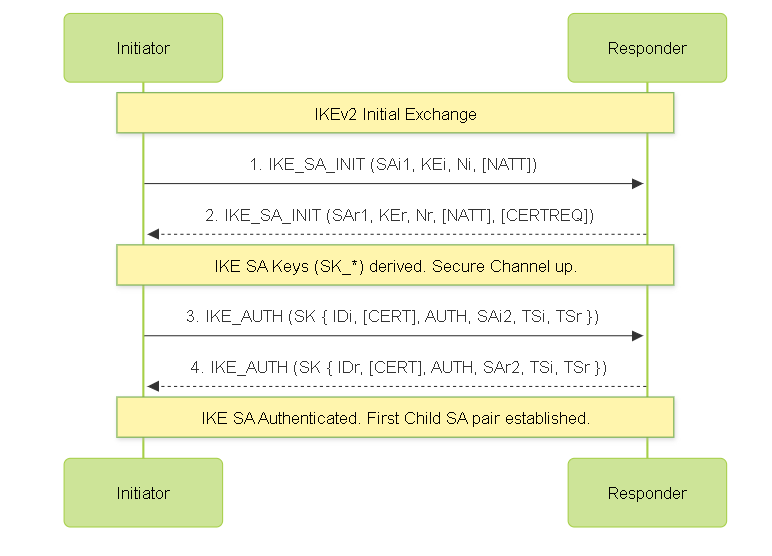
IKEv2 Details (Detailed): The Modern Standard
IKEv2 (RFC 7296) significantly streamlines and improves upon IKEv1. It uses a series of request/response pairs called Exchanges.
IKEv2 Exchanges
Instead of distinct phases and modes, IKEv2 uses specific exchanges for different tasks:
- Initial Exchanges (IKE_SA_INIT + IKE_AUTH): Establishes the IKE SA and the *first* pair of Child SAs (IPSec SAs) in just four messages. Combines the functions of IKEv1 Phase 1 and the first Phase 2.
- CREATE_CHILD_SA Exchange: Used to create additional Child SAs or to rekey the IKE SA or existing Child SAs. Runs under the protection of the IKE SA.
- INFORMATIONAL Exchange: Used for control messages like deleting SAs, reporting errors (Notify payloads), and Dead Peer Detection (DPD) keepalives.
IKEv2 Message Structure
- HDR (IKE Header): Contains Initiator/Responder SPIs (Security Parameter Index - replaces Cookies for identifying SAs), version (Major=2, Minor=0), Exchange Type, Flags (Initiator/Responder/Version bits), Message ID (sequential counter for reliability), Length.
- Payloads: Messages contain various payloads identified by a type code (e.g., SA, KE, Ni/Nr, TSi/TSr, IDi/IDr, CERT, AUTH, NOTIFY, DELETE, VENDOR_ID). Payloads are chained together using a "Next Payload" field in each payload header.
- SK {...} (Encrypted Payload): In exchanges after IKE_SA_INIT, sensitive payloads (like ID, AUTH, TS, CERT) are placed inside an Encrypted Payload (SK), which is encrypted and integrity-protected using keys derived during IKE_SA_INIT.
Initial Exchanges (4 Messages)
This is the core negotiation establishing the initial secure state.
-
IKE_SA_INIT Request (Init -> Resp): HDR, SAi1, KEi, Ni, [N(NAT_DETECTION_SOURCE_IP)], [N(NAT_DETECTION_DESTINATION_IP)], [CERTREQ]
-
SAi1: Initiator's proposals for IKE SA crypto suite (Encryption, PRF, Integrity, DH group). -
KEi: Initiator's DH public key. -
Ni: Initiator's nonce. -
N(...): Optional Notify payloads for NAT detection. Contains hashes of source/destination IPs and ports. -
[CERTREQ]: Optional request for specific types of certificates from the responder. - State Created: Minimal state created on responder before authentication (DoS improvement over IKEv1 MM).
-
-
IKE_SA_INIT Response (Resp -> Init): HDR, SAr1, KEr, Nr, [N(NAT_DETECTION_SOURCE_IP)], [N(NAT_DETECTION_DESTINATION_IP)], [CERTREQ]
-
SAr1: Responder selects one crypto suite from SAi1. (Failure: No common suite). -
KEr: Responder's DH public key. -
Nr: Responder's nonce. -
N(...): Responder sends its NAT detection hashes. (Peers compare hashes; if they differ, NAT is detected, and they switch to UDP 4500 for subsequent messages). -
[CERTREQ]: Optional responder request for certificates. -
Keys Derived:
Both sides now compute the DH shared secret and derive initial IKE SA keys (
SK_d,SK_ai,SK_ar,SK_ei,SK_er- separate keys for each direction's integrity/encryption).
-
-
IKE_AUTH Request (Init -> Resp): HDR, SK{IDi, [CERT], [CERTREQ], [IDr], AUTH, SAi2, TSi, TSr}
-
SK{...}: Entire payload block is encrypted and integrity protected using SK_ei and SK_ai. -
IDi: Initiator's identity. -
[CERT]: Optional Initiator's certificate(s). -
[CERTREQ]: Optional further certificate request. -
[IDr]: Optional assertion of expected responder identity. -
AUTH: Authentication payload. Calculated using SK_ai over the first IKE_SA_INIT message and initiator's ID/nonce data. Proves knowledge of PSK or initiator's private key (for certs), and binds identity to the key exchange. -
SAi2: Proposal for the *first Child SA* (IPSec SA - ESP/AH, algorithms, mode). -
TSi, TSr: Initiator's proposed Traffic Selectors (source and destination ranges). IKEv2 allows proposing multiple disjoint ranges within TSi/TSr, offering more flexibility than IKEv1 Proxy IDs.
-
-
IKE_AUTH Response (Resp -> Init): HDR, SK{IDr, [CERT], AUTH, SAr2, TSi, TSr, [N(...)]}
-
SK{...}: Encrypted and integrity protected using SK_er and SK_ar. -
IDr: Responder's identity. -
[CERT]: Optional Responder's certificate(s). -
AUTH: Responder's authentication payload, calculated using SK_ar over the first IKE_SA_INIT message and responder's ID/nonce data. Verifies responder's identity. (Failure: Authentication invalid). -
SAr2: Responder selects Child SA parameters from SAi2. (Failure: No common Child SA proposal). -
TSi, TSr: Responder confirms (or narrows) the Traffic Selectors. (Failure: Responder policy doesn't allow requested TS). -
[N(...)]: Optional Notify payloads (e.g., indicating use of specific features like MOBIKE). - Keys Derived: Both sides now derive keys for the established Child SA pair using SK_d and nonces.
-
CREATE_CHILD_SA Exchange (2 Messages)
Used after the initial exchange. Protected by the IKE SA keys.
- Request: HDR, SK{[N], SA, Ni, [KE], TSi, TSr} - Proposes new Child SA parameters, includes new nonces, optionally includes KE for rekeying with PFS, specifies traffic selectors. Can also be used to rekey the IKE SA itself (by omitting SA/TS payloads).
- Response: HDR, SK{[N], SA, Nr, [KE], TSi, TSr} - Responder confirms parameters, sends its nonce, optionally its KE for PFS, confirms traffic selectors. New keys are derived.
INFORMATIONAL Exchange (2 Messages)
Used for control and status. Protected by the IKE SA keys.
- Request: HDR, SK{[N], [D], [CP], ...}
- Response: HDR, SK{[N], ...}
-
Common Payloads:
-
N (Notify): Reports errors (e.g., AUTHENTICATION_FAILED, NO_PROPOSAL_CHOSEN, TS_UNACCEPTABLE), status (e.g., INITIAL_CONTACT), or used for DPD keepalives. -
D (Delete): Requests deletion of specific IKE or Child SAs. -
CP (Configuration Payload): Used to request/assign configuration attributes, like internal IP addresses for remote access clients.
-
Reliability Features
IKEv2 uses the sequential Message ID in the HDR and acknowledgments (implicit in responses) to detect lost or out-of-order messages. Implementations maintain a window of acceptable message IDs and retransmit requests if a response isn't received within a timeout period.
Common IKEv2 Troubleshooting Points
- IKE_SA_INIT Failure: No common IKE proposal (check Encryption/PRF/Integrity/DH Group). Firewall blocking UDP 500/4500.
- IKE_AUTH Failure: Authentication failure (PSK/Cert/EAP incorrect/invalid/untrusted). No common Child SA proposal. Traffic Selector (TS) mismatch (responder policy rejects proposed TSi/TSr). Identity mismatch.
- CREATE_CHILD_SA Failure: Rekey proposal mismatch, TS mismatch for new SA, PFS mismatch if enabled.
- Tunnel Drops: DPD failure (peer unresponsive), SA lifetime expiry without successful rekey.
IKEv1 vs IKEv2 Comparison (Expanded)
IKEv2 offers substantial improvements over IKEv1, making it the strongly preferred protocol.
| Feature | IKEv1 | IKEv2 |
|---|---|---|
| Negotiation Structure | Distinct Phase 1 (MM/AM) & Phase 2 (QM) | Integrated initial exchange (IKE_SA_INIT + IKE_AUTH), separate CREATE_CHILD_SA, INFORMATIONAL |
| Initial Messages | Typically 9 (6 MM + 3 QM) | Typically 4 |
| Reliability | None built-in (relies on timeouts) | Built-in (Sequence numbers, Acknowledgments, Retransmissions) |
| NAT Traversal (NAT-T) | Extension (RFC 3947), separate detection | Built-in (RFC 7296), integrated detection (NAT_DETECTION notifies) |
| Dead Peer Detection (DPD) | Extension (RFC 3706) | Built-in (Uses INFORMATIONAL exchange) |
| Mobility / Multihoming | No standard support | Standardized (MOBIKE - RFC 4555) (Uses INFORMATIONAL + CP) |
| Remote Access Authentication | PSK, Certificates, XAUTH (proprietary/draft extension for user auth) | PSK, Certificates, Standardized EAP (RFC 7296) (Flexible user/device auth) |
| Traffic Selector Negotiation | Strict matching required (Proxy IDs), 1 pair per QM | Flexible (TSi/TSr can contain multiple ranges), negotiated in IKE_AUTH / CREATE_CHILD_SA |
| Denial-of-Service (DoS) Resistance | Weaker (e.g., MM creates state before auth; AM vulnerable to PSK cracking) | Improved (Less state before auth in IKE_SA_INIT, anti-clogging cookies option, AUTH protects against PSK cracking) |
| Protocol Complexity | More modes, phases, less clear structure | Simpler, more streamlined exchanges, clearer structure |
| Resource Usage | Can be higher due to more messages | Generally more efficient |
| Extensibility | More limited | Designed for easier extension (Notify payloads, new exchanges) |
| Asymmetric Authentication | Generally not supported (peers use same method) | Supported (e.g., Initiator uses PSK, Responder uses Cert) |
IPSec Protocols (Detailed): AH & ESP Data Plane
AH and ESP are the workhorses of the IPSec data plane. They operate based on the Security Associations (SAs) established by IKE.
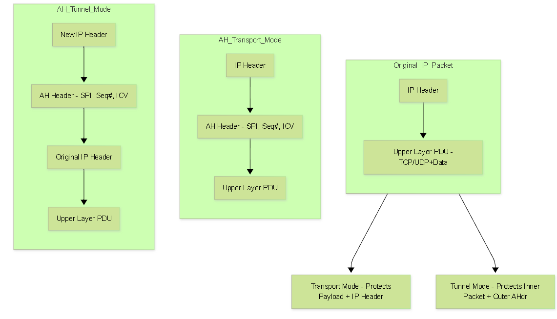
Authentication Header (AH) - IP Protocol 51
AH provides strong integrity and authentication but lacks confidentiality.
-
Services:
- Connectionless Integrity: Guarantees the packet wasn't modified in transit using an Integrity Check Value (ICV), typically an HMAC (e.g., HMAC-SHA256).
- Data Origin Authentication: Implicitly provided by the HMAC, proving the sender knew the shared secret key.
- Anti-Replay Protection: Uses a mandatory 32-bit Sequence Number field that increments for each packet. The receiver uses a sliding window to detect and discard replayed packets.
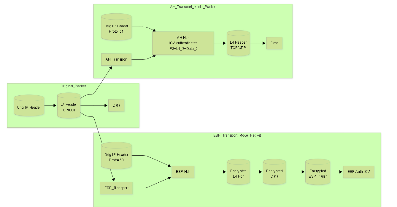
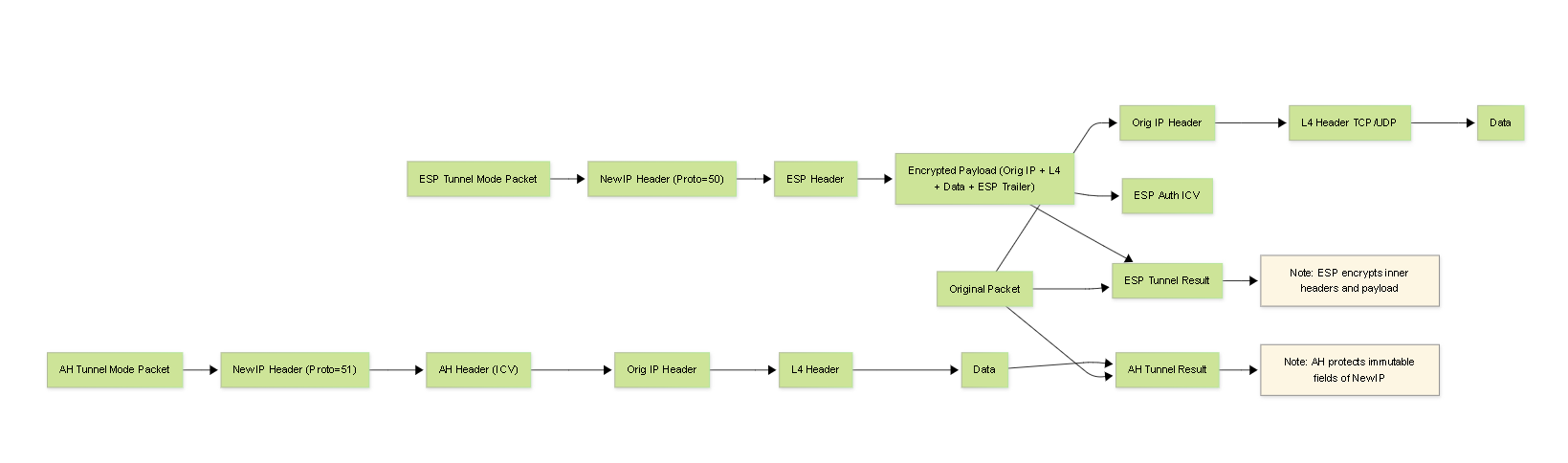
- Scope of Authentication: AH authenticates the entire IP packet , including the payload and immutable or predictably mutable fields of the IP header (e.g., Source/Destination IP, Protocol). Fields that change in transit (like TTL, DSCP, Header Checksum) are zeroed out before the ICV calculation.
- NAT Incompatibility: Because AH authenticates the IP header fields (including source IP), any modification by a NAT device will invalidate the ICV , causing the receiver to discard the packet. AH cannot be used across NAT.
-
Header Structure:
Inserted after the original IP header (Transport mode) or after the new outer IP header (Tunnel mode). Contains:
- Next Header: Identifies the protocol following AH (e.g., TCP, UDP, or the inner IP header in Tunnel mode).
- Payload Len: Length of the AH header itself.
- Reserved: Must be zero.
- Security Parameters Index (SPI): 32-bit value identifying the specific SA used for this packet.
- Sequence Number: 32-bit anti-replay counter.
- Integrity Check Value (ICV): Variable length (e.g., 12 bytes for HMAC-SHA1-96, 16 bytes for HMAC-SHA256-128). Contains the authentication digest.
Encapsulating Security Payload (ESP) - IP Protocol 50
ESP is the versatile workhorse, offering confidentiality and optional integrity/authentication.
-
Services:
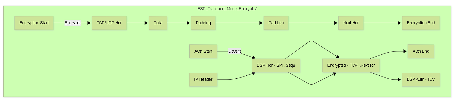
- Confidentiality (Encryption): Encrypts the protected payload using algorithms like AES or 3DES. This is ESP's primary function.
- Connectionless Integrity (Optional but Recommended): If negotiated, provides integrity for the ESP header, encrypted payload, and ESP trailer using an ICV (HMAC). Crucially, it typically does *not* include the outer IP header in the ICV calculation, enabling NAT compatibility.
- Data Origin Authentication (Optional): Provided implicitly when integrity is enabled via the HMAC.
- Anti-Replay Protection (Optional but Recommended): Uses a mandatory 32-bit Sequence Number field like AH.
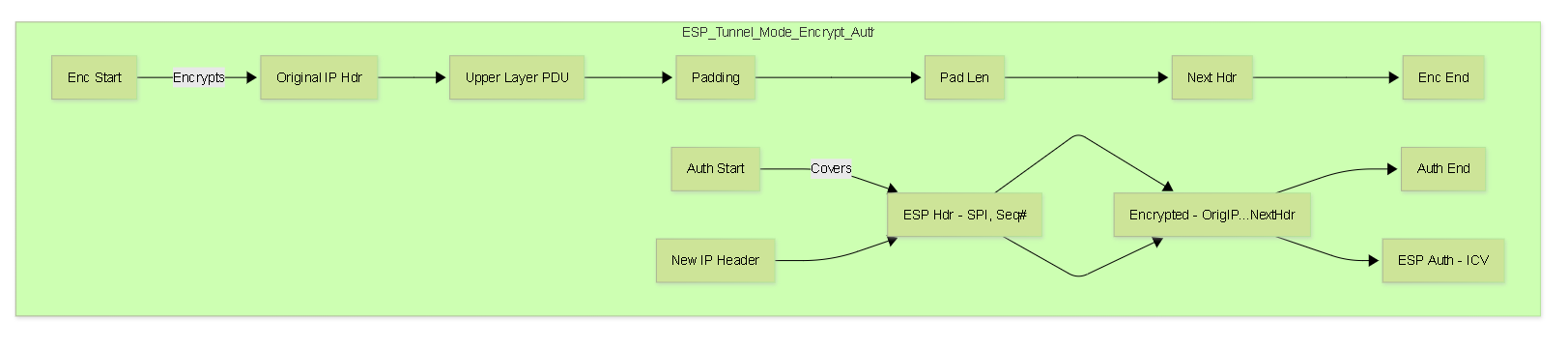
- Limited Traffic Flow Confidentiality (Tunnel Mode): By encrypting the original IP header in Tunnel Mode, ESP hides the internal source/destination IPs from eavesdroppers on the path between gateways.
-
Scope of Protection:
- Encryption: Covers the IP payload (Transport Mode) or the entire original IP packet (Tunnel Mode).
- Authentication (ICV): Covers the ESP Header, the *encrypted* payload, and the ESP Trailer (Padding, Pad Length, Next Header). Does NOT cover the outer IP header.
- NAT Compatibility (NAT-T): Because the outer IP header is not included in the standard ESP ICV calculation, NAT devices can modify it without breaking ESP integrity. For NAT traversal, ESP packets (along with IKE) are encapsulated within UDP headers (typically using destination port 4500).
-
Header/Trailer Structure:
-
ESP Header:
Inserted after the outer IP header. Contains:
- Security Parameters Index (SPI): 32-bit value identifying the SA.
- Sequence Number: 32-bit anti-replay counter.
- Encrypted Payload: The original payload (Transport Mode) or original IP packet (Tunnel Mode), encrypted.
-
ESP Trailer:
Appended after the encrypted payload. Contains:
- Padding: Added to align the payload for block ciphers or hide payload length.
- Pad Length: Specifies the length of the padding.
- Next Header: Identifies the protocol of the decrypted payload (e.g., TCP, UDP, IP).
- ESP Authentication Data (ICV): Appended after the ESP Trailer *if* authentication is enabled. Variable length (e.g., 12-16 bytes).
-
ESP Header:
Inserted after the outer IP header. Contains:
Choosing AH vs. ESP
- Need Confidentiality ? Use ESP .
- Need NAT Compatibility ? Use ESP (with NAT-T).
- Need Authentication/Integrity ? Use AH OR ESP with Authentication (Recommended) .
- Need to authenticate parts of the outer IP header and *don't* need encryption or NAT? Use AH (Rare).
In modern networks, ESP with Authentication (using strong algorithms like AES-GCM or AES-CBC + SHA-256) in Tunnel Mode is the most common and recommended configuration for VPNs.
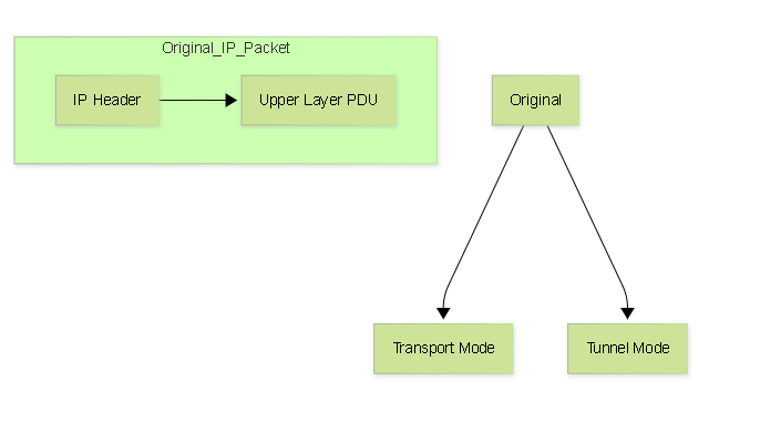
IPSec Modes (Detailed): Transport vs. Tunnel Mode
The choice between Transport and Tunnel mode dictates *how much* of the original packet is protected and *how* it's encapsulated.
Transport Mode
- Purpose: To protect the upper-layer protocols (Layer 4 payload like TCP/UDP segments) between two end hosts.
-
Encapsulation:
- The IPSec header (AH or ESP) is inserted *after* the original IP header and *before* the original Layer 4 header (TCP/UDP/ICMP etc.).
- The original IP header is retained (though potentially modified slightly, e.g., Protocol field changed to 50/51, length/checksum updated).
-
Protection Scope:
- ESP: Encrypts and optionally authenticates the Layer 4 PDU (Header + Data) and ESP trailer.
- AH: Authenticates the Layer 4 PDU and the original IP header (immutable fields).
- IP Headers: Only the original IP header exists. Source and Destination IPs remain the original communicating hosts.
- Overhead: Less overhead than Tunnel mode (no extra IP header added).
-
Use Cases:
- Securing end-to-end communication between specific hosts (e.g., client-server).
- Often used by host-based IPSec implementations.
- Used in L2TP/IPSec where L2TP provides the "tunnel" and IPSec (often ESP Transport mode) secures the L2TP packets between the client and the L2TP Network Server (LNS).
- Generally NOT used for gateway-to-gateway site-to-site VPNs.
Tunnel Mode
- Purpose: To protect IP traffic between security gateways (e.g., firewalls, routers) or between a host and a security gateway (remote access).
-
Encapsulation:
- The *entire original IP packet* (Header + Payload) is treated as the payload data.
- This original packet is encapsulated with an IPSec header (AH or ESP).
- A *new outer IP header* is added before the IPSec header.
-
Protection Scope:
- ESP: Encrypts and optionally authenticates the *entire original IP packet* plus the ESP trailer.
- AH: Authenticates the *entire original IP packet* plus the AH header and immutable fields of the *new outer IP header*.
-
IP Headers:
- Outer IP Header: Contains the source and destination IP addresses of the IPSec peers (e.g., the public IPs of the VPN gateways).
- Inner IP Header: The original packet's IP header, now part of the payload (encrypted by ESP, authenticated by AH/ESP).
- Overhead: More overhead than Transport mode due to the addition of the new outer IP header (typically 20 bytes for IPv4).
-
Use Cases:
- Site-to-Site VPNs: Standard mode for connecting networks via gateways.
- Remote Access VPNs: Connecting individual hosts to a gateway.
- Hides internal network topology from the intermediate network.
- Required when the security endpoint (gateway) is different from the communicating hosts.
IPSec Databases: SPD and SAD
The operation of IPSec relies on two key conceptual databases maintained by an IPSec implementation:
1. Security Policy Database (SPD)
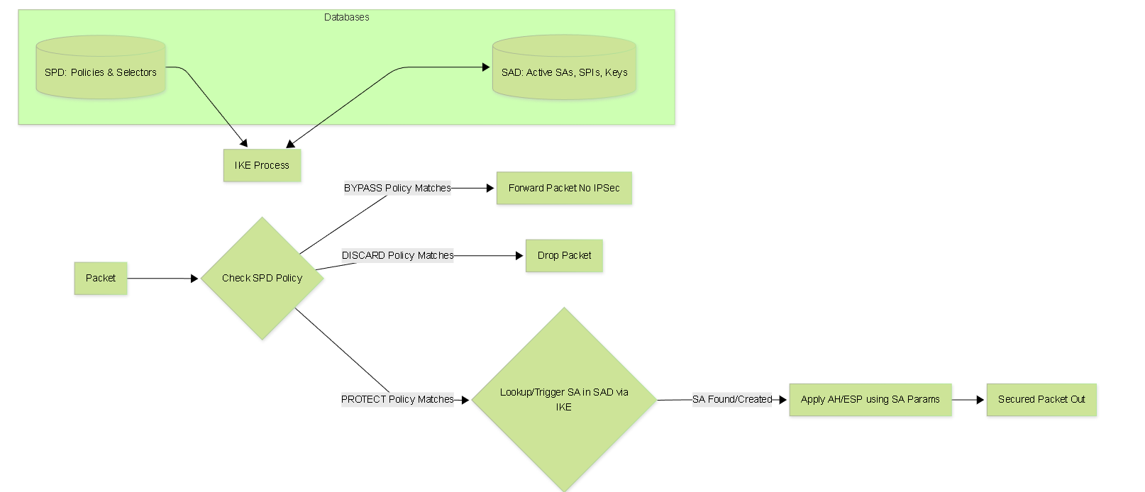
- Purpose: Defines the security policy applied to IP traffic. It acts as the primary filter determining *what* to do with a packet based on its characteristics (selectors).
-
Selectors:
Policies in the SPD match traffic based on fields like:
- Source IP Address / Subnet Mask
- Destination IP Address / Subnet Mask
- Protocol (TCP, UDP, ICMP, etc.)
- Source Port / Destination Port
- User ID / Group ID (less common in basic IPSec, more relevant with specific extensions)
- Direction (Inbound / Outbound)
-
Actions:
For each policy entry, the SPD specifies an action:
- PROTECT (or APPLY): The traffic must be secured using IPSec according to a specific SA (or trigger IKE to negotiate one if none exists). This points towards the SAD.
- BYPASS (or DISCARD): The traffic should *not* be protected by IPSec. It might be forwarded in the clear or dropped based on other firewall rules.
- DISCARD: The traffic should be dropped.
-
Interaction:
- Outbound Processing: Every outbound packet is checked against the SPD. If a PROTECT policy matches, the system looks for a suitable SA in the SAD. If no SA exists, IKE is triggered to negotiate one based on the policy's requirements. If a BYPASS or DISCARD policy matches, IPSec processing is skipped or the packet is dropped.
- Inbound Processing: Inbound packets arriving *with* IPSec protection (AH/ESP) are processed using the SA identified by the SPI (looked up in the SAD). After decryption/authentication, the inner packet *may* be re-checked against the SPD's inbound policies to ensure it's allowed. Inbound packets arriving *without* IPSec protection are checked against the SPD; if a PROTECT policy matches for that traffic type, it might be dropped (as it should have been protected). If a BYPASS policy matches, it proceeds normally.
-
Implementation:
How the SPD is configured varies greatly:
- Policy-Based VPNs: The SPD is directly configured via security policies or ACLs that explicitly define the "interesting traffic" and link it to VPN actions.
- Route-Based VPNs: The SPD often contains a very broad PROTECT policy associated with the tunnel interface (e.g., protect all traffic from 0/0 to 0/0). The *routing table* effectively acts as the primary filter *before* the SPD check for the tunnel interface itself. Traffic routed *to* the tunnel interface implicitly requires protection based on the interface's associated policy.
2. Security Association Database (SAD)
- Purpose: Stores the parameters for all active Security Associations (SAs).
-
Content:
Each entry in the SAD represents a single, unidirectional SA and contains detailed information needed to process traffic:
- Security Parameter Index (SPI): A 32-bit unique identifier for the SA, carried in the AH/ESP header. Allows the receiver to quickly find the correct SA entry.
- Destination IP Address: The endpoint of the SA (the peer's IP address).
- IPSec Protocol: AH or ESP.
- Algorithms: Specific encryption algorithm and key, authentication/integrity algorithm and key.
- Keys: The actual cryptographic keys used for encryption and/or authentication for this SA.
- SA Lifetime: Remaining time or data volume before the SA expires.
- IPSec Mode: Transport or Tunnel.
- Anti-Replay Window: Information about the sequence numbers received to prevent replay attacks.
- Selectors (from SPD): Sometimes included for reference, linking the SA back to the policy that created it.
-
Interaction:
- Outbound Processing: When the SPD indicates PROTECT, the system uses the destination address and policy selectors to find the appropriate outbound SA in the SAD. It then uses the SA's parameters (keys, algorithms, SPI, sequence number) to encapsulate/protect the packet.
- Inbound Processing: When an inbound AH or ESP packet arrives, the receiver uses the SPI from the IPSec header and the source IP address to look up the corresponding inbound SA in the SAD. It then uses the SA's parameters (keys, algorithms, anti-replay window) to decrypt and/or authenticate the packet.
- Population: The SAD is primarily populated dynamically by IKE as it successfully negotiates SAs. Manual configuration of SAs is possible but rare and complex (manual keying).
Understanding the roles of the SPD (what to protect) and SAD (how to protect it) is crucial for diagnosing many IPSec issues, especially those related to traffic not being encrypted when expected, or encrypted traffic being dropped.
IPSec Authentication Methods (Detailed)
Authenticating peers during IKE negotiation is paramount to ensure you are establishing a secure tunnel with the intended party. IKE provides several methods:
1. Pre-Shared Keys (PSK)
-
Mechanism:
A secret string (the key) is manually configured identically on both peers. During IKE authentication (MM#5/#6 or AM#2/#3 in IKEv1; IKE_AUTH in IKEv2), each peer generates an AUTH payload. This payload is typically a keyed hash (HMAC) calculated using a derived key (
SKEYID_ain IKEv1,SK_ai/SK_arin IKEv2) over important session data, including nonces and the peer's identity payload. SinceSKEYID_a(orSK_a*) is derived using the PSK, successfully validating the AUTH payload proves the other peer also possesses the correct PSK without transmitting the PSK itself. -
Identity Binding:
PSK itself doesn't strongly bind to a specific machine identity. The identity used in the negotiation is taken from the ID payload (IDi/IDr). Common ID Types used with PSK:
-
ID_IPV4_ADDR/ID_IPV6_ADDR: The peer's IP address. Simple, but problematic if IPs change or if multiple peers behind a NAT share an IP. -
ID_FQDN(Fully Qualified Domain Name): e.g., "gateway.example.com". More flexible than IP if IPs change but DNS is updated. -
ID_USER_FQDN(User FQDN): e.g., "user@example.com". Often used in remote access scenarios with PSK+XAUTH/EAP. -
ID_KEY_ID: An opaque identifier string (e.g., a site name). Useful when IP/FQDN is not suitable.
Both peers must be configured to expect the correct ID type and value from the other peer, in addition to having the matching PSK.
-
-
Security Considerations:
- Use strong, long, random PSKs . Weak keys are easily brute-forced, especially if IKEv1 Aggressive Mode is used.
- Change PSKs periodically.
- Avoid reusing the same PSK across multiple different VPN tunnels if possible.
- PSK is generally unsuitable for large-scale deployments due to management overhead and weaker identity assurance.
2. Digital Certificates (PKI)
-
Mechanism:
Relies on Public Key Infrastructure. Each peer has an X.509 certificate containing its public key and identity information (Subject Name, Subject Alternative Name - SAN), signed by a Certificate Authority (CA). Each peer also possesses the corresponding private key, kept secret. Authentication involves:
- Peers exchange certificates (often in IKE_AUTH for IKEv2, or sometimes MM#5/#6 if configured).
-
Each peer validates the received certificate:
- CA Trust: Is the issuing CA trusted? (Is the CA's root certificate installed and trusted locally?).
- Validity Period: Is the certificate currently valid (not expired, not before start date)?
- Revocation Status: Is the certificate revoked? (Checked via CRL - Certificate Revocation List, or OCSP - Online Certificate Status Protocol, if configured).
- Key Usage/EKU: Does the certificate permit its use for IPSec/IKE authentication?
- Identity Matching: Does the identity presented in the peer's ID payload (e.g., FQDN, IP address) match an identity present in the certificate's Subject Name or Subject Alternative Name (SAN) field? This is a common failure point.
- If validation passes, the AUTH payload is generated by *signing* the relevant session data (similar to PSK hash inputs) using the peer's **private key**.
- The receiving peer verifies the AUTH payload (the signature) using the **public key** extracted from the validated certificate. Successful verification proves the sender possesses the correct private key corresponding to the certificate.
- Identity Binding: Provides strong cryptographic binding between the peer's identity (in the certificate) and the key exchange process. The certificate itself acts as the identity credential. Common ID types used: IP Address, FQDN, Distinguished Name (DN from Subject), RFC822 (email address). The SAN field is often preferred for identities like FQDNs or IP addresses.
-
Security Considerations:
- Requires a robust PKI setup (CA server, certificate management processes).
- Private keys must be protected securely on each peer.
- Proper certificate validation (including revocation checking) is crucial.
- Highly scalable and provides strong authentication. Preferred for most enterprise deployments.
3. Extensible Authentication Protocol (EAP) - IKEv2 Only
- Mechanism: IKEv2 allows embedding EAP messages within the IKE_AUTH exchange (and potentially subsequent INFORMATIONAL exchanges). This essentially tunnels an EAP authentication dialogue between the IPSec client (supplicant) and the IPSec gateway (authenticator), which often acts as a pass-through or proxy to a backend authentication server (like RADIUS).
-
Process:
- Initiator (client) indicates desire to use EAP in IKE_AUTH request (usually doesn't send an AUTH payload initially).
- Responder (gateway) sends back an EAP-Request message (e.g., EAP-Identity).
- Client responds with EAP-Response (e.g., username).
- Gateway forwards this to RADIUS (if configured).
- Multiple EAP request/response rounds occur, specific to the chosen EAP method (e.g., challenge/response for MSCHAPv2, certificate exchange for EAP-TLS).
- Once EAP completes successfully, the peers derive shared EAP master session keys.
- The final IKEv2 AUTH payloads are then calculated using these EAP-derived keys, confirming successful authentication to both IKEv2 peers.
-
Common EAP Methods used with IKEv2:
- EAP-MSCHAPv2: Username/password based. Common but requires a secure outer tunnel (like PEAP or EAP-TTLS) if proxied over insecure networks (though within the encrypted IKEv2 SK payload, it's protected).
- EAP-TLS: Certificate-based authentication for *both* client and server. Very secure but requires client certificates.
- EAP-PEAP (Protected EAP): Creates a TLS tunnel first (server authenticates with cert), then runs another EAP method (like EAP-MSCHAPv2) inside the TLS tunnel. Protects user credentials.
- EAP-TTLS (Tunneled TLS): Similar to PEAP.
- Use Case: Primarily for **Remote Access VPNs**, allowing flexible user authentication using existing identity infrastructure (like Active Directory via RADIUS). The client still typically authenticates the gateway using the gateway's certificate.
Dynamic vs. Static Peer Considerations
- Static IP Peers: Any method works. PSK can be slightly more secure if tied to the known peer IP in the configuration.
-
Dynamic IP Peers (Remote Access):
- PSK (IKEv1 AM): Weakest. Relies only on the shared secret. Requires ID like FQDN/UserFQDN.
- PSK (IKEv2): Still relies on PSK, but IKEv2's AUTH mechanism offers better protection against offline cracking. Requires ID.
- Certificates: Strong. Gateway validates client cert; client validates gateway cert. Identity verified regardless of IP.
- EAP (IKEv2): Ideal for user auth. Combines strong gateway authentication (via cert) with flexible user authentication (via EAP method).
IPSec Cryptographic Algorithms (Detailed)
The strength of IPSec relies heavily on the robustness of the cryptographic algorithms negotiated by IKE. Choosing appropriate algorithms is crucial for security and performance.
1. Encryption Algorithms (Confidentiality - ESP Only)
These symmetric algorithms encrypt the data payload.
- DES (Data Encryption Standard): 56-bit key. Obsolete & Insecure. Susceptible to brute-force attacks in hours/days. DO NOT USE.
- 3DES (Triple DES): Effective key length 112 or 168 bits (depending on variant). Applies DES three times. Significantly stronger than DES but slow in software and uses a small 64-bit block size. Considered legacy, avoid for new deployments. Acceptable only where required for interoperability.
-
AES (Advanced Encryption Standard):
Current industry standard.
Symmetric block cipher with a 128-bit block size. Faster and more secure than 3DES. Widely supported by hardware acceleration (AES-NI).
-
AES-CBC (Cipher Block Chaining):
Common mode. Requires a separate integrity algorithm (like HMAC-SHA).
-
AES-128-CBC:128-bit key. Good baseline security, excellent performance. -
AES-192-CBC:192-bit key. More secure, slightly slower. -
AES-256-CBC:256-bit key. Highest security level, slightly higher overhead than AES-128.
-
-
AES-GCM (Galois/Counter Mode):
Authenticated Encryption with Associated Data (AEAD)
mode. Provides both
confidentiality and integrity/authentication
in one operation. Often faster than AES-CBC + HMAC, especially with hardware support. Considered highly secure. Available in 128, 192, 256-bit key lengths (e.g.,
AES-128-GCM,AES-256-GCM). Recommended when supported by both peers. - AES-CCM (Counter with CBC-MAC): Another AEAD mode, less common in IPSec than GCM but also secure.
-
AES-CBC (Cipher Block Chaining):
Common mode. Requires a separate integrity algorithm (like HMAC-SHA).
- NULL Encryption: Specifies no encryption. Used when ESP is desired only for authentication/integrity (though AH is often simpler for that specific case if NAT is not involved). Sometimes used during debugging.
2. Integrity / Authentication Algorithms (Hashing)
Used by AH and ESP (when authentication is enabled) to ensure data integrity and origin authentication, typically via HMAC (Keyed-Hash Message Authentication Code).
- MD5 (Message Digest 5): 128-bit hash. Obsolete & Insecure. Collision vulnerabilities are well-known. DO NOT USE (HMAC-MD5).
- SHA-1 (Secure Hash Algorithm 1): 160-bit hash. Weak & Deprecated. Collision attacks demonstrated. Being phased out globally. AVOID (HMAC-SHA1).
-
SHA-2 Family:
Current standard.
Stronger collision resistance.
-
SHA-256:256-bit hash. Good balance of security and performance. Commonly used ( HMAC-SHA256 ). -
SHA-384:384-bit hash. More secure than SHA-256. -
SHA-512:512-bit hash. Highest security in the SHA-2 family. Performance overhead might be slightly higher, especially on 32-bit platforms. - (Note: Truncated versions like SHA512/256 also exist but are less common in basic IPSec proposals).
-
- AES-XCBC-MAC: An integrity algorithm based on AES, sometimes used with ESP.
- AES-GMAC: The integrity/authentication component used within AES-GCM. Not typically selected separately.
When using ESP, always enable an integrity/authentication algorithm (or use an AEAD mode like AES-GCM). Relying on ESP for encryption only is insecure.
3. Pseudo-Random Function (PRF) Algorithms (IKE Only)
Used within IKE (especially IKEv2) to derive keying material (SKEYID, SK_*, etc.) from shared secrets (DH result, nonces, PSK). Typically based on the negotiated integrity algorithm.
- PRF_HMAC_MD5 (Insecure)
- PRF_HMAC_SHA1 (Weak)
- PRF_HMAC_SHA256 / 384 / 512 (Recommended)
- PRF_AES128_XCBC
4. Diffie-Hellman (DH) Groups (Key Exchange - IKE Only)
Determines the strength of the key exchange process used to generate shared secrets for IKE SA and optionally for IPSec SA (PFS). Higher group numbers generally offer more security but require more computation.
-
MODP (Modular Exponential) Groups:
Based on exponentiation over large prime fields.
- Group 1 (768-bit): Insecure.
- Group 2 (1024-bit): Weak/Insecure.
- Group 5 (1536-bit): Legacy, avoid if possible. Minimum acceptable for some old interoperability.
- Group 14 (2048-bit): Good Baseline. Widely supported. Minimum recommended for current security.
- Group 15 (3072-bit): Stronger. Good choice.
- Group 16 (4096-bit): Very strong.
- Groups 17 (6144-bit), 18 (8192-bit): Extremely strong, high overhead.
- Group 24 (2048-bit MODP w/ 256-bit POS): Defined for IKEv2, aligns DH strength better with AES-128. Often recommended alongside Group 14.
-
ECP (Elliptic Curve) Groups:
Based on elliptic curve cryptography. Offer equivalent security to MODP groups with much smaller key sizes, leading to significantly faster computation. Preferred for performance, especially at higher security levels.
- Group 19 (256-bit ECP): Roughly equivalent strength to 3072-bit MODP (Group 15). Excellent choice, balances security and performance.
- Group 20 (384-bit ECP): Roughly equivalent strength to 7680-bit MODP. Very strong.
- Group 21 (521-bit ECP): Roughly equivalent strength to 15360-bit MODP. Extremely strong.
- Groups 25, 26 (Brainpool ECP): Alternative standardized curves.
Recommendation Summary (Modern):
- IKE Phase 1 / IKE SA: AES-128/256 (CBC or GCM), SHA-256/384, DH Group 14/19/20.
- IPSec Phase 2 / Child SA: ESP with AES-GCM-128/256 (provides both Enc/Auth). OR ESP with AES-128/256-CBC and HMAC-SHA-256/384.
- PFS Group (if enabled): Match Phase 1 DH group or choose another strong group like 14/19/20.
- Avoid: DES, 3DES (if possible), MD5, SHA-1, DH Groups 1, 2, 5.
Ensure that the chosen algorithms are supported and configured identically (or have at least one common, acceptable proposal) on both IPSec peers.
NAT Traversal (NAT-T) Detailed
Network Address Translation (NAT), especially Port Address Translation (PAT), is ubiquitous on the internet but poses challenges for IPSec, primarily because:
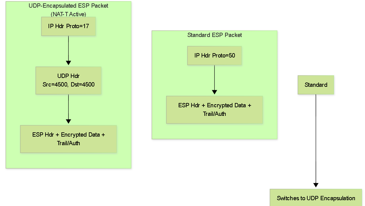
- ESP Protocol (50): Many NAT devices and firewalls are designed to handle TCP (6) and UDP (17) but may not correctly track or allow the native ESP protocol (IP Protocol 50).
- AH Protocol (51): AH authenticates the IP header, which NAT modifies (specifically the source IP/port). This inevitably breaks AH's integrity check. AH is fundamentally incompatible with NAT.
- Port Modification (PAT): NAT devices often change the source UDP port for outgoing connections to maintain unique session mappings. IKE needs to handle this potential change.
NAT Traversal (NAT-T) is the mechanism IPSec uses to overcome these issues, specifically allowing ESP to work through NAT devices.
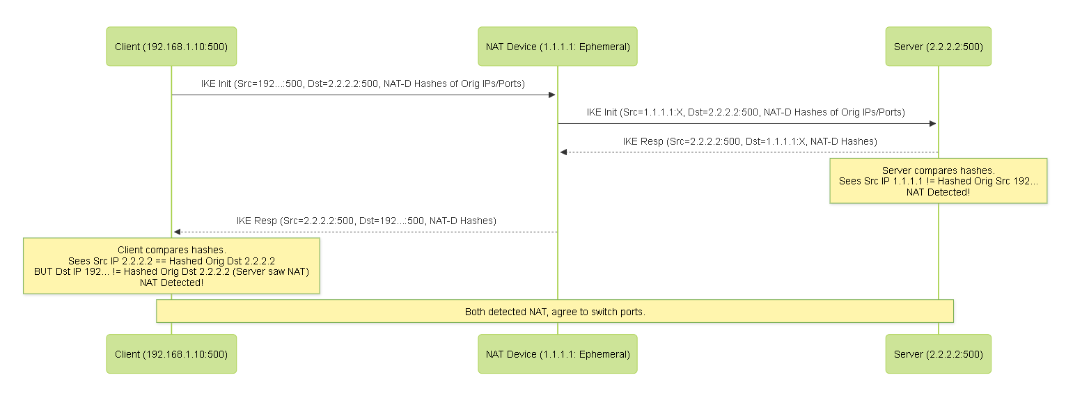
NAT-T Detection
- Mechanism: During the initial IKE exchange (IKE_SA_INIT in IKEv2, potentially vendor-specific payloads or heuristics in IKEv1), peers exchange special NAT-Detection (NAT-D) payloads.
- Payload Content: Each peer sends a hash of its *original* source IP/port and a hash of the *original* destination IP/port it intended to send to.
-
Comparison:
Upon receiving the NAT-D payloads, each peer calculates the same hashes based on the *actual* source/destination IP/port seen in the received packet's IP/UDP headers.
- If the received hashes match the locally calculated hashes, no NAT is detected between the peers for that direction.
- If the hashes *do not* match, it indicates a NAT device has modified the IP address and/or port in transit.
- Outcome: If *either* peer detects NAT, both peers agree to enable NAT-T procedures for the rest of the session.
NAT-T Encapsulation
Once NAT is detected:
- Port Change: Subsequent IKE messages are sent using UDP source and destination port 4500 instead of UDP 500. This avoids conflicts with potential OS handling of port 500 and signals NAT-T is active.
-
ESP Encapsulation:
Instead of sending ESP packets directly using IP Protocol 50, the entire ESP packet (Header + Encrypted Payload + Trailer + Auth ICV) is encapsulated within a standard
UDP header using source and destination port 4500
.
- NAT Device Handling: NAT devices see standard UDP/4500 traffic, which they can translate and forward correctly just like any other UDP session.
- Keepalives: To maintain the NAT mapping (which might time out due to inactivity), peers often send periodic NAT-T keepalive packets (small UDP packets on port 4500, often just a single 0xFF byte payload). This is separate from IKE DPD keepalives.
Considerations
- NAT-T must be supported and enabled on *both* peers.
- Firewalls between the peers must allow UDP traffic on ports 500 and 4500.
- Adds a small overhead (UDP header size - 8 bytes) to each data packet.
- Essential for almost all remote access VPNs and many site-to-site VPNs where one or both peers are behind a NAT device.
Legacy Policy-Based VPN (Detailed)
Policy-Based VPNs tie the IPSec processing directly to specific security policy rules or Access Control Lists (ACLs). The policy itself defines what traffic is "interesting" and triggers the VPN.
Mechanism of Operation
-
Configuration:
The administrator defines crypto maps (Cisco) or policy entries (other vendors) that specify:
- Interesting Traffic: An ACL or rule matching Source IP/Subnet, Destination IP/Subnet, Protocol/Port.
- Peer Identity: The IP address of the remote VPN gateway.
- IPSec Parameters: The IKE (Phase 1) and IPSec (Phase 2) proposals (algorithms, lifetimes, PFS settings) to use for traffic matching this rule.
- Authentication: The PSK or Certificate configuration associated with this peer/policy.
-
Outbound Traffic Flow:
- A packet arrives at the gateway's ingress interface.
- It's checked against the crypto map/policy list bound to the egress interface.
-
If the packet matches the "interesting traffic" definition of a policy entry:
- The gateway checks if an existing IPSec SA (Phase 2) corresponding to the *exact* traffic selectors defined in the policy already exists in the SAD.
- If an SA exists, the packet is encrypted/authenticated using that SA and sent to the peer.
- If no SA exists, the gateway initiates IKE negotiation (Phase 1 if needed, then Phase 2 Quick Mode). Crucially, the Source/Destination networks from the matching policy rule are used as the proposed Proxy IDs (IDci/IDcr) in the Quick Mode negotiation.
- Once the Phase 2 SA is established, the packet (and subsequent matching packets) are processed.
- If the packet does *not* match any VPN policy, it's processed normally (e.g., forwarded in clear, dropped by other firewall rules).
-
Inbound Traffic Flow:
- An encrypted packet arrives from the peer.
- The gateway uses the SPI in the ESP/AH header to look up the corresponding inbound SA in the SAD.
- The packet is decrypted/authenticated.
- The decrypted inner packet's source/destination IPs are checked against the "interesting traffic" definition (in reverse) associated with the SA used. If they don't match the expected Proxy IDs for that SA, the packet may be dropped.
- The decrypted packet is then typically injected back into the normal firewall policy engine for further inspection.
Proxy IDs / Traffic Selectors
This is the Achilles' heel of policy-based VPNs.
- Each policy entry defines a specific pair of source/destination networks (and potentially protocols/ports).
- This pair becomes a single Proxy ID pair negotiated in Quick Mode.
-
Example: Policy allows 192.168.1.0/24 to talk to 10.10.10.0/24.
- Initiator proposes QM with: IDci = 192.168.1.0/24, IDcr = 10.10.10.0/24.
- Responder *must* have a policy configured that exactly matches (in reverse): Local Network = 10.10.10.0/24, Remote Network = 192.168.1.0/24.
- Any mismatch in subnet address, mask, protocol, or port will cause the Phase 2 negotiation to fail for that specific flow.
- If multiple network pairs need protection (e.g., A->X, A->Y, B->X), each requires a separate policy entry and results in a separate pair of IPSec SAs being negotiated.
Limitations
- Scalability: Managing numerous policy entries and ensuring exact Proxy ID matches across peers becomes extremely complex and error-prone as the number of protected subnets grows.
- Flexibility: Adding a new subnet requires configuration changes and policy updates on *both* VPN gateways.
- Dynamic Routing: Generally incompatible. There is no virtual interface to run routing protocols over. Traffic forwarding relies solely on policy matching, not routing lookups for VPN traffic.
- Overlapping Subnets: Very difficult to handle scenarios where the same subnet exists behind different peers, as policies rely on specific IP matches.
- Troubleshooting: Often involves meticulously comparing policy definitions and Proxy IDs proposed/received in IKE debug logs.
While functional for simple scenarios, the rigidity and management overhead led to the development of route-based VPNs.
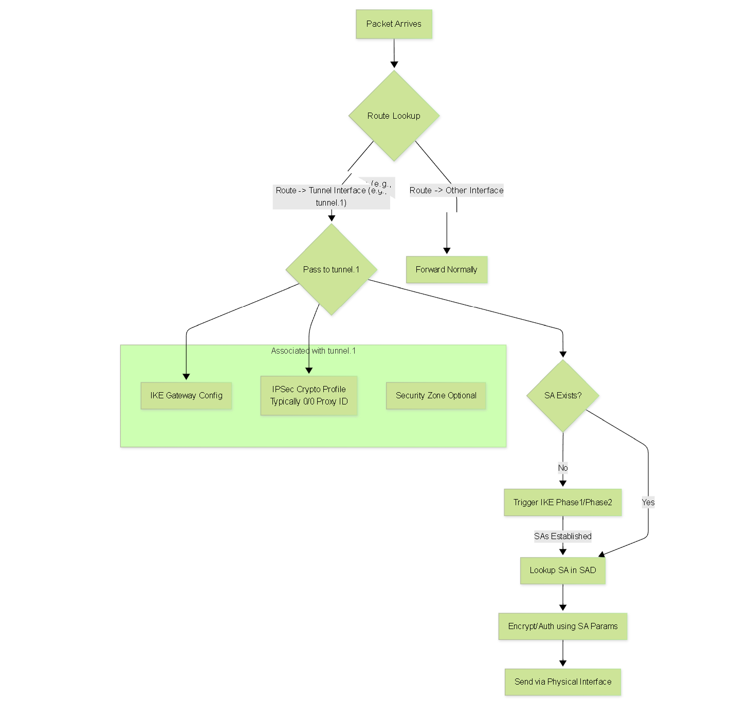
Modern Route-Based VPN (Detailed)
Route-Based VPNs decouple IPSec processing from specific traffic-matching policies by introducing a logical Tunnel Interface. This approach leverages the device's standard routing capabilities.
Mechanism of Operation
-
Configuration:
- Tunnel Interface Creation: A logical interface (e.g., `tunnel.1`, `st0.0`, `Virtual Tunnel Interface 1`) is created. This interface often has an IP address assigned (especially if running dynamic routing) but can sometimes be unnumbered.
- IKE Gateway / Peer Definition: Defines the remote peer's IP address, authentication method (PSK/Cert), and IKE (Phase 1 / IKE SA) proposals.
- IPSec Crypto Profile / Policy: Defines the IPSec (Phase 2 / Child SA) proposals (ESP/AH, algorithms, lifetime, PFS).
- Binding: The IKE Gateway and IPSec Crypto Profile are bound to the logical Tunnel Interface. This tells the interface *how* to protect traffic sent through it.
- Routing: Static routes or dynamic routing protocols (OSPF, BGP) are configured to direct traffic destined for the remote protected networks *towards the Tunnel Interface* as the next hop or egress interface.
-
Outbound Traffic Flow:
- A packet arrives at the gateway's ingress interface.
- A route lookup is performed in the main routing table based on the packet's destination IP address.
-
If the winning route points to the logical Tunnel Interface:
- The packet is logically passed to the Tunnel Interface.
-
The Tunnel Interface triggers IKE negotiation (if SAs aren't already up) using the IKE Gateway and IPSec Profile bound to it.
- Proxy ID/TS Negotiation: Typically, route-based VPNs are configured to propose very broad Traffic Selectors (e.g., source=0.0.0.0/0, destination=0.0.0.0/0, protocol=any) during the Child SA negotiation. This simplifies negotiation as the specific traffic has already been selected by the routing decision. Both peers just need to agree on these wide selectors.
- Once the necessary SAs exist (looked up in SAD via internal mapping associated with the Tunnel Interface), the packet is encrypted/authenticated using the SA parameters.
- The resulting IPSec packet (with the new outer IP header containing the gateway IPs) is handed back to the forwarding engine to be sent out the physical interface towards the peer.
- If the route lookup points elsewhere (e.g., default route to internet, another internal network), the packet bypasses the Tunnel Interface and follows that route.
-
Inbound Traffic Flow:
- An encrypted packet arrives at the physical interface.
- The gateway identifies it as IPSec traffic destined for itself (based on outer IP header + protocol 50/51 or UDP 4500).
- It uses the SPI to find the inbound SA in the SAD and decrypts/authenticates the packet.
- The original inner packet is extracted.
- This decrypted packet is then injected back into the routing engine as if it arrived on the logical Tunnel Interface .
- A new route lookup is performed on the inner packet's destination IP to determine where to forward it within the local network.
- Standard firewall policies are typically applied to traffic entering/leaving the Tunnel Interface zone.
Advantages
- Flexibility & Scalability: Adding/removing networks only requires routing updates, not IPSec configuration changes. Handles complex topologies easily.
- Dynamic Routing Support: Seamlessly integrates with OSPF, BGP, RIP allowing automatic route exchange and failover across the VPN.
- Simplified IKE Negotiation: Using broad (0.0.0.0/0) Traffic Selectors drastically reduces Phase 2 / Child SA negotiation failures due to mismatch.
- Operational Consistency: Treats VPN connectivity like any other routed path, simplifying administration and monitoring using standard routing tools.
- Easier Troubleshooting: Problems often isolate to routing issues (is the route pointing to the tunnel?) or basic IKE/SA establishment (is the tunnel interface up?), rather than complex Proxy ID mismatches.
Considerations
- Requires understanding of IP routing.
- Firewall policy might be needed specifically for traffic entering/leaving the Tunnel Interface's security zone.
- Initial setup involves creating the tunnel interface and binding policies.
Route-based VPN is the overwhelmingly preferred method for modern IPSec deployments due to its superior flexibility and integration.
Policy-Based vs. Route-Based VPN Comparison (Expanded)
Choosing between policy-based and route-based fundamentally changes how you configure, manage, and troubleshoot IPSec VPNs.
| Feature | Policy-Based VPN | Route-Based VPN |
|---|---|---|
| Decision Maker for Encryption | Security Policy / ACL match | Route Lookup result pointing to Tunnel Interface |
| Configuration Focus | Linking Crypto Maps/Policies to ACLs/Rules | Creating Tunnel Interface, Binding IKE/IPSec Profiles, **Configuring Routes** |
| Traffic Selectors / Proxy IDs | Specific (Subnets from policy), Must match exactly | Typically Broad (0.0.0.0/0 Any) , simplified negotiation |
| Adding New Protected Subnet | Modify policy/ACL on BOTH peers, triggers Phase 2 rekey for that flow | Update routing table (static/dynamic) on one or both peers as needed. **No IPSec config change.** |
| Dynamic Routing (OSPF, BGP, etc.) | Not Supported over the tunnel | Supported (Protocols run over the Tunnel Interface) |
| Virtual Interface | No routable tunnel interface | Yes (VTI, st0, tunnel.x) - Acts as a logical Layer 3 interface |
| Firewall Policy Interaction | VPN policy often processed early; decrypted traffic re-enters policy engine | Treats Tunnel Interface as a zone/interface; requires rules for traffic entering/leaving tunnel zone |
| Complexity with Many Subnets | High (many policies, risk of Proxy ID mismatch) | Low (IPSec config stable, complexity moves to standard routing) |
| Troubleshooting Focus | Policy/ACL matching, **Proxy ID mismatches**, Phase 1/2 proposal mismatches | **Routing table**, Tunnel Interface status, Phase 1/Child SA status, Zone policies |
| Use Case Fit | Simple, static peer connections; Legacy interoperability | **Most modern VPNs**, dynamic environments, complex networks, requires routing protocols |
Common IPSec Troubleshooting Scenarios
IPSec VPNs can fail at various stages. Understanding common failure points helps diagnose issues faster. Debug logs from the IKE process are essential.
Phase 1 / IKE SA Failures
- Symptom: Tunnel doesn't come up at all, no Phase 2 attempts seen. Logs show Phase 1 errors.
-
Common Causes & Checks:
-
Connectivity:
- Can peers ping each other's public IPs?
- Are UDP ports 500 and 4500 allowed by intermediate firewalls/ACLs?
- Is routing correct to reach the peer's public IP?
-
IKE Peer Definition:
- Is the remote peer IP address configured correctly?
- Is the correct local interface specified for the VPN?
-
Phase 1 Proposal Mismatch:
- Do Encryption algorithms match (e.g., AES-256 vs AES-128)?
- Do Hash algorithms match (e.g., SHA256 vs SHA1)?
- Do Diffie-Hellman groups match (e.g., Group 14 vs Group 19)?
- Do Authentication methods match (PSK vs Cert)?
- Do Lifetimes match (or are within acceptable range if negotiation allowed)?
- Look for "No proposal chosen" or similar errors in logs. Ensure *at least one* identical proposal exists on both sides.
-
Authentication Failure:
- PSK: Keys do not match *exactly* (case-sensitive, no extra spaces).
- Certificates: Is the peer's certificate valid (dates, usage)? Is the issuing CA trusted locally? Is revocation checking (CRL/OCSP) succeeding? Does the Peer ID specified in config match the Subject/SAN in the peer's certificate? Is the peer sending the correct certificate?
- Look for "Authentication failed", "Invalid KEY_ID", "Invalid Signature", "Certificate validation failed" errors.
-
IKE ID Mismatch:
- Is the local ID configured correctly (e.g., local public IP, FQDN)?
- Is the remote ID configured correctly to match what the peer is sending? (Check peer config or logs).
-
NAT-T Issues:
- Is NAT-T enabled on both sides if NAT is present?
- Is UDP 4500 blocked?
- IKE Version Mismatch: One peer trying IKEv1, the other IKEv2.
-
Connectivity:
Phase 2 / Child SA Failures
- Symptom: Phase 1 completes successfully (IKE SA is UP), but tunnel fails to pass traffic or logs show Phase 2 errors.
-
Common Causes & Checks:
-
Proxy ID / Traffic Selector Mismatch (ESPECIALLY IKEv1/Policy-Based):
- The Local/Remote networks (IP, mask, protocol, port) defined on one side do not *exactly invert* the definition on the other side.
- Look for "Proxy ID mismatch", "TS unacceptable", "No policy found" errors related to Phase 2 / Quick Mode / Child SA. Meticulously compare configurations.
- For Route-Based, ensure both sides are configured for broad selectors (e.g., 0.0.0.0/0 any) if intended.
-
Phase 2 Proposal Mismatch:
- Do IPSec protocols match (ESP vs AH)?
- Do Encryption algorithms match?
- Do Authentication/Hash algorithms match?
- Do Lifetimes match?
- Look for "No proposal chosen" errors during Phase 2 / Child SA negotiation.
-
PFS Mismatch:
- Is PFS enabled on one side but not the other?
- Do the configured PFS DH groups match?
- Look for PFS related errors in Phase 2 logs.
-
Routing Issues (Route-Based VPN):
- Is there a route pointing traffic destined for the remote network *towards the tunnel interface*?
- Is there a route on the remote peer pointing traffic back towards the local network via *its* tunnel interface?
- Is dynamic routing (if used) establishing adjacency and exchanging routes correctly over the tunnel?
-
Firewall Policy Issues:
- Are firewall rules allowing the interesting traffic *to reach* the VPN process (before encryption)?
- Are firewall rules allowing the decrypted traffic *to leave* the VPN process and reach the internal destination? (Especially relevant for route-based VPNs with tunnel zones).
- Are firewall rules on the *remote* peer allowing the traffic?
-
Proxy ID / Traffic Selector Mismatch (ESPECIALLY IKEv1/Policy-Based):
Tunnel Up, But Traffic Issues
- Symptom: IKE SAs and Child SAs show as established and UP, but specific applications or hosts cannot communicate.
-
Common Causes & Checks:
- Routing: Missing or incorrect routes on endpoints, intermediate routers, or the VPN gateways themselves (especially return routes).
- Firewall Policies: Rules on the gateways or end hosts blocking the specific traffic (ports/protocols) even after decryption. Check zones associated with tunnel interfaces.
- NAT Issues (Hairpinning/U-Turn): If trying to route traffic from one VPN spoke site to another VPN spoke site via the central hub, ensure the hub firewall allows this and handles NAT correctly if applicable ("NAT Hairpinning" or "U-Turn NAT").
- Asymmetric Routing: Traffic going out via the tunnel but return traffic trying to come back via a different path (e.g., the internet) and being blocked.
- MTU Issues: IPSec adds overhead. If Path MTU Discovery (PMTUD) is blocked or fails, large packets might be fragmented or dropped. Try lowering the TCP MSS (Maximum Segment Size) on the tunnel interface or enabling MSS clamping. Standard MTU issue symptoms (small pings work, large pings fail, TCP connections hang).
- Application Level Issues: The application itself might have problems unrelated to the VPN.
Systematic troubleshooting is key: Verify Layer 1/2/3 connectivity first, then check IKE Phase 1, then IKE Phase 2 / Child SA, then routing, then firewall policies, then MTU/MSS.
IPSec Comprehensive Quiz
Test your understanding of the detailed IPSec concepts covered in this article. Select the best answer for each question.