PAN-OS: Configuring Transparent Proxy

Transparent Proxy Overview

With transparent proxy, the client browser is not aware of the proxy's existence. Traffic is intercepted and redirected to the proxy based on network configuration (specifically NAT policies on the firewall).

This mode supports inline firewall deployments but does not support WCCP (Web Cache Communication Protocol). Authentication is typically not performed directly by the transparent proxy itself in this mode, as the client isn't configured to interact with it for authentication.

While PAN-OS can achieve transparent interception and inspection, it differs from traditional dedicated transparent proxy appliances. The PAN-OS approach relies on policy-based interception (NAT, Security, Decryption) rather than a specific "proxy mode" setting for traffic flow itself, although specific proxy *features* are enabled under Network > Proxy .

Configuration Steps for Transparent Proxy

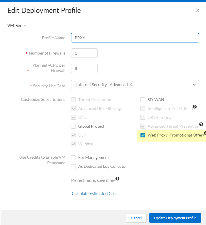
  1. License Activation (VM-Series, PA-1400, PA-3400):

    For specific models like VM-Series, PA-1400, and PA-3400, the web proxy feature requires license activation.

    • VM-Series: Log in to the Customer Support Portal (CSP), edit the relevant deployment profile, select Web Proxy (Promotional Offer) or the appropriate license, and click Update Deployment Profile .
    • CSP Deployment Profile showing Web Proxy option
    • On the firewall, retrieve the license keys from the server ( Device > Licenses > Retrieve license keys from license server ). Restart if retrieval fails initially.
    • PA-1400/PA-3400: Follow standard subscription license activation steps ( Activate Subscription Licenses ).
  2. Set Up Interfaces and Zones:

    Configure the necessary interfaces. Best practice is to use Layer 3 interfaces, each in its own zone within the same virtual router.

    • Client Interface: Interface facing the clients whose traffic will be proxied (e.g., ethernet1/1 in zone Trust ).
    • Internet Interface: Interface facing the internet/external network (e.g., ethernet1/2 in zone Untrust ).
    • Proxy Loopback Interface: Configure a dedicated Loopback interface (e.g., loopback.1 ). Assign it an IP address (e.g., 192.168.254.254/32 ) and place it in its own zone (e.g., Proxy-Zone ) within the same virtual router as the client and internet interfaces. This loopback IP is where client traffic will be redirected via NAT. Note down this IP address.
  3. Set Up DNS Proxy:

    Configure DNS Proxy to handle DNS requests intercepted by the proxy function.

    • Configure a DNS Proxy Object ( Network > DNS Proxy ). Enable it on the interface facing the clients (e.g., ethernet1/1 ).
    • Configure a DNS Server Profile ( Device > Server Profiles > DNS ) specifying Primary and Secondary DNS servers.
    • (Note: While the text mentions specifying the loopback interface for the proxy connection in DNS setup, typically DNS Proxy is enabled on the client-facing interface, and the firewall uses its standard routing/Service Routes to reach external DNS servers).

    Ensure reliable DNS resolution is available for the firewall.

  4. (Optional) Certificate Setup for Decryption:

    If you intend to decrypt HTTPS traffic intercepted by the transparent proxy (which is essential for full visibility), configure SSL Forward Proxy. This involves generating/importing a Forward Trust CA certificate and deploying it to clients. Refer to SSL Forward Proxy documentation for details.

    (See Create a Self-Signed Root CA Certificate or use an Enterprise CA).

  5. Enable Transparent Proxy Mode:

    • Navigate to Network > Proxy .
    • Click Edit for Proxy Enablement .
    • Select Transparent Proxy as the Proxy Type .
    • Click OK .
    Proxy Enablement showing Transparent Proxy selected

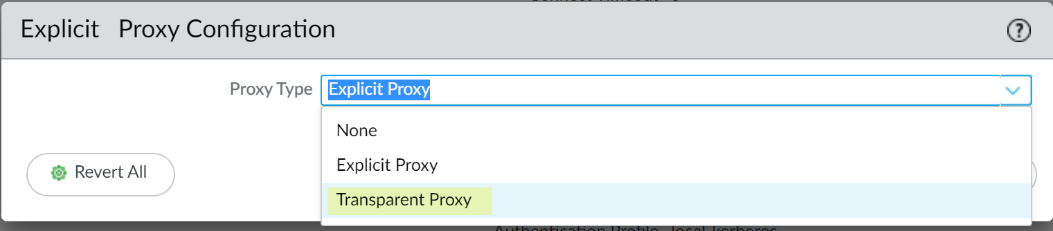
    If 'Transparent Proxy' is not an option, verify the license activation (Step 1).
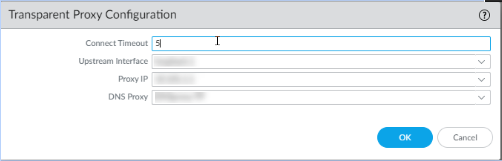
    • Click Edit for Transparent Proxy Configuration .
    • Transparent Proxy Configuration dialog box
    • Specify the Connect Timeout (seconds the proxy waits for server response, default usually fine).
    • Select the Upstream Interface : Choose the dedicated Loopback interface created in Step 2 (e.g., loopback.1 ).
    • Enter the IP address of the loopback interface as the Proxy IP .
    • Select the DNS Proxy object created in Step 3.
    • Click OK .
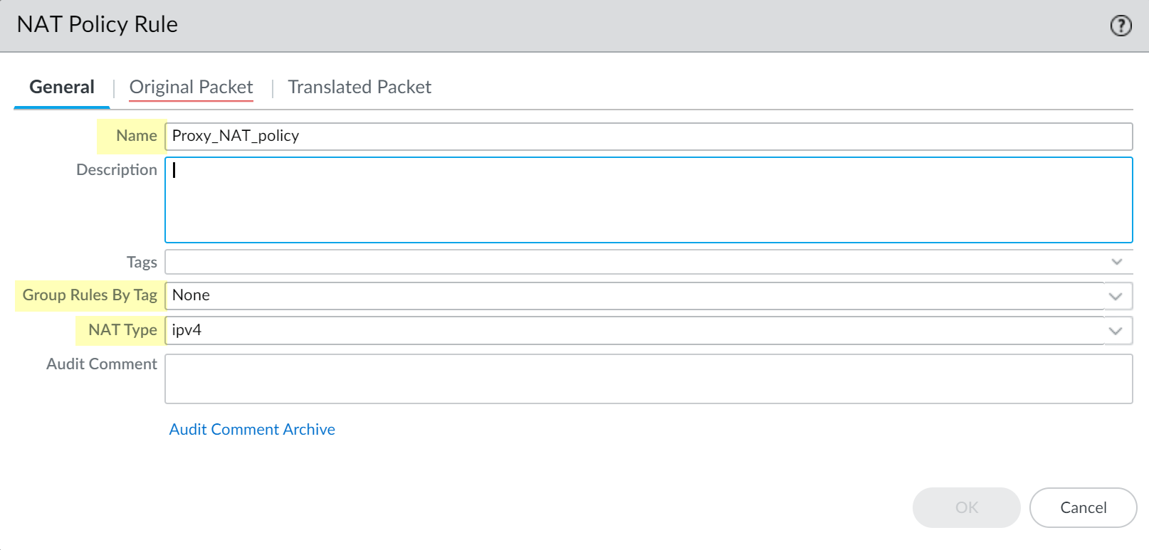
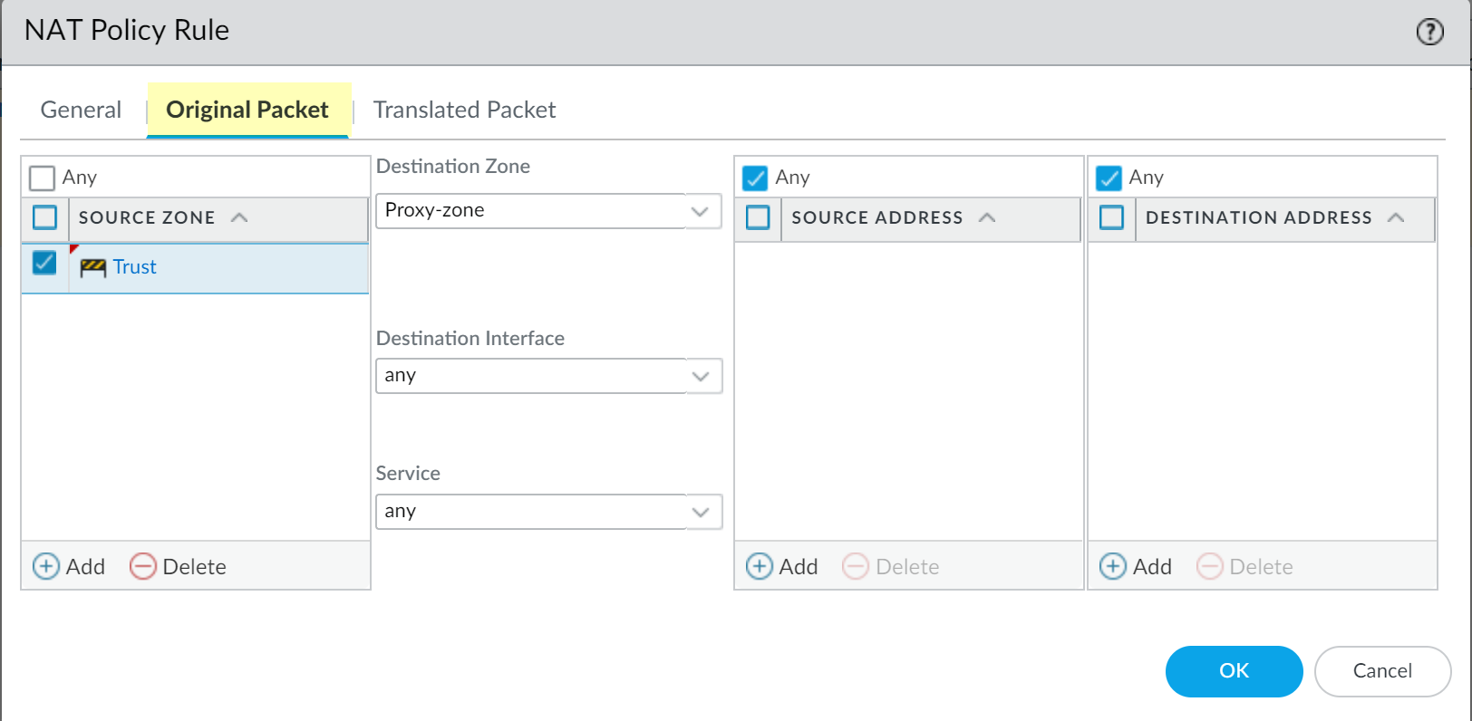
  6. Configure Destination NAT (DNAT) Policy (CRITICAL):

    This rule redirects the client's original web request (port 80/443) to the proxy loopback interface.

    • Navigate to Policies > NAT and Add a NAT rule.
    • Place this rule before any general outbound Source NAT (SNAT) rules.
    • NAT Policy Rule General Tab
    • Original Packet Tab:
      • Source Zone: Zone containing clients (e.g., Trust ).
      • Destination Zone: Zone facing the internet (e.g., Untrust ).
      • Destination Interface: Any (or specific external interface).
      • Service: Typically service-http and service-https (or a service group containing TCP/80, TCP/443).
      • Destination Address: Any (or specific external destinations if limiting scope).
    • NAT Policy Rule Original Packet Tab
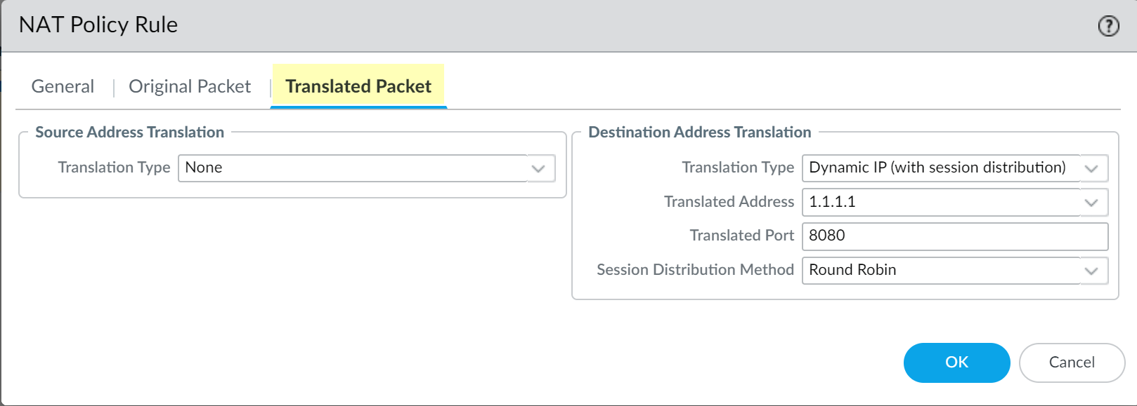
    • Translated Packet Tab:
      • Source Address Translation: Set Type to None (No SNAT in this rule).
      • Destination Address Translation:
        • Set Translation Type to Dynamic IP (with session distribution) (or Static IP if preferred, DIPP generally suitable here).
        • Set Translated Address to the IP address of the Proxy Loopback interface (e.g., 192.168.254.254 ).
        • Set Translated Port to the port the transparent proxy listener expects (typically 8080 ).
        • Session Distribution: Can usually be left as default (e.g., Round Robin - not strictly applicable here but required field).
    • NAT Policy Rule Translated Packet Tab
    • Click OK .
  7. Configure Supporting Security Policies:

    Multiple rules are needed to allow the complete flow:

    • Client to Proxy Zone: Allow traffic from the client zone (e.g., `Trust`) to the Proxy Loopback zone (`Proxy-Zone`) for destination port 8080 (or the configured proxy port). Apply relevant Security Profiles here for initial inspection before traffic leaves the firewall.
    • Proxy Zone to Internet: Allow traffic originating from the Proxy Loopback zone (`Proxy-Zone`) to the internet zone (`Untrust`). Apply necessary Security Profiles (URL Filtering, Threat Prevention, etc.) here for outbound inspection.
    • DNS Access: Ensure both clients (via DNS Proxy) and the firewall itself (potentially via the Proxy Loopback interface or another Service Route) can reach necessary DNS servers.
  8. Configure Source NAT (SNAT) Policy:

    • Create a standard outbound SNAT rule (placed *after* the DNAT rule) to translate traffic originating from the Proxy Loopback zone going to the internet (`Untrust` zone) to use an appropriate external IP address (e.g., the firewall's external interface IP).
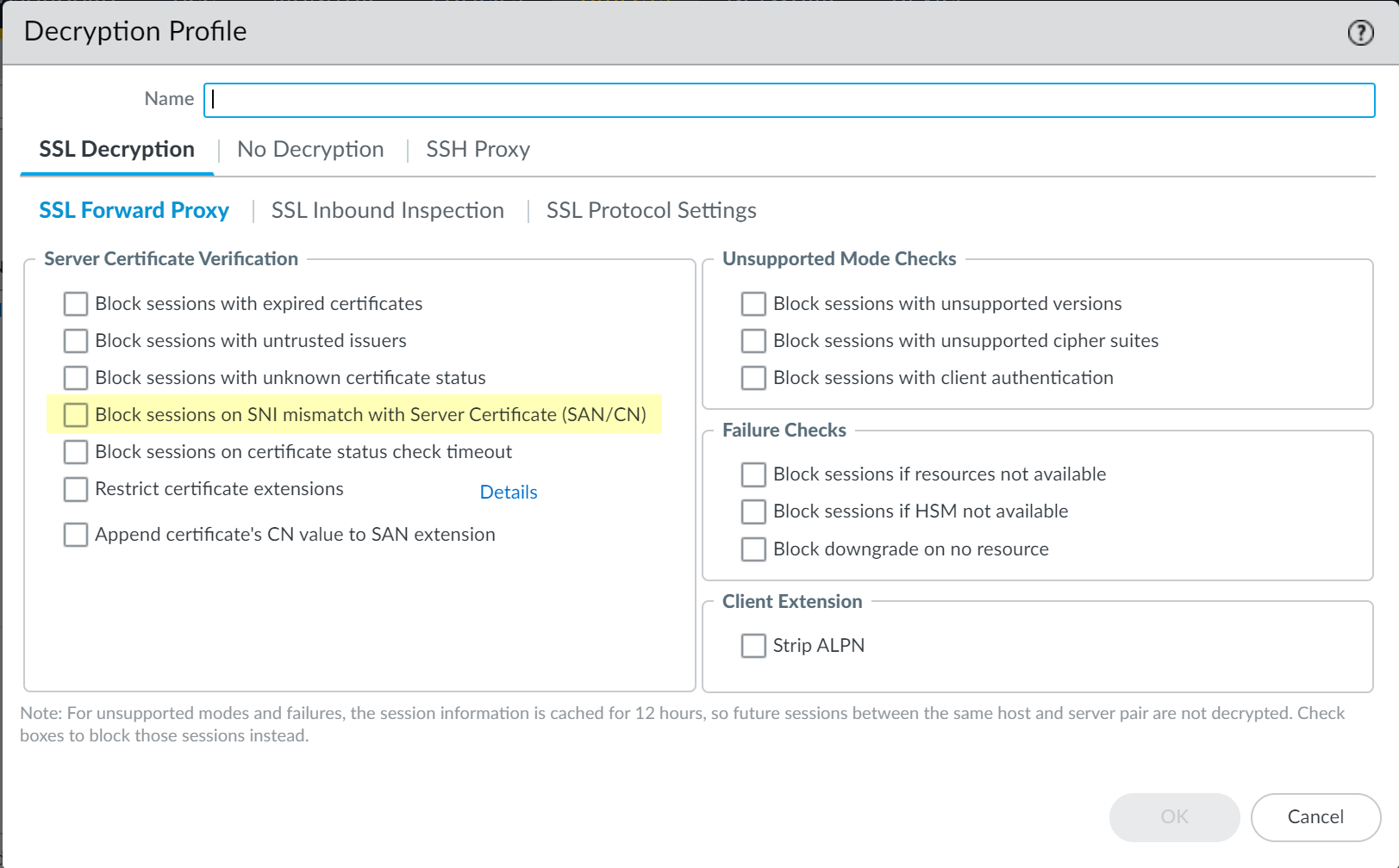
  9. (Optional) Configure Decryption Policy:

    • If inspecting HTTPS, create Decryption Policy rules (as described in SSL Forward Proxy documentation) matching traffic from the client zone (`Trust`) to the internet zone (`Untrust`) for Service `service-https`.
    • (Optional but recommended) In the Decryption Profile ( Objects > Decryption Profile > SSL Decryption > SSL Forward Proxy ), check Block sessions on SNI mismatch with Server Certificate (SAN/CN) for added security.
    • Decryption Profile option Block SNI Mismatch
  10. Commit Changes:

    Commit the configuration. The documentation suggests making a minor change in DNS Proxy and Interface settings and committing again if this is the initial setup to ensure all settings populate correctly (this might be less necessary in modern versions but worth noting).

Why is destination NAT needed

A Destination NAT (DNAT) rule is absolutely essential for a Palo Alto Networks firewall to function as a transparent proxy because of how client traffic is initially addressed and how the proxy service needs to intercept it.

Here's why:

  1. Client Unawareness: In a transparent proxy setup, the client's web browser is not configured to use a proxy. It believes it's sending web requests (e.g., to www.example.com on port 80 or 443) directly to the internet. The client has no knowledge of the firewall's internal proxy service or its dedicated IP address and port (e.g., the loopback IP 192.168.254.254 on port 8080, as per the example).
  2. Need for Interception: For the firewall's proxy engine to inspect and apply policies to this web traffic, the traffic must be forcibly redirected to it. Without intervention, the client's web request would simply be routed through the firewall (if allowed by Security policies) straight to the internet, completely bypassing the proxy features.
  3. DNAT as the Redirector: The DNAT rule is the mechanism that performs this necessary redirection.
    • It matches specific traffic: The DNAT rule is configured to identify web traffic (typically TCP ports 80 and 443) originating from the client zone (e.g., Trust) and destined for the internet zone (e.g., Untrust).
    • It changes the destination: When a packet matches these criteria, the DNAT rule rewrites the destination IP address of the packet from the original internet server's IP to the firewall's proxy loopback IP. It also rewrites the destination port from the original web port (80/443) to the port the proxy service is listening on (e.g., 8080).
  4. Enabling Proxy Processing: Once the DNAT rule has altered the packet's destination, the firewall's internal routing directs this modified packet to its own proxy service (listening on the loopback interface and specified port). The proxy engine can then process the request, apply URL filtering, threat prevention, decryption (if configured), and other security policies.

In summary, the DNAT rule is the critical component that makes the "transparent" interception possible. It hijacks the client's original web-bound connection and steers it towards the firewall's internal proxy service without the client needing to be aware or reconfigured. Without DNAT, the proxy service would never receive the traffic it's supposed to inspect.

In laymen term

Layman's Explanation: Why DNAT is Needed for Transparent Proxy

Imagine you want to send a letter (your internet request) to a friend in another city (a website).

Why "Transparent"? Because you (your computer) never knew the address was changed. You still think you sent the letter directly to your friend. The DNAT and the proxy did their work invisibly in the background.

So, DNAT is needed to trick the internet traffic into going to the firewall's internal inspection engine (the proxy) instead of directly out to the internet, all without you having to change any settings on your computer.

Okay, here's the sequence diagram and explanation illustrating the flow of traffic and where decryption happens in a Palo Alto Networks transparent proxy setup with SSL Forward Proxy enabled.

Sequence Diagram: Transparent Proxy with SSL Decryption

This diagram shows how the Palo Alto Networks Firewall (FW) intercepts and decrypts HTTPS traffic between a Client PC and a Web Server.

Explanation of the Flow and Decryption:

  1. Client Initiates (Steps 1-2):
    • The Client PC tries to establish an HTTPS connection directly with example.com on port 443. It sends a "Client Hello" message.
    • This request arrives at the Palo Alto Networks firewall.
  2. Firewall DNAT (Steps 3-4):
    • The firewall's DNAT (Destination NAT) rule identifies this web traffic.
    • The DNAT rule changes the packet's destination IP and Port to the firewall's internal Proxy Loopback IP and Proxy Port (e.g., 192.168.254.254:8080).
    • The packet, still encrypted at this stage, is routed internally to the firewall's proxy service.
  3. Proxy Service & Decryption Policy (Step 5):
    • The proxy service receives the encrypted Client Hello.
    • It checks Decryption Policies. If a rule matches, the SSL Forward Proxy process begins.
  4. Dual SSL Handshake (The Core of SSL Forward Proxy) (Steps 6-10): The firewall establishes two separate SSL sessions:
    • Session 1 (ClientPC <-> Firewall):
      • The firewall impersonates example.com. It sends its "Forward Trust Certificate" to the Client PC.
      • The Client PC completes the SSL handshake with the firewall.
      • Traffic between the Client PC and the Firewall is now encrypted, and the Firewall holds the keys to decrypt it.
    • Session 2 (Firewall <-> Web Server):
      • The firewall acts as a client and initiates a new SSL handshake with the actual example.com Web Server.
      • The Web Server responds with its real certificate, and they complete an SSL handshake.
      • Traffic between the Firewall and the Web Server is now encrypted, and the Firewall also holds these keys.
  5. Decryption Point 1 - Client Request (Steps 11-13):
    • The client sends its actual HTTP request (e.g., "GET /page.html") over the encrypted Session 1 to the firewall.
    • DECRYPTION: The firewall uses the keys from Session 1 to decrypt this request. The request is now in PLAINTEXT inside the firewall.
    • The proxy service inspects this plaintext data (URL filtering, threat prevention, App-ID, etc.).
  6. Forwarding Request (Steps 14-15):
    • If allowed, the firewall re-encrypts the plaintext request using the keys from Session 2 (with the real Web Server).
    • This re-encrypted request is sent to the actual Web Server. (An SNAT rule, not detailed in this specific diagram, would also translate the source IP to the firewall's external IP).
  7. Decryption Point 2 - Web Server Response (Steps 16-18):
    • The Web Server sends its HTTPS response back, encrypted using the keys from Session 2.
    • DECRYPTION: The firewall decrypts this response using Session 2 keys. The response is now in PLAINTEXT inside the firewall.
    • The proxy service inspects this plaintext response.
  8. Forwarding Response to Client (Steps 19-21):
    • If allowed, the firewall re-encrypts the plaintext response using the keys from Session 1 (with the Client PC).
    • This re-encrypted response is sent to the Client PC.
    • The Client PC decrypts the response, believing it came directly from example.com.

When and Where Decryption Happens:

The firewall effectively performs a "man-in-the-middle" for SSL/TLS traffic, but it's a legitimate interception for security inspection purposes within an organization. This requires the client devices to trust the CA certificate that the firewall uses for impersonation (the Forward Trust CA).

PCNSE Exam Focus

For the PCNSE exam, understand:

Take the Quiz

take the quiz click here