How to Create GRE over IPSec Using Loopback Interfaces
Objective
To create a GRE tunnel over an IPSec tunnel using loopback interfaces as the GRE tunnel endpoints.
Environment
- Palo Alto Networks Firewalls
- PAN-OS versions: 9.1, 10.1, 10.2, 11.0, and 11.1
- IPSec Tunnel
- GRE Tunnel
Procedure
The configuration is explained using the following topology:
-
An IPSec Tunnel is configured between FW-1 and FW-2. The IPSec tunnel interface is
tunnel.1. -
A GRE Tunnel is configured over the existing IPSec tunnel. The GRE tunnel interface is
tunnel.2. -
IPSec Tunnel Endpoints (e.g., physical or
tunnel.1interface IPs):-
Firewall-1 (FW-1)
tunnel.1IP:192.168.1.1 -
Firewall-2 (FW-2)
tunnel.1IP:192.168.1.2
-
Firewall-1 (FW-1)
-
GRE Tunnel Endpoints (using Loopback interfaces):
-
FW-1 Loopback IP (source/destination for GRE):
10.20.20.1 -
FW-2 Loopback IP (source/destination for GRE):
10.30.30.1
-
FW-1 Loopback IP (source/destination for GRE):
-
GRE Tunnel Interface (
tunnel.2) IPs:-
FW-1
tunnel.2IP:172.16.2.1/30(example from CLI output) -
FW-2
tunnel.2IP:172.16.2.2/30(example, peer to above)
-
FW-1
Note: Using loopback interfaces for GRE endpoints provides stability, as loopback interfaces are always up as long as the firewall is running. This decouples the GRE tunnel's operational status from the status of any single physical interface.
-
Configure IPSec Tunnel
Configure an IPSec tunnel between the two Firewalls using their external (public) IP addresses as the IPSec tunnel endpoints. Assign
tunnel.1as the IPSec tunnel interface. For detailed steps, refer to the Palo Alto Networks knowledge base article: How to configure IPSec tunnel .The IPSec tunnel (
tunnel.1) will have its own IP addresses, for example, FW-1:192.168.1.1/24and FW-2:192.168.1.2/24. -
Enable "Add GRE Encapsulation" (If Applicable)
In some specific scenarios or older PAN-OS versions, if the IPSec tunnel configuration has an explicit option for GRE, ensure it is enabled. However, for modern route-based IPSec, the key is to correctly route GRE (protocol 47) traffic through the IPSec tunnel. The provided image shows an "Add GRE encapsulation" checkbox in the IPSec Tunnel's "Show Advanced Options" section.
GUI: Network > IPsec Tunnels > (select your IPSec tunnel, e.g., the one using
tunnel.1) > Click on "Show Advanced Options" and check "Add GRE encapsulation" if present and required by your design.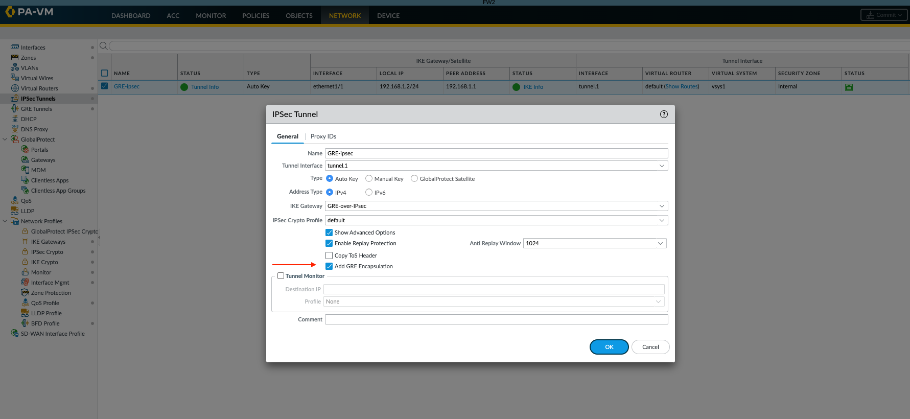
This option informs the IPSec process to expect GRE-encapsulated packets. Ensure this is configured consistently on both peers if used.
-
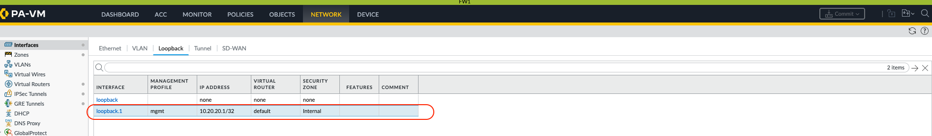
Configure Loopback Interfaces and Static Routes
Configure a loopback interface on each firewall. These loopback IPs will serve as the source and destination for the GRE packets themselves.
GUI: Network > Interfaces > Loopback > Add
-
FW-1: Loopback interface (e.g.,
loopback.1) with IP address10.20.20.1/32. Assign it to the appropriate virtual router and security zone. -
FW-2: Loopback interface (e.g.,
loopback.1) with IP address10.30.30.1/32. Assign it to the appropriate virtual router and security zone.
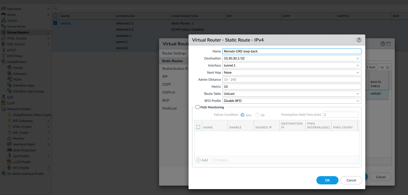
Create static routes on each firewall to ensure that the remote firewall's loopback IP address is reachable via the IPSec tunnel (
tunnel.1).GUI: Network > Virtual Routers > (select your VR) > Static Routes > Add
-
On FW-1:
-
Destination:
10.30.30.1/32(FW-2's loopback IP) -
Interface:
tunnel.1(IPSec tunnel interface) -
Next Hop: IP address of FW-2's
tunnel.1interface (e.g.,192.168.1.2) or select "None" if it's a point-to-point tunnel interface.
-
Destination:
-
On FW-2:
-
Destination:
10.20.20.1/32(FW-1's loopback IP) -
Interface:
tunnel.1(IPSec tunnel interface) -
Next Hop: IP address of FW-1's
tunnel.1interface (e.g.,192.168.1.1) or select "None".
-
Destination:
-
FW-1: Loopback interface (e.g.,
-
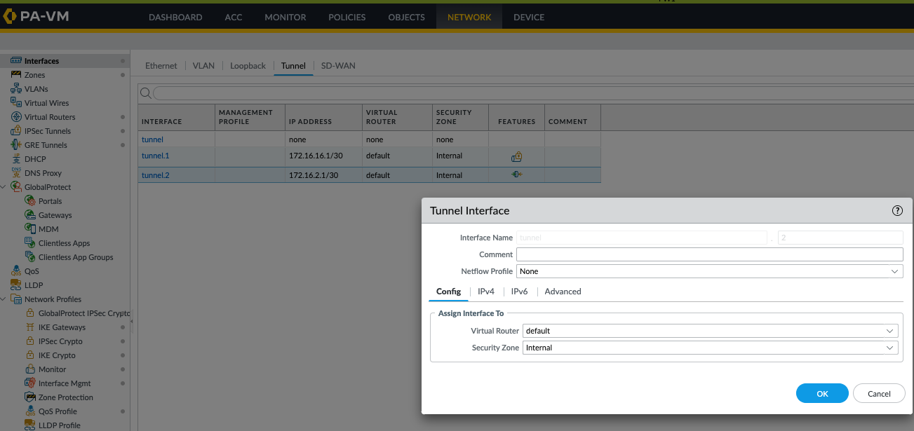
Create GRE Tunnel Interface and GRE Tunnel Object
Create a new tunnel interface for GRE (e.g.,
tunnel.2) on both firewalls. Assign an IP address to this interface (e.g., FW-1:172.16.2.1/30, FW-2:172.16.2.2/30). Assign this interface to a virtual router and a security zone.GUI: Network > Interfaces > Tunnel > Add
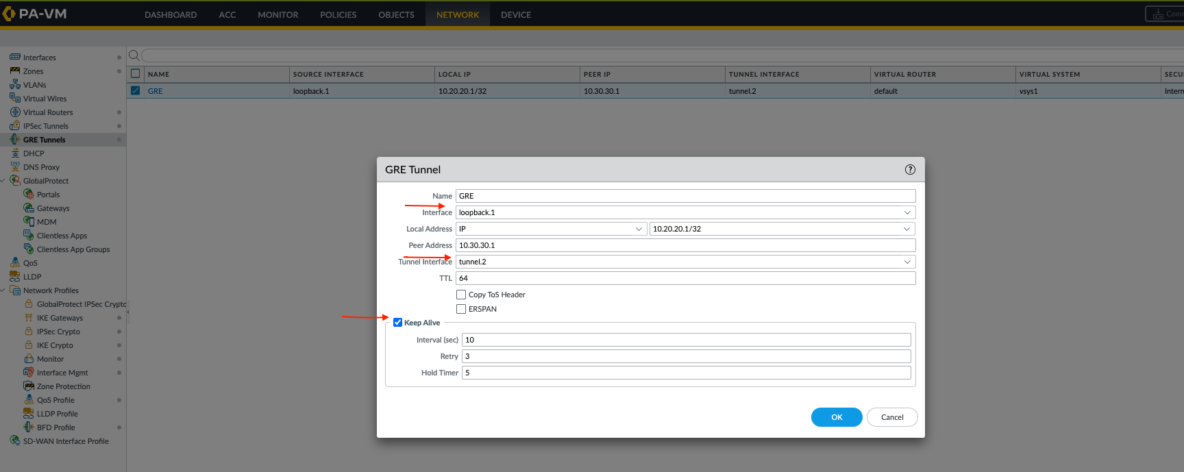
Now, create the GRE tunnel object. Use the firewalls' loopback IP addresses as the Local IP Address and Peer IP Address for the GRE tunnel configuration. Assign the newly created GRE tunnel interface (
tunnel.2) here.GUI: Network > GRE Tunnels > Add
-
On FW-1:
-
Tunnel Interface:
tunnel.2 -
Local IP Address:
10.20.20.1(FW-1's loopback) -
Peer IP Address:
10.30.30.1(FW-2's loopback) - Enable GRE Keepalive.
-
Tunnel Interface:
-
On FW-2:
-
Tunnel Interface:
tunnel.2 -
Local IP Address:
10.30.30.1(FW-2's loopback) -
Peer IP Address:
10.20.20.1(FW-1's loopback) - Enable GRE Keepalive.
-
Tunnel Interface:
Ensure GRE keepalives are enabled. This traffic will be routed over the IPSec tunnel (
tunnel.1) because of the static routes created in step 3. -
On FW-1:
-
Confirm GRE Tunnel Status
Verify that the GRE tunnel interface (
tunnel.2) is up.admin@PA-FW1> show interface tunnel.2
--------------------------------------------------------------------------------
Name: tunnel.2, ID: 258
Operation mode: layer3
Virtual router default
Interface MTU 1500
Interface IP address: 172.16.2.1/30
Interface management profile: N/A
Service configured:
Zone: Internal, virtual system: vsys1
Adjust TCP MSS: no
Ignore IPv4 DF: no
Policing: no
Proxy protocol: no
--------------------------------------------------------------------------------
GRE tunnel name: GRE
tunnel interface state: Up
disabled: False
erspan: False
copy-tos: False
keep alive enabled: True
local-ip: 10.20.20.1
peer-ip: 10.30.30.1Look for
tunnel interface state: Upand confirm the local and peer IP addresses match your loopback configurations. -
Add Routes for Traffic over GRE Tunnel
Configure static routes (or dynamic routing like OSPF/BGP) to direct traffic destined for remote internal networks via the GRE tunnel interface (
tunnel.2). For example, if FW-2 has an internal network10.100.100.0/24, on FW-1 you would add:GUI: Network > Virtual Routers > (select your VR) > Static Routes > Add
-
On FW-1:
-
Destination:
10.100.100.0/24(Remote internal network behind FW-2) -
Interface:
tunnel.2(GRE tunnel interface) -
Next Hop: IP address of FW-2's
tunnel.2interface (e.g.,172.16.2.2).
-
Destination:
Similarly, configure routes on FW-2 for networks behind FW-1 (e.g.,
10.10.10.0/24) via itstunnel.2interface, with the next hop being FW-1'stunnel.2IP (172.16.2.1).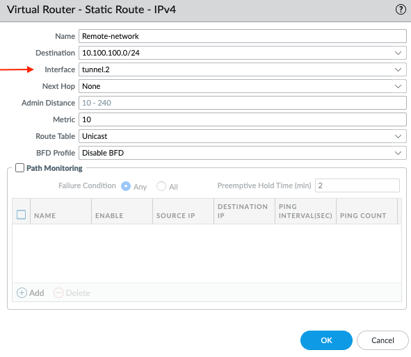
-
On FW-1:
-
Verify Connectivity
Verify connectivity by pinging from a host in one internal network to a host in the remote internal network. You can also check the session details on the firewall to confirm traffic is traversing the GRE tunnel (
tunnel.2), which itself is being transported over the IPSec tunnel (tunnel.1).admin@PA-FW1> show session all (filter for relevant traffic, e.g., ICMP)
admin@PA-FW1> show session idExample session output indicating traffic going over
tunnel.2:adminn@PA-FW1> show session id 7632 Session 7632 c2s flow: source: 10.10.10.1 [Internal] dst: 10.100.100.1 proto: 1 sport: 26067 dport: 1 state: INIT type: FLOW src user: unknown dst user: unknown s2c flow: source: 10.100.100.1 [Internal] <-- Zone might be where tunnel.2 resides dst: 10.10.10.1 proto: 1 sport: 1 dport: 26067 state: INIT type: FLOW src user: unknown dst user: unknown ..This output shows that for a session from
10.10.10.1to10.100.100.1, the egress interface istunnel.2, confirming the traffic is being routed over the GRE tunnel.Important: Ensure appropriate security policies are in place to permit:
- IPSec traffic (IKE - UDP 500, UDP 4500; ESP - protocol 50) between the public IPs of the firewalls.
-
GRE traffic (IP Protocol 47) between the loopback interface IPs (
10.20.20.1and10.30.30.1). This traffic will be sourced from the zone containing the IPSec tunnel interface (tunnel.1) and destined to the zone also containingtunnel.1(as it's encapsulated within IPSec). -
The actual data traffic (e.g., ICMP, application traffic) through the GRE tunnel interface (
tunnel.2) between the appropriate internal and GRE zones.
Other Important Information
-
MTU Considerations:
When running GRE over IPSec, the MTU needs careful consideration. Both protocols add overhead. The GRE overhead (outer IP header + GRE header) is typically around 24 bytes. IPSec (ESP in tunnel mode) adds more (e.g., 50-70+ bytes). The MTU on the GRE tunnel interface (
tunnel.2) should be lowered accordingly (e.g., to 1400 or less) to prevent fragmentation. TCP MSS clamping should also be enabled on the GRE tunnel interface. - Routing Protocol Adjacencies: Using loopback interfaces as GRE endpoints is highly recommended when running dynamic routing protocols (like OSPF or BGP) over the GRE tunnel. This ensures routing adjacencies remain stable even if a physical interface used by the underlying IPSec tunnel flaps, as long as the IPSec tunnel can re-establish over an alternate path.
-
Troubleshooting:
-
Always verify the IPSec tunnel (
tunnel.1) is up and passing traffic first. -
Check routing for loopback interfaces (ensure they are routed via
tunnel.1). -
Check routing for internal networks (ensure they are routed via
tunnel.2). -
Use packet captures on
tunnel.1to see if GRE (protocol 47) packets between loopback IPs are being exchanged and encrypted/decrypted. -
Use packet captures on
tunnel.2to see the decapsulated internal traffic.
-
Always verify the IPSec tunnel (