Panorama Overview
The Panorama™ management server provides centralized monitoring and management of multiple Palo Alto Networks next-generation firewalls and of WildFire appliances and appliance clusters. It provides a single location from which you can oversee all applications, users, and content traversing your network, and then use this knowledge to create application enablement policies that protect and control the network. Using Panorama for centralized policy and firewall management increases operational efficiency in managing and maintaining a distributed network of firewalls. Using Panorama for centralized WildFire appliance and WildFire appliance cluster management increases the number of firewalls a single network supports, provides high availability for fault tolerance, and increases management efficiency.
-
About Panorama
-
Panorama Models
-
Centralized Firewall Configuration and Update Management
-
Centralized Logging and Reporting
-
Data Redistribution Using Panorama
-
Role-Based Access Control
-
Panorama Commit, Validation, and Preview Operations
-
Plan Your Panorama Deployment
-
Deploy Panorama: Task Overview
About Panorama
Panorama enables you to effectively configure, manage, and monitor your Palo Alto Networks firewalls with central oversight. The three main areas in which Panorama adds value are:
-
Centralized configuration and deployment —To simplify central management and rapid deployment of the firewalls and WildFire appliances on your network, use Panorama to pre-stage the firewalls and WildFire appliances for deployment. You can then assemble the firewalls into groups, and create templates to apply a base network and device configuration and use device groups to administer globally shared and local policy rules. See Centralized Firewall Configuration and Update Management.
-
Aggregated logging with central oversight for analysis and reporting —Collect information on activity across all the managed firewalls on the network and centrally analyze, investigate and report on the data. This comprehensive view of network traffic, user activity, and the associated risks empowers you to respond to potential threats using the rich set of policies to securely enable applications on your network. See Centralized Logging and Reporting.
-
Distributed administration —Enables you to delegate or restrict access to global and local firewall configurations and policies. See Role-Based Access Control for delegating appropriate levels of access for distributed administration.
Six Panorama Models are available: the Panorama virtual appliance, M-600 appliance, M-500 appliance, and M-200 appliance are supported in PAN-OS 10.0 and later releases. The M-300 appliance and M-700 appliance are supported in PAN-OS 10.2 and later releases.Panorama Centralized Management illustrates how you can deploy Panorama in a high availability (HA) configuration to manage firewalls.
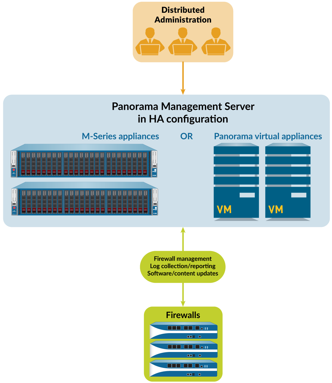
Figure 1: Panorama Centralized Management
Panorama Models
Panorama is available as one of the following virtual or physical appliances, each of which supports licenses for managing up to 25, 100, or 1,000 firewalls. Additionally, M-600 and M-700 appliances support licenses for managing up to 5,000 firewalls and similarly resourced Panorama virtual appliances support licenses for managing up to 2,500 firewalls:
-
Panorama virtual appliance —This model provides simple installation and facilitates server consolidation for sites that need a virtual management appliance. You can install Panorama on Alibaba Cloud, Amazon Web Services (AWS), AWS GovCloud, Microsoft Azure, Google Cloud Platform (GCP), KVM, Hyper-V, Oracle Cloud Infrastructure (OCI), a VMware ESXi server, or on VMware vCloud Air. The virtual appliance can collect firewall logs locally at rates of up to 20,000 logs per second and can manage Dedicated Log Collectors for higher logging rates. The virtual appliance can function as a dedicated management server, a Panorama management server with local log collection capabilities, or as a Dedicated Log Collector. For the supported interfaces, log storage capacity, and maximum log collection rates, see the Setup Prerequisites for the Panorama Virtual Appliance. You can deploy the virtual appliance in the following modes:
-
Panorama mode —In this mode, the Panorama virtual appliance supports a local Log
Collector with 1 to 12 virtual logging disks (see Deploy Panorama Virtual Appliances with
Local Log Collectors). Each logging disk has 2TB of storage capacity for a total maximum of 24TB on a single virtual appliance and 48TB on a high availability (HA) pair. Only Panorama mode enables you to add multiple virtual logging disks without losing logs on existing disks. Panorama mode also provides the benefit of faster report generation. In Panorama mode, the virtual appliance does not support NFS storage.
-
Legacy mode (ESXi and vCloud Air only)—In this mode, the Panorama virtual appliance receives and stores firewall logs without using a local Log Collector (see Deploy Panorama Virtual Appliances in Legacy Mode with Local Log Collection). By default, the virtual appliance in Legacy mode has one disk partition for all data. Approximately 11GB of the partition is allocated to log storage. If you need more local log storage, you can add one virtual disk of up to 8TB on ESXi 5.5 and later versions or on vCloud Air. Earlier ESXi versions support one virtual disk of up to 2TB. If you need more than 8TB, you can mount the virtual appliance in Legacy mode to an NFS datastore but only on the ESXi server, not in vCloud Air. This mode is only available if your Panorama virtual appliance is in Legacy mode on upgrade to PAN-OS 10.0. On upgrade to PAN-OS 9.0 and later releases, Legacy mode is no longer available if you change to any other mode. If you change your Panorama virtual appliance from Legacy mode to one of the available modes, you will no longer be able to change back into Legacy mode.
As a best practice, deploy the Panorama virtual appliance in Panorama mode to optimize log storage and report generation.
While supported, Legacy mode is not recommended for production environments but may still be used for lab or demo environments.
-
Management Only mode —In this mode, the Panorama virtual appliance is a dedicated management appliance for your managed devices and Dedicated Log Collectors.
Additionally, an appropriately resourced Panorama virtual appliance can manage up to 2,500 firewalls in this mode. The Panorama virtual appliance has no log collection capabilities except for config and system logs and requires a Dedicated Log Collector to these store logs. By default, the virtual appliance in Management Only mode has only one disk partition for all data so all logs forwarded to a Panorama virtual appliance in Management Only mode are dropped. Therefore, to store the log data from your managed appliances, you must configure log forwarding in order to store the log data from your managed devices. For more information, see Increased Device Management Capacity Requirements.
-
Log Collector mode —The Panorama virtual appliance functions as a Dedicated Log Collector. If multiple firewalls forward large volumes of log data, a Panorama virtual appliance in Log Collector mode provides increased scale and performance. In this mode, the appliance does not have a web interface for administrative access; it has only a command line interface (CLI). However, you can manage the appliance using the web interface of the Panorama management server. CLI access to a Panorama virtual appliance in Log Collector mode is necessary only for initial setup and debugging. For configuration details, see Deploy Panorama with Dedicated Log Collectors.
-
M-Series appliance —The M-200, M-300, M-500, M-600, and M-700 appliances are dedicated hardware appliances intended for large-scale deployments. In environments with high logging rates (over 10,000 logs per second) and log retention requirements, these appliances enable scaling of your log collection infrastructure. For the supported interfaces, log storage capacity, and maximum log collection rates, see M-Series Appliance Interfaces. All M-Series models share the following attributes:
-
RAID drives to store firewall logs and RAID 1 mirroring to protect against disk failures
-
SSD to store the logs that Panorama and Log Collectors generate
-
MGT, Eth1, Eth2, and Eth3 interfaces that support 1Gbps throughput
-
Redundant, hot-swappable power supplies
-
front-to-back airflow
The M-500 and M-600 appliances have the following additional attributes, which make them more suitable for data centers:
-
Eth4 and Eth5 interfaces that support 10Gbps throughput
Additionally, the following attribute makes the M-600 and M-700 appliances more suitable for large-scale firewall deployments:
-
The M-600 and M-700 appliances in Management Only mode can manage up to 5,000 firewalls.
You can deploy the M-Series appliances in the following modes:
-
Panorama mode —The appliance functions as a Panorama management server to manage firewalls and Dedicated Log Collectors. The appliance also supports a local Log Collector to aggregate firewall logs. Panorama mode is the default mode. For configuration details, see Deploy Panorama M-Series Appliances with Local Log Collectors.
-
Management Only mode —The Panorama appliance is a dedicated management appliance for your managed devices and Dedicated Log Collectors. The Panorama appliance has no log collection capabilities except for config and system logs and your deployment requires a Dedicated Log Collector to store these logs. By default, the Panorama appliance in Management Only mode has only one disk partition for all data so all logs forwarded to a
Panorama virtual appliance in Management Only mode are dropped. Therefore, to store the
log data from your managed appliances, you must configure log forwarding in order to store the log data from your managed devices.
-
Log Collector mode —The appliance functions as a Dedicated Log Collector. If multiple firewalls forward large volumes of log data, an M-Series appliance in Log Collector mode provides increased scale and performance. In this mode, the appliance does not have a web interface for administrative access; it has only a command line interface (CLI). However, you can manage the appliance using the web interface of the Panorama management server. CLI access to an M-Series appliance in Log Collector mode is necessary only for initial setup and debugging. For configuration details, see Deploy Panorama with Dedicated Log Collectors.
For more details and specifications for the M-Series appliances, see the M-Series Appliance Hardware Reference Guides .
Centralized Firewall Configuration and Update Management
Panorama ™ uses device groups and templates to group firewalls into logical sets that require similar configuration. You use device groups and templates to centrally manage all configuration elements, policies, and objects on the managed firewalls. Panorama also enables you to centrally manage licenses, software (PAN-OS® software, SSL-VPN client software, GlobalProtect™ agent/ app software), and content updates (Applications, Threats, WildFire®, and Antivirus). All device group, template, and template stack configuration objects are required to have a unique name.
In the event an unforeseen restart of your managed firewall or Panorama occurs, all uncommitted configuration changes in your device groups and templates are preserved locally until you successfully commit the changes. A restart can be the restart of the firewall or Panorama or of a PAN-OS management process related to configuration management. For firewalls or Panorama in a high availability (HA) configuration, the uncommitted configuration changes do not automatically sync across the HA peers in the event of an unforeseen restart.
-
Context Switch—Firewall or Panorama
-
Total Configuration Size for Panorama
-
Templates and Template Stacks
-
Device Groups
Context Switch—Firewall or Panorama
The Panorama™ web interface enables you to toggle between a Panorama-centric view and a firewall-centric view using the Context drop-down at the top-left of every tab. Set the Context to Panorama to manage firewalls centrally or switch context to the web interface of a specific firewall to configure it locally. The similarity of the Panorama and firewall web interfaces enables you to seamlessly move between them to monitor and manage firewalls.
The Context drop-down lists only the firewalls that are connected to Panorama. For a Device Group and Template administrator, the drop-down lists only the connected firewalls that are within the Access Domains assigned to that administrator. To search a long list, use the Filters within the drop-down.
For firewalls in a high availability (HA) configuration, the icons have colored backgrounds to indicate the HA state (as follows). Knowing the HA state is useful when selecting a firewall context. For example, you generally make firewall-specific configuration changes on an active firewall.
-
Green —Active.
-
Yellow —Passive or the firewall is initiating (the initiating state lasts for up to 60 seconds after boot up).
-
Red —The firewall is non-functional (error state), suspended (an administrator disabled the firewall), or tentative (for a link or path monitoring event in an active/active HA configuration).
When you configure an admin role profile for a Device Group and Template admin, you must assign a Device Admin Role that is pushed to your managed firewalls to context switch between the Panorama and firewall web interface.
During the context switch, Panorama validates if the admin has access to a specific vsys or for all vsys. If the admin has access to all vsys, then Panorama uses the device admin role context switch. If the admin has access to one or some of the vsys, then Panorama uses the vsys admin role to context switch.
Total Configuration Size for Panorama
The total configuration file size of Panorama™ M-Series and virtual appliances is an important piece of the performance metric when determining which M-Series appliance or the minimum amount of virtual resources you need to allocate on your Panorama virtual appliance to ensure that you meet your Security requirements. Exceeding the supported total configuration file size of the Panorama management server results in reduced performance when performing configuration changes, commits, and pushes to managed firewalls.
The Panorama management server in Panorama mode supports a total configuration file size of 80MB for all template, device group, and Panorama-specific configurations. The maximum configuration file size supported by Panorama in Management Only mode depends on the Panorama model or resources you allocate to the Panorama virtual appliance. Refer to the table below for the recommended maximum configuration file size based on the Panorama M-Series appliance model or on the resources you allocate to the Panorama virtual appliance.
| Panorama Model |
|
|
|
|---|---|---|---|
|
|
|
|
|
|
||
|
|
||
|
|
||
|
|
||
|
|
|
|
|
|
Templates and Template Stacks
You use templates and template stacks to configure the settings that enable firewalls to operate on the network. Templates are the basic building blocks you use to configure the Network and Device tabs on Panorama ™ . You can use templates to define interface and zone configurations, to manage the server profiles for logging and syslog access, or to define VPN configurations. Template stacks give you the ability to layer multiple templates and create a combined configuration. Template stacks simplify management because they allow you to define a common base configuration for all devices attached to the template stack and they give you the ability to layer templates to create a combined configuration. This enables you to define templates with location- or function-specific settings and then stack the templates in descending order of priority so that firewalls inherit the settings based on the order of the templates in the stack.
Both templates and template stacks support variables. Variables allow you to create placeholder objects with their value specified in the template or template stack based on your configuration needs. Create a template or template stack variable to replace IP addresses, Group IDs, and interfaces in your configurations. Template variables are inherited by the template stack and you can override them to create a template stack variable. However, templates do not inherit variables defined in the template stack. When a variable is defined in the template or template stack and pushed to the firewall, the value defined for the variable is displayed on the firewall.
Use templates to accommodate firewalls that have unique settings. Alternatively, you can push a broader, common base configuration and then override certain pushed settings with firewallspecific values on individual firewalls. When you override a setting on the firewall, the firewall saves that setting to its local configuration and Panorama no longer manages the setting. To restore template values after you override them, use Panorama to force the template or template stack configuration onto the firewall. For example, after you define a common NTP server in a template and override the NTP server configuration on a firewall to accommodate a local time zone, you can later revert to the NTP server defined in the template.
When defining a template stack, consider assigning firewalls that are the same hardware model and require access to similar network resources, such as gateways and syslog servers. This enables you to avoid the redundancy of adding every setting to every template stack. The following figure illustrates an example configuration in which you assign data center firewalls in the Asia-Pacific (APAC) region to a stack with global settings, one template with APAC-specific settings, and one template with data center-specific settings. To manage firewalls in an APAC branch office, you can then re-use the global and APAC-specific templates by adding them to another stack that includes a template with branch-specific settings. Templates in a stack have a configurable priority order that ensures Panorama pushes only one value for any duplicate setting. Panorama evaluates the templates listed in a stack configuration from top to bottom with higher templates having priority. The following figure illustrates a data center stack in which the data center template has a higher priority than the global template: Panorama pushes the idle timeout value from the data center template and ignores the value from the global template.
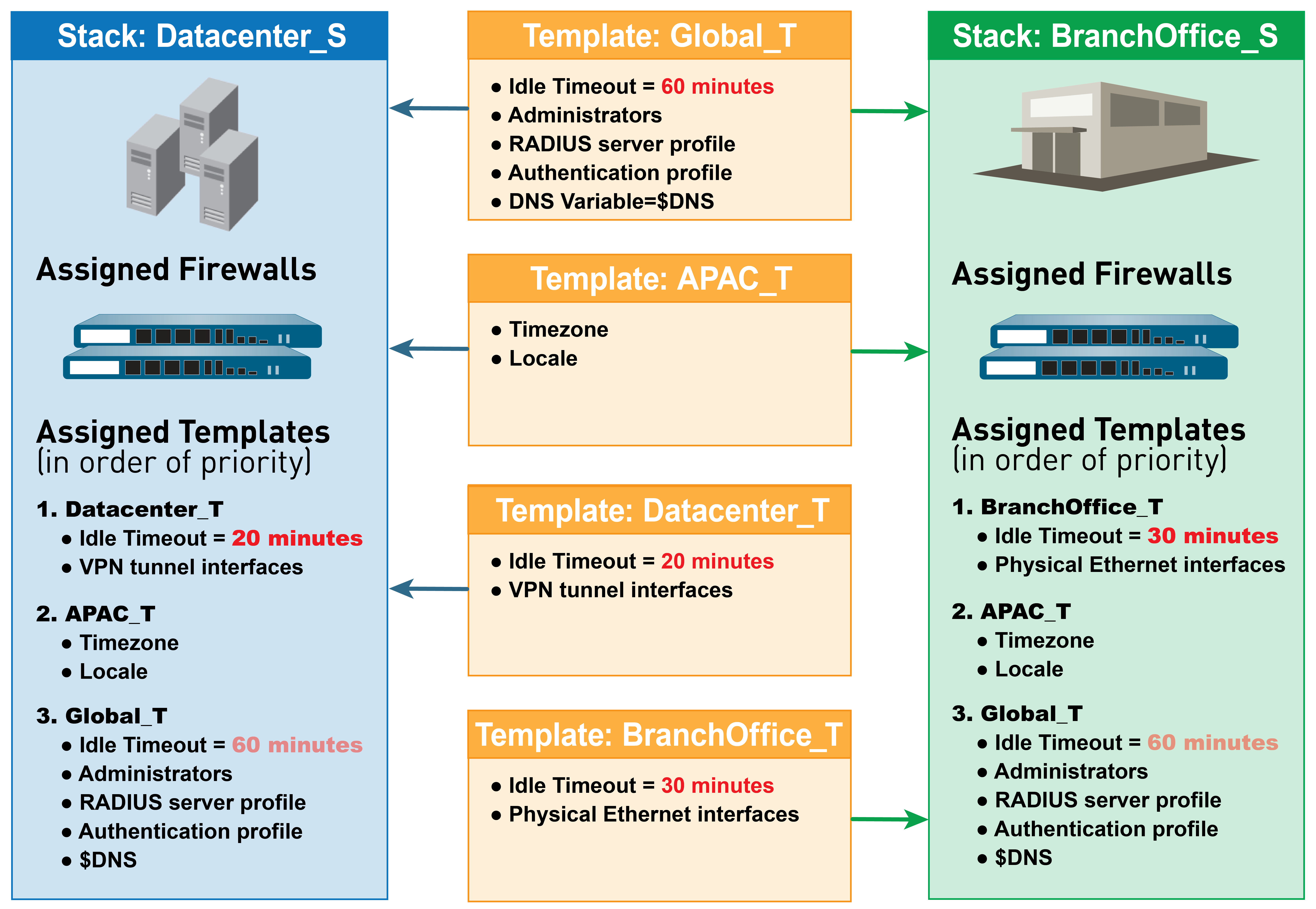
Figure 2: Template Stacks
You cannot use templates or template stacks to set firewall modes: virtual private network (VPN) mode, multiple virtual systems (multi-vsys) mode, or operational modes (normal or FIPS-CC mode). For details, see Template Capabilities and Exceptions. However, you can assign firewalls that have non-matching modes to the same template or stack. In such cases, Panorama pushes modespecific settings only to firewalls that support those modes. As an exception, you can configure Panorama to push the settings of the default vsys in a template to firewalls that don’t support virtual systems or that don’t have any virtual systems configured.
For the relevant procedures, see Manage Templates and Template Stacks.
Device Groups
To use Panorama effectively, you have to group the firewalls in your network into logical units called device groups . A device group enables grouping based on network segmentation, geographic location, organizational function, or any other common aspect of firewalls that require similar policy configurations. Using device groups, you can configure policy rules and the objects they reference. You can organize device group hierarchically, with shared rules and objects at the top, and device group-specific rules and objects at subsequent levels. This enables you to create a hierarchy of rules that enforce how firewalls handle traffic. For example, you can define a set of shared rules as a corporate acceptable use policy. Then, to allow only regional offices to access peer-to-peer traffic such as BitTorrent, you can define a device group rule that Panorama pushes only to the regional offices (or define a shared security rule and target it to the regional offices). For the relevant procedures, see Manage Device Groups. The following topics describe device group concepts and components in more detail:
-
Device Group Hierarchy
-
Device Group Policies
-
Device Group Objects
Device Group Hierarchy
You can Create a Device Group Hierarchy to nest device groups in a tree hierarchy of up to four levels, with lower-level groups inheriting the settings (policy rules and objects) of higher-level groups. At the bottom level, a device group can have parent, grandparent, and great-grandparent device groups ( ancestors ). At the top level, a device group can have child, grandchild, and greatgrandchild device groups ( descendants ). All device groups inheriting settings from the Shared location—a container at the top of the hierarchy for configurations that are common to all device groups.
Creating a device group hierarchy enables you to organize firewalls based on common policy requirements without redundant configuration. For example, you could configure shared settings that are global to all firewalls, configure device groups with function-specific settings at the first level, and configure device groups with location-specific settings at lower levels. Without a hierarchy, you would have to configure both function- and location-specific settings for every device group in a single level under Shared.
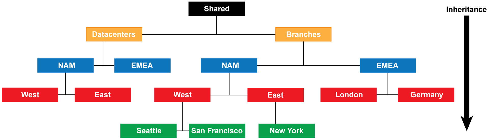
Figure 3: Device Group Hierarchy
For details on the order in which firewalls evaluate policy rules in a device group hierarchy, see Device Group Policies. For details on overriding the values of objects that device groups inherit from ancestor device groups, see Device Group Objects.
In a multiple Panorama plugin deployment to perform, a device group containing firewalls deployed in a particular hypervisor cannot be the child or parent of a device group containing firewalls deployed in a different hypervisor. For example, if Panorama receives IP address updates from VMware NSX-V and AWS, you cannot create a device group of NSX-V VM-Series firewalls that is a child of an AWS VM-Series firewall device group.

Device Group Policies
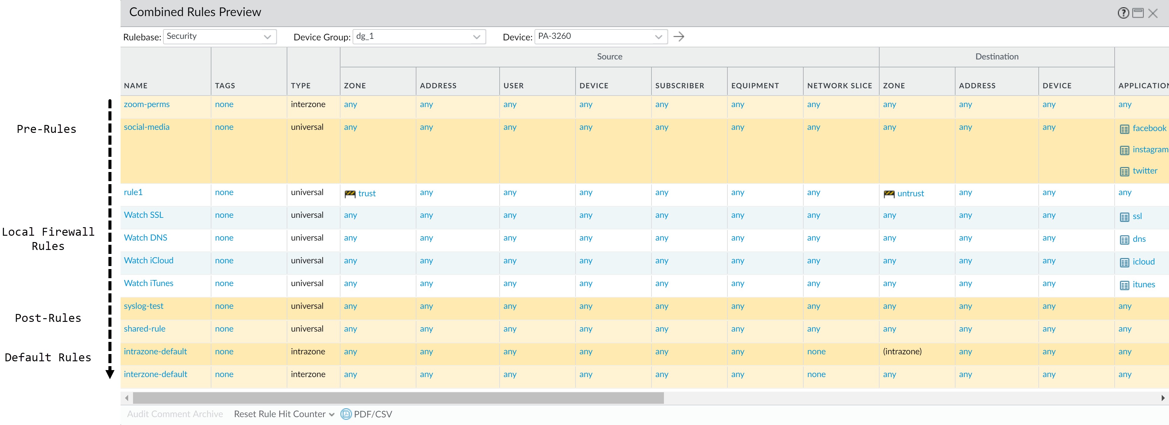
Device groups provide a way to implement a layered approach for managing policies across a network of managed firewalls. A firewall evaluates policy rules by layer (shared, device group, and local) and by type (pre-rules, post-rules, and default rules) in the following order from top to bottom. When the firewall receives traffic, it performs the action defined in the first evaluated rule that matches the traffic and disregards all subsequent rules. To change the evaluation order for rules within a particular layer, type, and rulebase (for example, shared Security pre-rules), see Manage the Rule Hierarchy.
Whether you view rules on a firewall or in Panorama, the web interface displays them in evaluation order. All the shared, device group, and default rules that the firewall inherits from
Panorama are shaded orange. Local firewall rules display between the pre-rules and post-rules.
| Evaluation Order |
|
|
|---|---|---|
|
|
|
|
||
|
|
|
|
|
|
|
||
| Evaluation Order |
|
|
|
||
|
|
|
Device Group Objects
Objects are configuration elements that policy rules reference, for example: IP addresses, URL categories, security profiles, users, services, and applications. Rules of any type (pre-rules, postrules, default rules, and rules locally defined on a firewall) and any rulebase (Security, NAT, QoS, Policy Based Forwarding, Decryption, Application Override, Captive Portal, and DoS Protection) can reference objects. You can reuse an object in any number of rules that have the same scope as that object in the Device Group Hierarchy. For example, if you add an object to the Shared location, all rules in the hierarchy can reference that shared object because all device groups inherit objects from Shared. If you add an object to a particular device group, only the rules in that device group and its descendant device groups can reference that device group object . If object values in a device group must differ from those inherited from an ancestor device group, you can Override inherited object values (see Step Override inherited object values.). You can also Revert to Inherited Object Values at any time. When you Create Objects for Use in Shared or Device Group Policy once and use them many times, you reduce administrative overhead and ensure consistency across firewall policies.
You can configure how Panorama handles objects system-wide:
-
Pushing unused objects —By default, Panorama pushes all objects to firewalls regardless of whether any shared or device group policy rules reference the objects. Optionally, you can configure Panorama to push only referenced objects. For details, see Manage Unused Shared Objects.
-
Precedence of ancestor and descendant objects —By default, when device groups at multiple levels in the hierarchy have an object with the same name but different values (because of overrides, as an example), policy rules in a descendant device group use the object values in that descendant instead of object values inherited from ancestor device groups or Shared.
Optionally, you can reverse this order of precedence to push values from Shared or the highest ancestor containing the object to all descendant device groups. For details, see Manage Precedence of Inherited Objects.
Centralized Logging and Reporting
Panorama aggregates logs from all managed firewalls and provides visibility across all the traffic on the network. It also provides an audit trail for all policy modifications and configuration changes made to the managed firewalls. In addition to aggregating logs, Panorama can forward them as SNMP traps, email notifications, syslog messages, and HTTP payloads to an external server.
For centralized logging and reporting, you also have the option to use the cloud-based Strata Logging Service that is architected to work seamlessly with Panorama. The Strata Logging Service allows your managed firewalls to forward logs to the Strata Logging Service infrastructure instead of to Panorama or to the managed Log Collectors, so you can augment your existing distributed log collection setup or to scale your current logging infrastructure without having to invest time and effort yourself.
The Application Command Center (ACC) on Panorama provides a single pane for unified reporting across all the firewalls. It enables you to centrally Monitor Network Activity, to analyze, investigate, and report on traffic and security incidents. On Panorama, you can view logs and generate reports from logs forwarded to the Strata Logging Service, Panorama or to the managed Log Collectors, if configured, or you can query the managed firewalls directly. For example, you can generate reports about traffic, threat, and/or user activity in the managed network based on logs stored on Panorama (and the managed collectors) or by accessing the logs stored locally on the managed firewalls, or in the Strata Logging Service.
If you don’t Configure Log Forwarding to Panorama or the Strata Logging Service, you can schedule reports to run on each managed firewall and forward the results to Panorama for a combined view of user activity and network traffic. Although reports don’t provide a granular drilldown on specific information and activities, they still provide a unified monitoring approach.
-
Managed Collectors and Collector Groups
-
Local and Distributed Log Collection
-
Caveats for a Collector Group with Multiple Log Collectors
-
Log Forwarding Options
-
Centralized Reporting
Managed Collectors and Collector Groups
Panorama uses Log Collectors to aggregate logs from managed firewalls. When generating reports, Panorama queries the Log Collectors for log information, providing you visibility into all the network activity that your firewalls monitor. Because you use Panorama to configure and manage Log Collectors, they are also known as managed collectors . Panorama can manage two types of Log Collectors:
-
Local Log Collector —This type of Log Collector runs locally on the Panorama management server. Only an M-700, M-600, M-500, M-300, or M-100 appliance, or Panorama virtual appliance in Panorama mode supports a local Log Collector.
-
Dedicated Log Collector —This is an M-700, M-600, M-500, M-300, M-200, or M-100 appliance or Panorama virtual appliance in Log Collector mode. You can use an M-Series appliance in Panorama mode or a Panorama virtual appliance in Panorama or Legacy (ESXi and vCloud Air) mode to manage Dedicated Log Collectors. To use the Panorama web interface for managing Dedicated Log Collectors, you must add them as managed collectors. Otherwise, administrative access to a Dedicated Log Collector is only available through its CLI using the predefined administrative user ( admin ) account. Dedicated Log Collectors don’t support additional administrative user accounts.
You can use either or both types of Log Collectors to achieve the best logging solution for your environment (see Local and Distributed Log Collection).
A Collector Group is 1 to 16 managed collectors that operate as a single logical log collection unit. If the Collector Group contains Dedicated Log Collectors, Panorama uniformly distributes the logs across all the disks in each Log Collector and across all Log Collectors in the group. This distribution optimizes the available storage space. To enable a Log Collector to receive logs, you must add it to a Collector Group. You can enable log redundancy by assigning multiple Log Collectors to a Collector Group (see Caveats for a Collector Group with Multiple Log Collectors). The Collector Group configuration specifies which managed firewalls can send logs to the Log Collectors in the group.
To configure Log Collectors and Collector Groups, see Manage Log Collection.
Local and Distributed Log Collection
Before you Configure Log Forwarding to Panorama, you must decide whether to use local Log Collectors, Dedicated Log Collectors, or both.
A local Log Collector is easy to deploy because it requires no additional hardware or virtual machine instance. In a high availability (HA) configuration, you can send logs to the local Log Collector on both Panorama peers; the passive Panorama doesn’t wait for failover to start collecting logs.
Legacy mode, which stores the logs without using a Log Collector as a logical container.
Dedicated Log Collectors are M-700, M-600, M-500, M-300, M-200, or Panorama virtual appliance in Log Collector mode. Because they perform only log collection, not firewall management, Dedicated Log Collectors allow for a more robust environment than local Log Collectors. Dedicated Log Collectors provide the following benefits:
-
Enable the Panorama management server to use more resources for management functions instead of logging.
-
Provide high-volume log storage on a dedicated hardware appliance.
-
Enable higher logging rates.
-
Provide horizontal scalability and redundancy with RAID 1 storage.
-
Optimize bandwidth resources in networks where more bandwidth is available for firewalls to send logs to nearby Log Collectors than to a remote Panorama management server.
-
Enable you to meet regional regulatory requirements (for example, regulations might not allow logs to leave a particular region).
Distributed Log Collection illustrates a topology in which the Panorama peers in an HA configuration manage the deployment and configuration of firewalls and Dedicated Log Collectors.
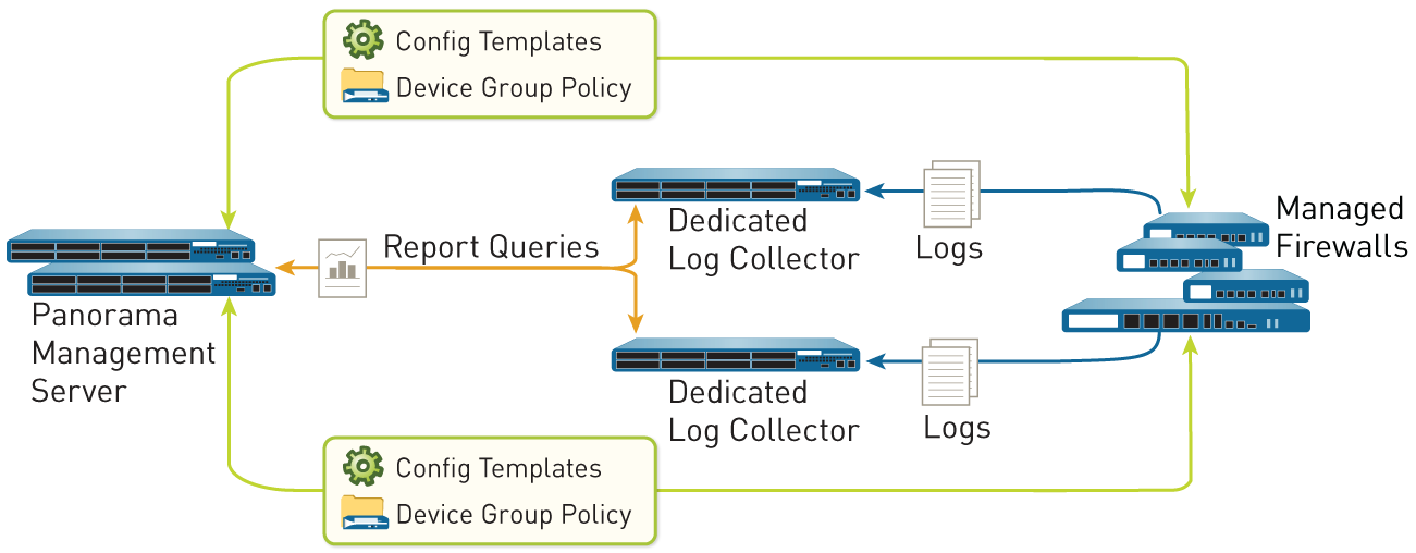
Figure 4: Distributed Log Collection
Caveats for a Collector Group with Multiple Log Collectors
You can Configure a Collector Group with multiple Log Collectors (up to 16) to ensure log redundancy, increase the log retention period, and accommodate logging rates that exceed the capacity of a single Log Collector (see Panorama Models for capacity information). In any single Collector Group, all the Log Collectors must run on the same Panorama model: all M-700 appliances, all M-600 appliances, all M-500 appliances, all M-300 appliances, all M-200 appliances, or all Panorama virtual appliances. For example, if a single managed firewall generates 48 TB of logs, the Collector Group that receives those logs will require at least three Log Collectors that are M-300 appliances or one Log Collector that is an M-700 appliance or similarly resourced Panorama virtual appliance.
A Collector Group with multiple Log Collectors uses the available storage space as one logical unit and uniformly distributes the logs across all its Log Collectors. The log distribution is based on the disk capacity of the Log Collectors (see Panorama Models) and a hash algorithm that dynamically decides which Log Collector owns the logs and writes to disk. Although Panorama uses a preference list to prioritize the list of Log Collectors to which a managed firewall can forward logs, Panorama does not necessarily write the logs to the first Log Collector specified in the preference list. For example, consider the following preference list:
| Managed Firewall |
|
|---|---|
|
|
| Managed Firewall |
|
|
|
Using this list, FW1 will forward logs to L1 so long as that primary Log Collector is available. However, based on the hash algorithm, Panorama might choose L2 as the owner who writes the logs to its disks. If L2 becomes inaccessible or has a chassis failure, FW1 won’t know because it can still connect to L1.
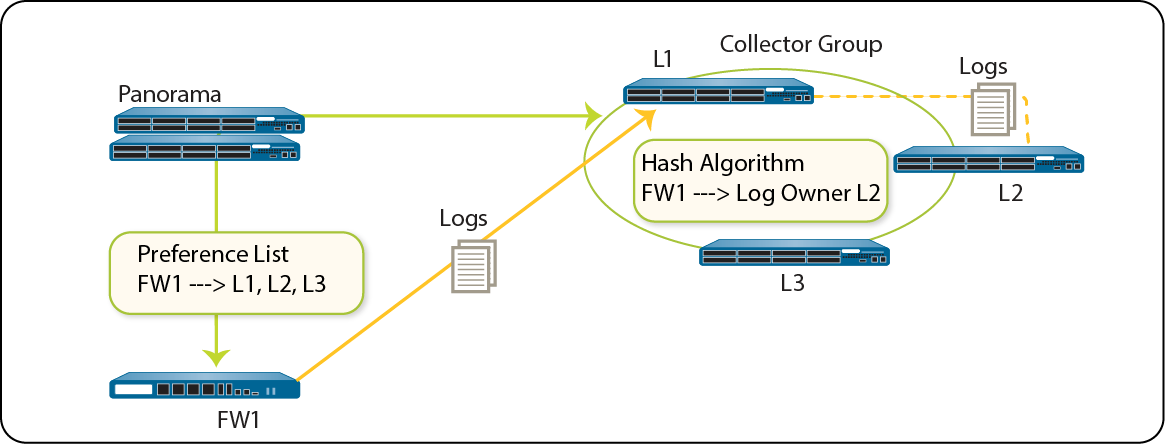
Figure 5: Example - Typical Log Collector Group Setup
In the case where a Collector Group has only one Log Collector and the Log Collector fails, the firewall stores the logs to its HDD/SSD (the available storage space varies by firewall model ). As soon as connectivity is restored to the Log Collector, the firewall resumes forwarding logs where it left off before the failure occurred.
In the case of a Collector Group with multiple Log Collectors, the firewall does not buffer logs to its local storage if only one Log Collector is down. In the example scenario where L2 is down, FW1 continues sending logs to L1, and L1 stores the log data that would be sent to L2. Once L2 is back up, L1 no longer stores log data intended for L2 and distribution resumes as expected. If one of the Log Collectors in a Collector Group goes down, the logs that would be written to the down Log Collector are redistributed to the next Log Collector in the preference list.
Two Log Collectors in a Collector Group are supported, but the Collector Group becomes non-operational if one Log Collector goes down.
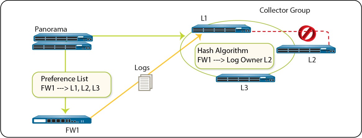
Figure 6: Example - When a Log Collector Fails
Palo Alto Networks recommends the following mitigations if using multiple Log Collectors in a Collector Group:
-
Enable log redundancy when you Configure a Collector Group. This ensures that no logs are lost if any one Log Collector in the Collector Group becomes unavailable. Each log will have two copies and each copy will reside on a different Log Collector. Log redundancy is available only if each Log Collector has the same number of logging disks.
Because enabling redundancy creates more logs, this configuration requires more storage capacity. When a Collector Group runs out of space, it deletes older logs.
Enabling redundancy doubles the log processing traffic in a Collector Group, which reduces its maximum logging rate by half, as each Log Collector must distribute a copy of each log it receives.
-
Obtain an On-Site-Spare (OSS) to enable prompt replacement if a Log Collector failure occurs.
-
In addition to forwarding logs to Panorama, configure forwarding to an external service as standby storage. The external service can be a syslog server, email server, SNMP trap server, or HTTP server.
Log Forwarding Options
By default, each firewall stores its log files locally. To use Panorama for centralized log monitoring and report generation, you must Configure Log Forwarding to Panorama. Logs are forwarded over the management interface by default unless you configure a dedicated service route to forward logs. Panorama supports forwarding logs to either a Log Collector, the Strata Logging Service , or both in parallel. You can also use external services for archiving, notification, or analysis by forwarding logs to the services directly from the firewalls or from Panorama . External services include the syslog servers, email servers, SNMP trap servers, or HTTP-based services. In addition to forwarding firewall logs, you can forward the logs that the Panorama management server and Log Collectors generate. The Panorama management server, Log Collector, or firewall that forwards the logs converts them to a format that is appropriate for the destination (syslog message, email notification, SNMP trap, or HTTP payload).
Palo Alto Networks firewalls and Panorama support the following log forwarding options. Before choosing an option, consider the logging capacities of your Panorama Models and Determine Panorama Log Storage Requirements.
• Forward logs from firewalls to Panorama and from Panorama to external services —This configuration is best for deployments in which the connections between firewalls and external services have insufficient bandwidth to sustain the logging rate, which is often the case when the connections are remote. This configuration improves firewall performance by offloading some processing to Panorama.

Figure 7: Log Forwarding to Panorama and then to External Services
• Forward logs from firewalls to Panorama and to external services in parallel —In this configuration, both Panorama and the external services are endpoints of separate log forwarding flows; the firewalls don’t rely on Panorama to forward logs to external services. This configuration is best for deployments in which the connections between firewalls and external services have sufficient bandwidth to sustain the logging rate, which is often the case when the connections are local.
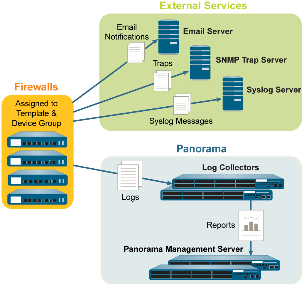
Figure 8: Log Forwarding to External Services and Panorama in Parallel
Centralized Reporting
Panorama aggregates logs from all managed firewalls and enables reporting on the aggregated data for a global view of application use, user activity, and traffic patterns across the entire network. As soon as the firewalls are added to Panorama, the ACC can display all traffic traversing your network. With logging enabled, clicking into a log entry in the ACC provides direct access to granular details about the application.
For generating reports, Panorama uses two sources: the local Panorama database and the remote firewalls that it manages. The Panorama database refers to the local storage on Panorama that is allocated for storing both summarized logs and some detailed logs. If you have a distributed Log Collection deployment, the Panorama database includes the local storage on Panorama and all the managed Log Collectors. Panorama summarizes the information—traffic, application, threat — collected from all managed firewalls at 15-minute intervals. Using the local Panorama database allows for faster response times, however, if you prefer to not forward logs to Panorama, Panorama can directly access the remote firewall and run reports on data that is stored locally on the managed firewalls.
Panorama offers more than 40 predefined reports that can be used as is, or they can be customized by combining elements of other reports to generate custom reports and report groups that can be saved. Reports can be generated on demand, on a recurring schedule, and can be scheduled for email delivery. These reports provide information on the user and the context so that you correlate events and identify patterns, trends, and potential areas of interest. With the integrated approach to logging and reporting, the ACC enables correlation of entries from multiple logs relating to the same event.
For more information, see Monitor Network Activity.
Data Redistribution Using Panorama
With data redistribution, you only have to configure each source once, then you can redistribute multiple data types to as many clients as needed. This helps you to scale your network so that you can easily add or remove source and clients as your network needs change.
Data redistribution also provides granularity by redistributing only the types of information to only the firewalls or Panorama management systems that you specify. You can use subnets, ranges, and regions to further reduce network traffic and maximize device capacity.
One of the key benefits of the Palo Alto Networks firewall is that it can enforce policies and generate reports based on usernames and tags instead of IP addresses. The challenge for largescale networks is ensuring every firewall that enforces policies and generates reports has the mappings and tags that apply for all of your policy rules. Additionally, every firewall that enforces Authentication Policy requires a complete, identical set of authentication timestamps for your user base. Whenever users authenticate to access services and applications, individual firewalls record the associated timestamps but don’t automatically share them with other firewalls to ensure consistency. Data redistribution solves these challenges for large-scale networks by enabling you to redistribute the necessary data. However, instead of setting up extra connections to redistribute the data between firewalls, you can leverage your Panorama infrastructure to Redistribute Data to Managed Firewalls. The infrastructure has existing connections that enable you to redistribute data in layers, from firewalls to Panorama. Panorama can then redistribute the information to the firewalls that enforce policies and generate reports.
Each firewall or Panorama management server can receive data from up to 100 redistribution points. The redistribution points can be other firewalls or Panorama management servers. However, you can also use Windows-based User-ID agents to perform the mapping and redistribute the information to firewalls. Only the firewalls record authentication timestamps when user traffic matches Authentication policy rules.
Role-Based Access Control
Role-based access control (RBAC) enables you to define the privileges and responsibilities of administrative users (administrators). Every administrator must have a user account that specifies a role and authentication method. Administrative Roles define access to specific configuration settings, logs, and reports within Panorama and firewall contexts. For Device Group and Template administrators, you can map roles to Access Domains, which define access to specific device groups, templates, and firewalls (through context switching). By combining each access domain with a role, you can enforce the separation of information among the functional or regional areas of your organization. For example, you can limit an administrator to monitoring activities for data center firewalls but allow that administrator to set policies for test lab firewalls. By default, every Panorama appliance (virtual appliance or M-Series appliance) has a predefined administrative account (admin) that provides full read-write access (superuser access) to all functional areas and to all device groups, templates, and firewalls. For each administrator, you can define an authentication profile that determines how Panorama verifies user access credentials.
-
Administrative Roles
-
Authentication Profiles and Sequences
-
Access Domains
-
Administrative Authentication
Administrative Roles
You configure administrator accounts based on the security requirements of your organization, any existing authentication services that your network uses, and the required administrative roles. A role defines the type of system access that is available to an administrator. You can define and restrict access as broadly or granularly as required, depending on the security requirements of your organization. For example, you might decide that a data center administrator can have access to all device and networking configurations, but a security administrator can control only security policy definitions, while other key individuals can have limited CLI or XML API access. The role types are:
-
Dynamic Roles —These are built-in roles that provide access to Panorama and managed firewalls. When new features are added, Panorama automatically updates the definitions of dynamic roles; you never need to manually update them. The following table lists the access privileges associated with dynamic roles.
| Dynamic Role |
|
|---|---|
|
|
| Dynamic Role |
|
|
|
|
|
-
Admin Role Profiles —To provide more granular access control over the functional areas of the web interface, CLI, and XML API, you can create custom roles. When new features are added to the product, you must update the roles with corresponding access privileges: Panorama does not automatically add new features to custom role definitions. You select one of the following profile types when you Configure an Admin Role Profile.
| Admin Role Profile |
|
|---|---|
|
|
|
|
| Admin Role Profile |
|
|
Authentication Profiles and Sequences
An authentication profile defines the authentication service that validates the login credentials of administrators when they access Panorama. The service can be local authentication or an external authentication service . Some services ( SAML , TACACS+ , and RADIUS) provide the option to manage both authentication and authorization for administrative accounts on the external server instead of on Panorama. In addition to the authentication service, the authentication profile defines options such as Kerberos single sign-on (SSO) and SAML single logout (SSO).
Some networks have multiple databases (such as TACACS+ and LDAP) for different users and user groups. To authenticate administrators in such cases, configure an authentication sequence — a ranked order of authentication profiles that Panorama matches an administrator against during login. Panorama checks against each profile in sequence until one successfully authenticates the administrator. An administrator is denied access only if authentication fails for all the profiles in the sequence.
Access Domains
Access domains control administrative access to specific Device Groups and templates, and also control the ability to switch context to the web interface of managed firewalls. Access domains apply only to administrators with Device Group and Template roles. Mapping Administrative Roles to access domains enables very granular control over the information that administrators access on Panorama. For example, consider a scenario where you configure an access domain that includes all the device groups for firewalls in your data centers and you assign that access domain to an administrator who is allowed to monitor data center traffic but who is not allowed to configure the firewalls. In this case, you would map the access domain to a role that enables all monitoring privileges but disables access to device group settings. Additionally, Device Group and Template admins can perform administrative tasks for managed firewalls in their access domain such as viewing the configuration and system logs, perform configuration audits, review pending tasks, and directly access firewall operations such as reboot, generating a tech support file, executing a stats dump, and exporting a core file.
You configure access domains in the local Panorama configuration and then assign them to administrative accounts and roles. You can perform the assignment locally or use an external SAML, TACACS+ , or RADIUS server. Using an external server enables you to quickly reassign access domains through your directory service instead of reconfiguring settings on Panorama. To use an external server, you must define a server profile that enables Panorama to access the server. You must also define Vendor-Specific Attributes (VSAs) on the RADIUS or TACACS+ server, or SAML attributes on the SAML IdP server.
For example, if you use a RADIUS server, you would define a VSA number and value for each administrator. The value defined has to match the access domain configured on Panorama. When an administrator tries to log in to Panorama, Panorama queries the RADIUS server for the administrator access domain and attribute number. Based on the response from the RADIUS server, the administrator is authorized for access and is restricted to the firewalls, virtual systems, device groups, and templates that are assigned to the access domain.
For the relevant procedures, see:
-
Configure an Access Domain.
-
Configure RADIUS Authentication for Panorama Administrators.
-
Configure TACACS+ Authentication for Panorama Administrators.
-
Configure SAML Authentication for Panorama Administrators.
Administrative Authentication
You can configure the following types of authentication and authorization (Administrative Roles and Access Domains) for Panorama administrators:
|
nAuthorization Method |
|
|---|---|---|
|
|
|
|
|
|
|
|
|
|
nAuthorization Method |
|
|---|---|---|
|
||
|
|
|
|
|
|
Panorama Commit, Validation, and Preview Operations
When you are ready to activate changes that you made to the candidate configuration on Panorama or to push changes to the devices that Panorama manages (firewalls, Log Collectors, and WildFire appliances and appliance clusters), you can Preview, Validate, or Commit Configuration Changes. For example, if you add a Log Collector to the Panorama configuration, firewalls cannot send logs to that Log Collector until you commit the change to Panorama and then push the change to the Collector Group that contains the Log Collector.
You can filter changes by administrator or location and then commit, push, validate, or preview only those changes. The location can be specific device groups, templates, Collector Groups, Log Collectors, shared settings, or the Panorama management server.
When you commit changes, they become part of the running configuration. Changes that you haven’t committed are part of the candidate configuration. Panorama queues commit requests so that you can initiate a new commit while a previous commit is in progress. Panorama performs the commits in the order they are initiated but prioritizes auto-commits that are initiated by Panorama (such as FQDN refreshes). However, if the queue already has the maximum number of administrator-initiated commits (10), you must wait for Panorama to finish processing a pending commit before initiating a new one. You can Use the Panorama Task Manager (
) to cancel pending commits or to see details about commits that are pending, in progress, completed, or failed. To check which changes a commit will activate, you can run a commit preview.
When you initiate a commit, Panorama checks the validity of the changes before activating them. The validation output displays conditions that block the commit (errors) or that are important to know (warnings). For example, validation could indicate an invalid route destination that you need to fix for the commit to succeed. The validation process enables you to find and fix errors before you commit (it makes no changes to the running configuration). This is useful if you have a fixed commit window and want to be sure the commit will succeed without errors.
When you preview your configuration commit, any configuration object added between existing any other existing object is displayed as a modified configuration object rather than an added configuration object. For example, Address1 and Address2 are existing Address objects. A Panorama admin later creates Address3 and adds the Address object between Address1 and Address2. When the Panorama admin goes to preview the configuration changes, Address3 is displayed as a modified configuration object.
Automated commit recovery is enabled by default, allowing the managed firewalls to locally test the configuration pushed from Panorama to verify that the new changes do not break the connection between Panorama and the managed firewall. If the committed configuration breaks the connection between Panorama and a managed firewall then the firewall automatically fails the commit and the configuration is reverted to the previous running configuration and the Shared Policy or Template Status ( Panorama > Managed Devices > Summary ) gets out of sync depending on which configuration objects were pushed. Additionally, the managed firewalls test their connection to Panorama every 60 minutes and if a managed firewall detects that it can no longer successfully connect to Panorama then it reverts its configuration to the previous running configuration.
To prevent multiple administrators from making configuration changes during concurrent sessions, see Manage Locks for Restricting Configuration Changes .
When pushing configurations to managed firewalls, Panorama pushes the running configuration. Because of this, Panorama does not let you push changes to managed firewalls until you first commit the changes to Panorama.
Plan Your Panorama Deployment
Determine the management approach. Do you plan to use Panorama to centrally configure and manage the policies, to centrally administer software, content and license updates, and/or centralize logging and reporting across the managed firewalls in the network?
If you already deployed and configured Palo Alto Networks firewalls on your network, determine whether to transition the firewalls to centralized management. This process requires a migration of all configuration and policies from your firewalls to Panorama. For details, see Transition a Firewall to Panorama Management.
-
Verify the resource allocation for your Panorama virtual appliance deployed in Log Collector mode on AWS or Azure. The Panorama virtual appliance does not retain Log Collector mode if resized. This results in log data loss.
-
Estimate the log storage capacity your network needs to meet security and compliance requirements. Consider such factors as the logging capacities of your Panorama Models, network topology, number of firewalls sending logs, type of log traffic (for example, URL Filtering and Threat logs versus Traffic logs), the rate at which firewalls generate logs, and the number of days for which you want to store logs on Panorama. For details, see Determine Panorama Log Storage Requirements.
-
Do you need to forward logs to external services (such as a syslog server) in addition to Panorama? See Log Forwarding Options.
-
Do you want to own or manage your own log storage on premises, or do you want to leverage the Strata Logging Service provided by Palo Alto Networks?
-
If you need a long-term storage solution, do you have a Security Information and Event Management (SIEM) solution, such as Splunk or ArcSight, to which you can forward logs?
-
Do you need redundancy in logging?
If you configure a Collector Group with multiple Log Collectors, you can enable redundancy to ensure that no logs are lost if any one Log Collector becomes unavailable (see Caveats for a Collector Group with Multiple Log Collectors).
If you deploy Panorama virtual appliances in Legacy mode in an HA configuration, the managed firewalls can send logs to both HA peers so that a copy of each log resides on each peer. This redundancy option is enabled by default (see Modify Log Forwarding and Buffering Defaults).
-
Will you log to a Network File System (NFS)? If the Panorama virtual appliance is in Legacy mode and does not manage Dedicated Log Collectors, NFS storage is the only option for increasing log storage capacity beyond 8TB. NFS storage is available only if Panorama runs on an ESXi server. If you use NFS storage, keep in mind that the firewalls can send logs only to the primary peer in the HA pair; only the primary peer is mounted to the NFS and can write to it.
Deploy Panorama: Task Overview
The following task list summarizes the steps to get started with Panorama. For an example of how to use Panorama for central management, see Use Case: Configure Firewalls Using Panorama.
| STEP 1 | | (M-Series appliance only) Rack mount the appliance . |
|---|---|
| STEP 2 | | Perform initial configuration to enable network access to Panorama. See Set Up the Panorama Virtual Appliance or Set Up the M-Series Appliance. |
| STEP 3 | | Register Panorama and Install Licenses. |
| STEP 4 | | Install Content and Software Updates for Panorama . |
| STEP 5 | | (Recommended) Set up Panorama in a high availability configuration. See Panorama High Availability. |
| STEP 6 | | Add a Firewall as a Managed Device. |
| STEP 7 | | Add a Device Group or Create a Device Group Hierarchy, Add a Template, and (if applicable) Configure a Template Stack. |
| STEP 8 | | (Optional) Configure log forwarding to Panorama and/or to external services. See Manage Log Collection. |
| STEP 9 | | Monitor Network Activity using the visibility and reporting tools on Panorama. |
Set Up Panorama
For centralized reporting and cohesive policy management across all the firewalls on your network, you can deploy the Panorama™ management server as a virtual appliance or as a hardware appliance (the M-200, M-300, M-500, M-600, or M-700 appliance).
The following topics describe how to set up Panorama on your network:
-
Determine Panorama Log Storage Requirements
-
Manage Large-Scale Firewall Deployments
-
Set Up the Panorama Virtual Appliance
-
Set Up the M-Series Appliance
-
Register Panorama and Install Licenses
-
Install the Panorama Device Certificate
-
Install the Device Certificate for a Dedicated Log Collector
-
Transition to a Different Panorama Model
-
Access and Navigate Panorama Management Interfaces
-
Set Up Administrative Access to Panorama
-
Set Up Authentication Using Custom Certificates
Determine Panorama Log Storage Requirements
When you Plan Your Panorama Deployment, estimate how much log storage capacity Panorama requires to determine which Panorama Models to deploy, whether to expand the storage on those appliances beyond their default capacities, whether to deploy Dedicated Log Collectors , and whether to Configure Log Forwarding from Panorama to External Destinations. When log storage reaches the maximum capacity, Panorama automatically deletes older logs to create space for new ones.
Perform the following steps to determine the approximate log storage that Panorama requires. For details and use cases, refer to Panorama Sizing and Design Guide .
STEP 1 | Determine the log retention requirements of your organization.
Factors that affect log retention requirements include:
-
IT policy of your organization
-
Log redundancy—If you enable log redundancy when you Configure a Collector Group, each log will have two copies, which doubles your required log storage capacity.
-
Regulatory requirements, such as those specified by the Payment Card Industry Data Security Standard (PCI DSS), Sarbanes-Oxley Act, and Health Insurance Portability and Accountability Act (HIPAA).
STEP 2 | Determine the average daily logging rates.
Do this multiple times each day at peak and non-peak times to estimate the average. The more often you sample the rates, the more accurate your estimate.
-
Display the current log generation rate in logs per second:
-
If Panorama is not yet collecting logs, access the CLI of each firewall, run the following command, and calculate the total rates for all the firewalls. This command displays the number of logs received in the last second.
-
> debug log-receiver statistics
-
If Panorama is already collecting logs, run the following command at the CLI of each appliance that receives logs (Panorama management server or Dedicated Log Collector) and calculate the total rates. This command gives the average logging rate for the last five minutes.
> debug log-collector log-collection-stats show incoming-logs
-
Calculate the average of the sampled rates.
-
Calculate the daily logging rate by multiplying the average logs-per-second by 86,400.
STEP 3 | Estimate the required storage capacity.
Use the formula:
[(<logs_per_second> x 86400) x <days_of retention>] x <average_log_size> ÷ (1024 x 1024 x 1024)
The average log size varies considerably by log type. However, you can use 489 bytes as an approximate average log size.
For example, if Panorama must store logs for 30 days with a log rate of 1,500 LPS, then the required log storage capacity is: [(1500 x 86400) x 30] x 489 ÷ (1024 x 1024 x 1024) = 1770GB .
The results above are calculations for the detailed logs only with the default quota settings reserve 60% of the available storage for detail logs. This means that the calculated number represents 60% of the storage used by the Log Collector. To calculate the total storage required, divide this number by .60: 1770 ÷ .6 = 2951GB .
One third, roughly 33%, of the avilable disk space is allocated to logd formatted logs to support upgrades, downgrades, and to support fixing database corruption. To calculate the total storage, divide the storage required by .66: 2951 ÷ .66 = 4471 total storage .
STEP 4 | Next steps...
If you determine that Panorama requires more log storage capacity:
-
Expand Log Storage Capacity on the Panorama Virtual Appliance.
-
Increase Storage on the M-Series Appliance.
Manage Large-Scale Firewall Deployments
Panorama™ provides multiple options to manage a large-scale firewall deployment. For consolidation of all management functions, Panorama supports management of up to 5,000 firewalls using an M-600, M-700 appliance, or Panorama virtual appliance on ESXi in Management Only mode or up to 2,500 firewalls with a Panorama virtual appliance in Management Only mode. To simplify the deployment and operational management of a large-scale firewall deployment greater than 5,000 firewalls, the Panorama Interconnect plugin allows you to manage multiple Panorama management server Nodes from a single Panorama Controller.
-
Determine the Optimal Large-Scale Firewall Deployment Solution
-
Increased Device Management Capacity for M-Series and Panorama Virtual Appliance
Determine the Optimal Large-Scale Firewall Deployment Solution
To ease the operational burden of managing the configuration of your large-scale firewall deployment, Palo Alto Networks provides different firewall management options to best suit your deployment scenario.
If your large-scale firewall deployment is composed of one or very few Panorama management servers, you can deploy an M-600, M-700 appliance, or Panorama virtual appliance on ESXi to manage up to 5,000 firewalls, or Panorama virtual appliance to manage up to 2,500 firewalls, to leverage all Panorama capabilities from a single Panorama management server. The Increased Device Management Capacity for M-Series and Panorama Virtual Appliance is ideal for vertically scaled deployments where you manage a large number of firewalls from a single Panorama management server rather than deploying multiple Panorama management servers to manage fewer firewalls.
If your large-scale firewall deployment is composed of multiple Panorama management servers with similar configurations, the Panorama Interconnect plugin allows you to manage multiple Panorama Nodes from a single Panorama Controller. This plugin simplifies the deployment and operational management of large scale firewall deployments because you can centrally manage policy and configuration from a Panorama Controller. From the Panorama Controller, the device group and template stack configuration is synchronized to the Panorama Nodes and pushed to managed devices. The Panorama Interconnect plugin is ideal for horizontally-scaled firewall deployments with multiple distributed Panorama management servers.
Increased Device Management Capacity for M-Series and Panorama Virtual Appliance
You can manage up to 5,000 firewalls using a single M-600, M-700 appliance, or Panorama™ virtual appliance installed on VMware ESXi, or up to 2,5000 firewalls with all other supported Panorama virtual appliances in order to reduce the management footprint of your large-scale firewall deployment.
-
Increased Device Management Capacity Requirements
-
Install Panorama for Increased Device Management Capacity
Increased Device Management Capacity Requirements
You can manage up to 5,000 firewalls using a single M-600, M-700 appliance, or Panorama™ virtual appliance installed on VMware ESXi, or up to 2,500 firewalls with all other supported Panorama virtual appliances. For managing such large deployments from a single Panorama management server alleviates the operational complexity of configuration management and reduces the security and compliance risk of managing multiple Panorama management servers. For details about the maximum number of template stacks that Panorama supports, see Template Stacks .
For log collection, a single Panorama management server is ideal because it provides a centralized location to view and analyze log data from managed devices rather than requiring you to access each individual Panorama management server. To provide redundancy in the event of system or network failure, Palo Alto Networks recommends deploying two Panorama management servers in a high availability (HA) configuration. For Panorama system and config logs, an additional disk with a minimum 92GB capacity is required. This additional disk is automatically detected by the Panorama virtual appliance when Panorama is rebooted and mounted as a partition for system and config log storage.
For generating pre-defined reports , you must enable Panorama to use Panorama data for predefined reports. This generates pre-defined reports using log data already collected by Panorama or the Dedicated Log Collector, which reduces the resource utilization when generating reports. Enabling this setting is required, otherwise Panorama performance may be impacted, and Panorama may become unresponsive.
To manage up to 5,000 firewalls, the Panorama management server must meet the following minimum requirements:
| Requirement |
|
|
|---|---|---|
|
|
|
|
|
|
|
|
|
|
|
|
| Requirement |
|
|
|
|
|
|
|
|
|
|
Install Panorama for Increased Device Management Capacity
Activate the device management license to manage more than 1,000 firewalls from a single M-600 Panorama™ management server or a single Panorama virtual appliance.
STEP 1 | Contact your Palo Alto Networks sales representative to obtain the Panorama device management license that enables you to manage up to 5,000 firewalls.
-
If you are deploying an M-600 appliance, obtain the PAN-M-600-P-1K device management license.
-
If you are deploying an M-700 appliance, obtain the PAN-M-700-P-1K device management license.
-
If you are deploying a Panorama virtual appliance, obtain the PAN-PRA-1000 device management license.
STEP 2 | Set up the Panorama management server.
-
(M-600 and M-700 appliances only) Set Up the M-Series Appliance.
or
-
Set Up the Panorama Virtual Appliance.
STEP 3 | Increase the System Disk for Panorama on an ESXi Server to 224GB.
A 224GB system disk is required for a Panorama virtual appliance installed on VMware ESXi to manage up to 5,000 firewalls. Review the Increased Device Management Capacity Requirements for more information.
STEP 4 | Change the Panorama management server to Management Only mode if Panorama is not already in this mode.
-
Begin at Step 5 to Set Up an M-Series Appliance in Management Only Mode.
-
Set up a Panorama Virtual Appliance in Management Only Mode.
| STEP 5 | |
Register your Panorama management server and install licenses.
|
|---|---|
| STEP 6 | | Select Panorama > Licenses and verify that the device management license is successfully |
activated.
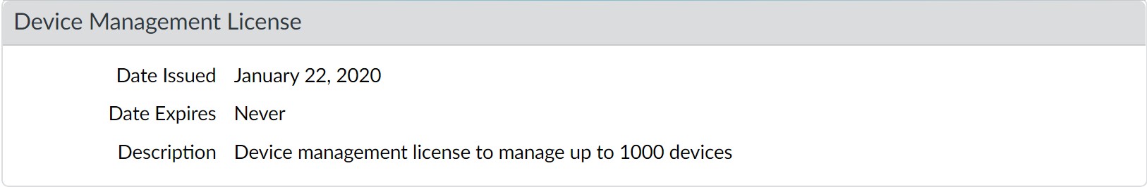
appliance on ESXi, or up to 2,500 firewalls with a Panorama virtual appliance, but the Description still displays Device management license to manage up to 1000 devices or more.
Set Up the Panorama Virtual Appliance
The Panorama virtual appliance enables you to use your existing VMware virtual infrastructure to centrally manage and monitor Palo Alto Networks firewalls and Dedicated Log Collectors. You can install the virtual appliance on an ESXi server, Alibaba Cloud, Amazon Web Services (AWS), AWS GovCloud, Microsoft Azure, Google Cloud Platform (GCP), KVM, Hyper-V, or in vCloud Air. In addition to or instead of deploying Dedicated Log Collectors, you can forward firewall logs directly to the Panorama virtual appliance. For greater log storage capacity and faster reporting, you have the option to switch the virtual appliance from Legacy mode to Panorama mode and configure a local Log Collector. For more details about the Panorama virtual appliance and its modes, see Panorama Models.
-
Setup Prerequisites for the Panorama Virtual Appliance
-
Install the Panorama Virtual Appliance
-
Perform Initial Configuration of the Panorama Virtual Appliance
-
Set Up The Panorama Virtual Appliance as a Log Collector
-
Set Up the Panorama Virtual Appliance with Local Log Collector
-
Set up a Panorama Virtual Appliance in Panorama Mode
-
Set up a Panorama Virtual Appliance in Management Only Mode
-
Expand Log Storage Capacity on the Panorama Virtual Appliance
-
Increase CPUs and Memory on the Panorama Virtual Appliance
-
Increase the System Disk on the Panorama Virtual Appliance
-
Complete the Panorama Virtual Appliance Setup
-
Convert Your Panorama Virtual Appliance
Setup Prerequisites for the Panorama Virtual Appliance
Complete the following tasks before you Install the Panorama Virtual Appliance:
Review the minimum resource requirements for deploying the Panorama virtual appliance on
Alibaba Cloud, Amazon Web Services (AWS), AWS GovCloud, Microsoft Azure, Google Cloud Platform (GCP), Hyper-V, KVM, Oracle Cloud Infrastructure (OCI), and VMware ESXi to ensure that the virtual machine meets the minimum required resources for the desired mode (Panorama, Management Only, or Log Collector). The minimum resource requirements for the Panorama virtual appliance are designed to help you achieve the maximum number of logs per second (LPS) for log collection in Panorama and Log Collector mode. If you add or remove virtual logging disks that results in a configuration that does not meet or exceed the number of virtual logging disks recommended (below), your LPS will be reduced.
If the minimum resource requirements are not met for Panorama mode when you Install the Panorama Virtual Appliance, Panorama defaults to Management Only mode for all supported public (Alibaba Cloud, AWS, AWS GovCloud, Azure, GCP, and OCI) and private (Hyper-V, KVM, and VMware ESXi) hypervisors. If the minimum resource requirements are not met for Management Only mode, Panorama defaults to Maintenance mode for all supported public hypervisors, Hyper-V, and KVM. If the minimum resource requirements for Management Only mode are not met when you Install Panorama on VMware, Panorama defaults to Legacy mode.
Table 1: System Requirements for the Panorama Virtual Appliance
|
tsPanorama Virtual
|
|
|
|---|---|---|---|
|
|
|
tsPanorama Virtual
|
|
|
|---|---|---|---|
|
|||
|
|
||
|
|
|
tsPanorama Virtual
|
|
|
|---|---|---|---|
|
|
|
|
|
|||
|
|
|
|
|
tsPanorama Virtual
|
|
|
|
|
|
|
Supported Interfaces
Interfaces can be used for device management, log collection, Collector Group communication, licensing and software updates. The Panorama virtual appliance supports up to six interfaces (MGT and Eth1 - Eth5).
Table 2: Supported interfaces for public hypervisors
|
|
|
|
|
|
|
|---|---|---|---|---|---|---|
|
|
|
|
|
|
|
|
|
|
|
|
|
|
|
interface onsupported |
|
|
|
|
|
|
|
|
|
|
|
|
Table 3: Supported Interfaces for Private Hypervisors
| Function |
|
|
|
|---|---|---|---|
|
|
|
|
| Function |
|
|
|
|
|
|
|
|
|
|
|
|
|
|
|
Install the Panorama Virtual Appliance
Before installation, decide whether to run the virtual appliance in Panorama mode, Management Only mode, Log Collector mode, or Legacy mode (VMware only). Each mode has different resource requirements, as described in Setup Prerequisites for the Panorama Virtual Appliance. You must complete the prerequisites before starting the installation.
-
Install Panorama on VMware
-
Set Up Panorama on Alibaba Cloud
-
Install Panorama on AWS
-
Install Panorama on AWS GovCloud
-
Install Panorama on Azure
-
Install Panorama on Google Cloud Platform
-
Install Panorama on KVM
-
Install Panorama on Hyper-V
-
Set Up Panorama on Oracle Cloud Infrastructure (OCI)
Install Panorama on VMware
You can install the Panorama virtual appliance on the ESXi and vCloud Air VMware platforms.
-
Install Panorama on an ESXi Server
-
Install Panorama on vCloud Air
-
Support for VMware Tools on the Panorama Virtual Appliance
Install Panorama on an ESXi Server
Use these instructions to install a new Panorama virtual appliance on a VMware ESXi server. For upgrades to an existing Panorama virtual appliance, skip to Install Content and Software Updates for Panorama .
| STEP 1 | |
Download the Panorama 11.1 base image Open Virtual Appliance (OVA) file.
|
|---|---|
| STEP 2 | | Install Panorama. |
-
Launch the VMware vSphere Client and connect to the VMware server.
-
Select File > Deploy OVF Template .
-
Browse to select the Panorama OVA file and click Next .
-
Confirm that the product name and description match the downloaded version, and click Next .
-
Enter a descriptive name for the Panorama virtual appliance, and click Next .
-
Select a datastore location (system disk) on which to install the Panorama image. See the Setup Prerequisites for the Panorama Virtual Appliance for the supported Default system disk sizes. After selecting the datastore, click Next .
-
Select Thick Provision Lazy Zeroed as the disk format, and click Next .
-
Specify which networks in the inventory to use for the Panorama virtual appliance, and click Next .
-
Confirm the selected options, click Finish to start the installation process, and click Close when it finishes. Do not power on the Panorama virtual appliance yet.
STEP 3 | Configure resources on the Panorama virtual appliance.
-
Right-click the Panorama virtual appliance and Edit Settings .
-
In the Hardware settings, allocate the CPUs and memory as necessary.
-
Set the SCSI Controller to LSI Logic Parallel .
-
(Optional) Add a virtual logging disk.
This step is required in the following scenarios:
-
In Panorama mode to store logs on a dedicated logging disk.
-
Manage your SD-WAN deployment in Management Only mode.
-
Add a disk, select Hard Disk as the hardware type, and click Next .
-
Create a new virtual disk and click Next .
-
Set the Disk Size to exactly 2TB.
-
Select your preferred Disk Provisioning disk format.
Consider your business needs when selecting the disk provisioning format. For more information regarding the disk provisioning performance considerations, refer to the VMware Thick vs Thin Disks and All Flash Arrays document, or additional VMware documentation.
-
Select Specify a datastore or datastore structure as the location, Browse to a datastore that has sufficient storage, click OK , and click Next .
-
Select a SCSI Virtual Device Node (you can use the default selection) and click Next .
Panorama will fail to boot if you select a format other than SCSI.
-
Verify that the settings are correct and click Finish .
-
Click OK to save your changes.
| STEP 4 | |
Power on the Panorama virtual appliance.
|
|---|---|
| STEP 5 | | Configure a new administrative password for the Panorama virtual appliance. |
You must configure a unique administrative password before you can access the web interface or CLI of the Panorama virtual appliance. The new password must be a minimum of eight characters and include a minimum of one lowercase character, one uppercase character, and one number or special character.
When you first log in to the Panorama CLI, you are prompted to enter the Old Password and the New Password for the admin user before you can continue.
STEP 6 | Verify the Panorama is running the correct system mode.
admin> show system info
In the output, the system-mode indicates either panorama or management-only mode.
STEP 7 | Register the Panorama virtual appliance and activate the device management license and support licenses.
-
(VM Flex Licensing Only) Provisioning the Panorama Virtual Appliance Serial Number .
When leveraging VM Flex licensing, this step is required to generate the Panorama virtual appliance serial number needed to register the Panorama virtual appliance with the Palo Alto Networks Customer Support Portal (CSP).
-
Register Panorama.
You must register the Panorama virtual appliance using the serial number provided by Palo Alto Networks in the order fulfillment email.
This step is not required when leveraging VM Flex licensing as the serial number is automatically registered with the CSP when generated.
-
Activate the firewall management license.
-
Activate/Retrieve a Firewall Management License when the Panorama Virtual Appliance is Internet-connected.
-
Activate/Retrieve a Firewall Management License when the Panorama Virtual Appliance is not Internet-connected.
-
-
Activate a Panorama Support License.
STEP 8 | Increase the System Disk for Panorama on an ESXi Server if you intend to use the Panorama virtual appliance for the following:
-
Manage your SD-WAN deployment in Panorama mode.
-
Requires additional storage space for dynamic updates when managing large-scale firewall deployments.
STEP 9 | Complete configuring the Panorama virtual appliance for your deployment needs.
-
For Panorama in Log Collector Mode.
-
Add a Virtual Disk to Panorama on an ESXi Server as needed.
-
Adding at least one virtual logging disk is required before you can change the Panorama virtual appliance to Log Collector mode.
-
Begin at Step 6 to switch to Log Collector mode.
-
For Panorama in Panorama mode.
-
Add a Virtual Disk to Panorama on an ESXi Server.
-
Adding at least one virtual logging disk is required before you can change the Panorama virtual appliance to Panorama mode.
-
Set up a Panorama Virtual Appliance in Panorama Mode.
-
Configure a Managed Collector.
-
For Panorama in Management Only mode.
-
Set up a Panorama Virtual Appliance in Management Only Mode.
-
Configure a Managed Collector to add a Dedicated Log Collector to the Panorama virtual appliance.
-
Management Only mode does not support local log collection, and requires a Dedicated Log Collector to store managed device logs.
-
For SD-WAN deployments.
-
Increase the System Disk for Panorama on an ESXi Server
-
To leverage SD-WAN on Panorama deployed on ESXi, you must increase the system disk to 224GB.
-
Set up a Panorama Virtual Appliance in Management Only Mode.
-
Add a Virtual Disk to Panorama on an ESXi Server.
To leverage SD-WAN, you must add a single 2TB logging disk to Panorama in Management Only mode.
Install Panorama on vCloud Air
Use these instructions to install a new Panorama virtual appliance in VMware vCloud Air. If you are upgrading a Panorama virtual appliance deployed in vCloud Air, skip to Install Content and Software Updates for Panorama .
STEP 1 | Download the Panorama 11.1 base image Open Virtual Appliance (OVA) file.
-
Go to the Palo Alto Networks software downloads site . (If you can’t log in, go to the Palo Alto Networks Customer Support web site for assistance.)
-
In the Download column in the Panorama Base Images section, download the Panorama
11.1 release OVA file (Panorama-ESX-10.0.0.ova).
STEP 2 | Import the Panorama image to the vCloud Air catalog.
For details on these steps, refer to the OVF Tool User’s Guide .
-
Install the OVF Tool on your client system.
-
Access the client system CLI.
-
Navigate to the OVF Tool directory (for example, C:\Program Files\VMware\VMware OVF Tool).
-
Convert the OVA file to an OVF package:
ovftool.exe <OVA‑file‑pathname> <OVF‑file‑pathname>
-
Use a browser to access the vCloud Air web console, select your Virtual Private Cloud OnDemand location, and record the browser URL. You will use the URL information to complete the next step. The URL format is:
https:// <virtual‑cloud‑location> .vchs.vmware.com/compute/ cloud/org/ <vCloud‑account‑number> /#/catalogVAppTemplateList? catalog= <catalog‑ID> .
-
Import the OVF package, using the information from the vCloud Air URL to complete the <virtual‑cloud‑location>, <vCloud‑account‑number>, and <catalog‑ID> variables. The other variables are your vCloud Air username and domain <user>@<domain>, a virtual data center <datacenter>, and a vCloud Air template <template>.
ovftool.exe -st="OVF" " <OVF‑file‑pathname> "
"vcloud:// <user> @ <domain> :password@ <virtual-cloudlocation> .vchs.vmware.com?vdc= <datacenter> &org= <vCloudaccount-number> &vappTemplate= <template> .ovf&catalog=default-
catalog"
| STEP 3 | | Install Panorama. | |
|---|---|---|
|
Access the vCloud Air web console and select your Virtual Private Cloud OnDemand region. | |
|
Create a Panorama virtual machine. For the steps, refer to Add a Virtual Machine from a Template in the vCloud Air Documentation Center. Configure the CPU , Memory and Storage as follows:
|
|
| STEP 4 | | Create vCloud Air NAT rules on the gateway to allow inbound and outbound traffic for the Panorama virtual appliance. |
Refer to Add a NAT Rule in the vCloud Air Documentation Center for the detailed instructions:
-
Add a NAT rule that allows Panorama to receive traffic from the firewalls and allows administrators to access Panorama.
-
Add a NAT rule that allows Panorama to retrieve updates from the Palo Alto Networks update server and to access the firewalls.
STEP 5 | Create a vCloud Air firewall rule to allow inbound traffic on the Panorama virtual appliance.
Outbound traffic is allowed by default.
Refer to Add a Firewall Rule in the vCloud Air Documentation Center for the detailed instructions.
STEP 6 | Power on the Panorama virtual appliance if it isn’t already on.
In the vCloud Air web console, select the Virtual Machines tab, select the Panorama virtual machine, and click Power On .
You are now ready to Perform Initial Configuration of the Panorama Virtual Appliance.
Support for VMware Tools on the Panorama Virtual Appliance
VMware Tools is bundled with the software image (ovf) for the Panorama virtual appliance. The support for VMware Tools allows you to use the vSphere environment—vCloud Director and vCenter server—for the following:
-
View the IP address assigned to the Panorama management interface.
-
View resource utilization metrics on hard disk, memory, and CPU. You can use these metrics to enable alarms or actions on the vCenter server or vCloud Director.
-
Graceful shutdown and restart of Panorama using the power off function on the vCenter server or vCloud Director.
-
Enables a heartbeat mechanism between the vCenter server and Panorama for verifying that Panorama is functioning, or if the firewall/Panorama is rebooting. If the firewall goes into maintenance mode, heartbeats are disabled so that the vCenter server does not shut down the firewall. Disabling heartbeats allows the firewall to stay operational in maintenance mode when it cannot not send heartbeats to the vCenter server.
Set Up Panorama on Alibaba Cloud
Set up a Panorama™ virtual appliance on Alibaba Cloud to centrally managed the configuration of physical and VM-Series firewalls.
• Upload the Panorama Virtual Appliance Image to Alibaba Cloud • Install Panorama on Alibaba Cloud
Upload the Panorama Virtual Appliance Image to Alibaba Cloud
Complete the following procedure to upload a Panorama™ management server qcow2 file for KVM and create a custom image that you need to launch the Panorama virtual appliance. Uploading and creating the image is required only once. You can use the same image for all subsequent deployments of the Panorama virtual appliance.
| STEP 1 | |
Download the Panorama qcow2 file for KVM from the Palo Alto Networks Customer Support Portal (CSP).
|
|---|---|
| STEP 2 | | Log in to the Alibaba Cloud Console . |
| STEP 3 | | Create an Object Storage Service (OSS) bucket for the Panorama virtual appliance image. |
-
From the Alibaba Cloud menu, select Object Storage Service > Buckets and Create Bucket .
-
Enter a descriptive Bucket Name .
-
Select the bucket Region .
This region must be in the same region you plan on deploying your Panorama virtual appliance and in the same region as the firewalls you plan to manage with Panorama.
-
Configure the remaining OSS bucket settings as needed.
-
Click OK .
You are automatically taken to the OSS bucket Overview page after successful creation.
STEP 4 | Upload the qcow2 file to the OSS bucket.
-
In the OSS bucket Overview, select Files and Upload the qcow2 file you downloaded in the previous step.
-
For Upload To target, select Current .
-
For the File ACL , select Inherited from Bucket .
-
Click Select Files and select the qcow2 file.
Alternatively, you can drag and drop the qcow2 file into the Files to Upload section.
-
Upload the qcow2 file.
A Task List window appears displaying the upload Status. Continue to the next step after the qcow2 file upload Status displays Uploaded .
STEP 5 | Make the qcow2 file a bootable image.
-
In the OSS bucket Overview, select Files and click the qcow2 file you uploaded to view the file Details.
-
Click Copy File URL and exit the file Details.
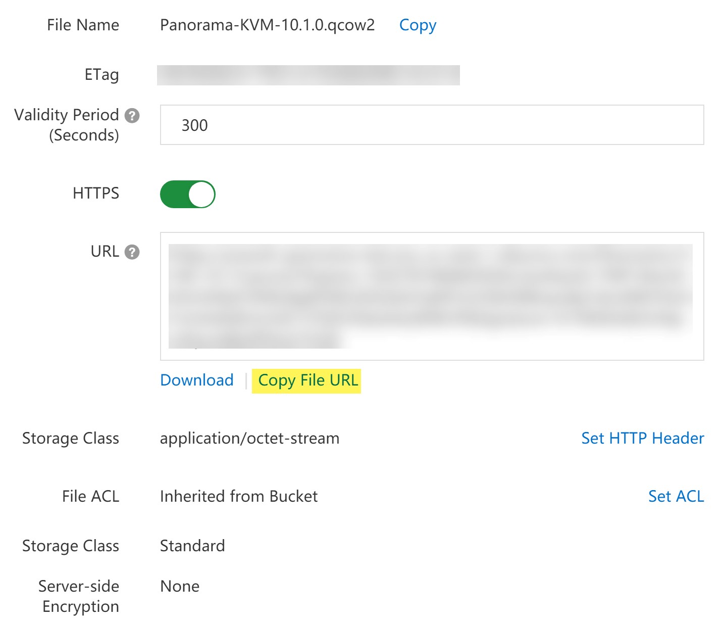
-
From the Alibaba Cloud menu, select Elastic Compute Service > Instances & Images > Images and Import Image .
-
Paste the OSS Object Address for the qcow2 file.
This the file URL you copied in the previous step.
-
Enter an Image Name .
-
For the Operating System/Platform , select Linux CentOS .
-
For the System Disk (GiB) , enter 81 .
-
For the System Architecture , select x86_64 .
-
For the Image Format , select QCOW2 .
-
Click OK .
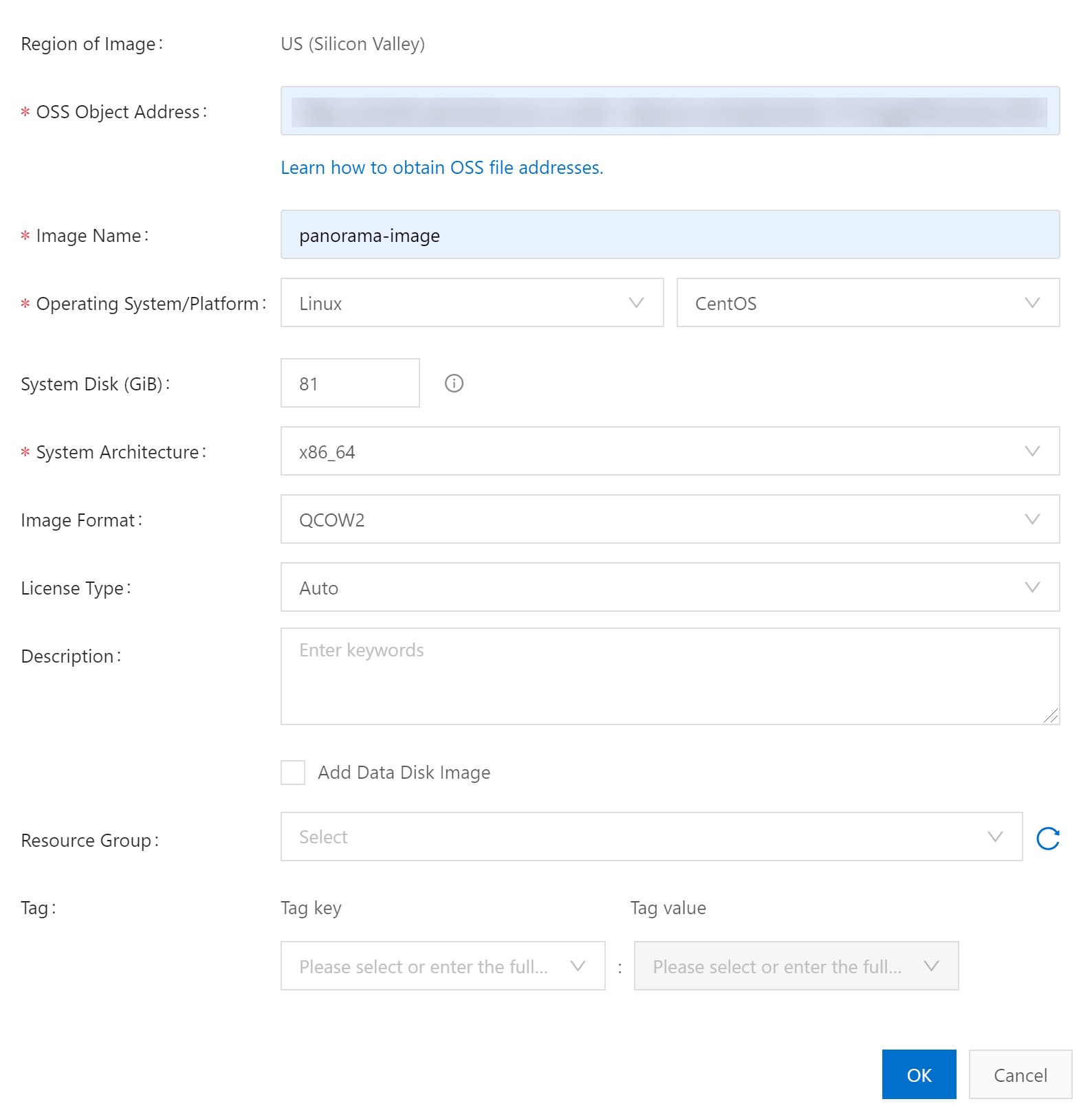
Install Panorama on Alibaba Cloud
Use the Elastic Compute Service (ECS) to create a Panorama™ virtual appliance instance on
Alibaba Cloud. An ECS instance supports a single NIC by default and automatically attached an Elastic Network Interface (ENI) to it. You must manually upload a Panorama virtual appliance qcow2 image downloaded from the Palo Alto Networks Customer Supported Portal (CSP) to Alibaba Cloud to successfully install the Panorama virtual appliance on Alibaba Cloud.
A Panorama virtual appliance deployed on Alibaba Cloud is Bring Your Own License (BYOL), supports all deployment modes (Panorama, Log Collector, and Management Only), and shares the same processes and functionality as the M-Series hardware appliances. For more information on Panorama modes, see Panorama Models.
Review the Setup Prerequisites for the Panorama Virtual Appliance to determine the correct Elastic Computer Service (ECS) instance type for your needs. The virtual resources requirement for the Panorama virtual appliance is based on the total number of firewalls managed by the Panorama virtual appliance and the required Logs Per Second (LPS) for forwarding logs from your managed firewalls to your Log Collector.
Palo Alto Networks supports the following instance types.
-
ecs.g5.xlarge, ecs.g5.2xlarge, ecs.g5.4xlarge
-
ecs.sn2ne.xlarge, ecs.sn2ne.2xlarge, ecs.sn2ne.4xlarge
STEP 1 | Log in to the Alibaba Cloud Console .
STEP 2 | Upload the Panorama Virtual Appliance Image to Alibaba Cloud.
STEP 3 | Set up the virtual private cloud (VPC) for your network needs.
Whether you launch the Panorama virtual appliance in an existing VPC or you create a new
VPC, the Panorama virtual appliance must be able to receive traffic from other instances in the VPC and perform inbound and outbound communication between the VPC and the internet as needed.
Refer to the Alibaba Cloud VPC documentation for more information.
-
Create a VPC and Configure Networks or use an existing VPC.
-
Verify that the network and security components are appropriately defined.
-
Create an internet gateway to enable internet access to the subnet of your Panorama virtual appliance. Internet access is required to install software and content updates, activate licenses, and leverage Palo Alto Networks cloud services. Otherwise, you must manually install updates and activate licenses.
-
Create subnets. Subnets are segments of the IP address range assigned to the VPC in which you can launch Alibaba Cloud instances. It is recommended that the Panorama virtual appliance belong to the management subnet so that you can configure it to access the internet if needed.
-
Add routes to the route table for a private subnet to ensure traffic can be routed across subnets in the VPC and from the internet if applicable.
-
Ensure you create routes between subnets to allow communication between:
-
Panorama, managed firewalls, and Log Collectors.
-
(Optional) Panorama and the internet.
-
Ensure that the following ingress security rules are allowed for the VPC to manage VPC traffic. The ingress traffic source for each rule is unique to your deployment topology.
See Ports Used for Panorama for more information.
-
Allow SSH (port 22 ) traffic to enable access to the Panorama CLI.
-
Allow HTTPS (port 443 and 27280 ) traffic to enable access to the Panorama web interface.
-
Allow traffic on port 3978 to enable communication between Panorama, manage firewalls, and managed Log Collectors. This port is also used by Log Collectors to forward logs to Panorama.
-
Allow traffic on port 28443 to enable managed firewalls to get software and content updates from Panorama.
STEP 4 | Select Elastic Compute Service > Instances & Images > Instances and click Create Instance in the upper right corner.
| STEP 5 | | Create the Panorama virtual appliance instance. | ||
|---|---|---|---|
|
Select Custom Launch . | ||
|
Configure the Panorama virtual appliance instance. | ||
| • | Billing Method —Select the desired subscription method for the instance. | ||
| • | Region —Select a region of your choice. The region you select must provide on of the supported instance types. | ||
| • | Instance Type —Select one of the supported instance types. You can select Typebased Selection to search for the instance type. | ||
| • | Image — Select Custom Image and select the Panorama virtual appliance image you uploaded. | ||
| • | Storage —Choose a disk type and enter 81 GiB as the system disk capacity. | ||
| • |
(Optional) Add Disk —Add additional logging disks. If you intend to use the Panorama virtual appliance in Panorama mode or as a Dedicated Log Collector, add the virtual logging disks during the initial deployment. By default, the Panorama virtual appliance is in Panorama mode for the initial deployment when you meet the Panorama mode resource requirements and have added at least one virtual logging disk. Otherwise, the Panorama virtual appliance defaults to Management Only mode. Change the Panorama virtual appliance to Management Only mode if you just want to manage devices and Dedicated Log Collectors, and to not collect logs locally. The Panorama virtual appliance on Alibaba Cloud only supports 2TB logging disks, and in total supports up to 24TB of log storage. You are unable to add a logging disk smaller than 2TB, or a logging disk with a size not divisible by the 2TB logging disk requirement. The Panorama virtual appliance partitions logging disks larger than 2TB into 2TB partitions. |
||
| • |
(Optional) Snapshot —Specify how often a snapshot is automatically taken of the Panorama virtual appliance instance to prevent risks and accidental data deletion. |
||
| • | Duration —Specify the duration for the Panorama virtual appliance instance. | ||
| STEP 6 | | Configure the Panorama virtual appliance network settings. |
-
Select Next: Networking .
-
Configure the network settings for the Panorama virtual appliance instance.
-
Network Type —Select the VPC and management VSwitch you created.
-
Public IP Address —If you do not have a public IP address, enable (check) Assign Public IPv4 Address and a public IPv4 address is automatically assigned to the Panorama virtual appliance instance.
-
If you must use a specific IP address, or an address in a specific range, you can request a custom IP address. Refer to the Elastic IP Address User Guide .
-
Security Group —Select the management security group you created and enable Port 443 (HTTPS) , Port 22 , and Port 3389 .
-
Elastic Network Interface —No configuration needed. The Management interface is already attached to eth0.
| STEP 7 | |
Configure the Panorama virtual appliance instance system settings.
|
|---|---|
| STEP 8 | | (Optional) Select Next: Grouping to configuring grouping for all Alibaba Cloud resources associated with the Panorama virtual appliance instance. |
| STEP 9 | | Select Preview to view the configuration before ordering. |
STEP 10 | View and check the ECS Terms of Service and Product Terms of Service .
STEP 11 | Create Instance to create the Panorama virtual appliance instance.
When prompted, click Console to view the instance creation status.
STEP 12 | Allocate Elastic IP (EIP) addresses.
The EIP is a public IP address used to connect to the Panorama virtual appliance.
This step is required only if you want to enable internet access for the Panorama virtual appliance.
-
Select Elastic Compute Service > Network & Security > VPC > Elastic IP Addresses > Elastic IP Addresses .
Select Create EIP if you do not have any existing EIPs.
-
In the Actions column, select Bind Resource to bind an EIP to any interface exposed to the Internet.
STEP 13 | Log in to the Panorama CLI using the SSH to configure the Panorama virtual appliance network settings.
You must configure the admin password, system IP address , netmask, and default gateway. Additionally, you must add the Alibaba Cloud DNS servers to successfully connect to the Palo Alto Networks update server.
Panorama CLI from the Alibaba console, select Elastic Compute Service > Instances & Images > Instances and select the Panorama virtual appliance instance. In the Instance Details, select Connect .
You are prompted to create a VCN password for the Panorama virtual appliance instance on first connection from the Alibaba VCN. Be sure to save this password as it cannot be recovered and is required to connect using the VCN or update the password in the future.
STEP 14 | Configure a new administrative password for the Panorama virtual appliance.
You must configure a unique administrative password before you can access the web interface or CLI of the Panorama virtual appliance. To access the CLI, the private key used to launch the Panorama virtual appliance is required.
The new password must be a minimum of eight characters and include a minimum of one lowercase character, one uppercase character, and one number or special character.
Configure a new password using the following commands and follow the on screen prompts:
admin> configure
admin# set mgt-config users admin password
STEP 15 | Configure the initial network settings for the Panorama virtual appliance.
admin> configure
admin# set deviceconfig system type static
admin# set deviceconfig system ip-address <instance-private-IP address> netmask <netmask> default-gateway <default-gateway-IP>
admin# set deviceconfig system dns-setting servers primary 100.100.2.136
admin# set deviceconfig system dns-setting servers secondary 100.100.2.138
admin# commit
STEP 16 | Register the Panorama virtual appliance and activate the device management license and support licenses.
-
(VM Flex Licensing Only) Provisioning the Panorama Virtual Appliance Serial Number .
When leveraging VM Flex licensing, this step is required to generate the Panorama virtual appliance serial number needed to register the Panorama virtual appliance with the Palo Alto Networks Customer Support Portal (CSP).
-
Register Panorama.
You must register the Panorama virtual appliance using the serial number provided by Palo Alto Networks in the order fulfillment email.
This step is not required when leveraging VM Flex licensing as the serial number is automatically registered with the CSP when generated.
-
Activate the firewall management license.
-
Activate/Retrieve a Firewall Management License when the Panorama Virtual Appliance is Internet-connected.
-
Activate/Retrieve a Firewall Management License when the Panorama Virtual Appliance is not Internet-connected.
-
-
Activate a Panorama Support License.
STEP 17 | Complete configuring the Panorama virtual appliance for your deployment needs.
-
(Management Only mode) Set up a Panorama Virtual Appliance in Management Only Mode.
-
(Log Collector mode) Begin at Step 6 to Switch from Panorama mode to Log Collector mode.
-
(Panorama and Management Only mode) Configure a Managed Collector to add a Dedicated Log Collector to the Panorama virtual appliance. Management Only mode does not support local log collection, and requires a Dedicated Log Collector to store managed device logs.
STEP 18 | Complete configuring the Panorama virtual appliance for your deployment needs.
-
For Panorama in Log Collector Mode.
-
Add a Virtual Disk to Panorama on Alibaba Cloud as needed.
-
Adding at least one virtual logging disk is required before you can change the Panorama virtual appliance to Log Collector mode.
-
Begin at Step 6 to switch to Log Collector mode.
-
For Panorama in Panorama mode.
-
Add a Virtual Disk to Panorama on Alibaba Cloud as needed.
-
Adding at least one virtual logging disk is required before you can change the Panorama virtual appliance to Panorama mode.
-
Set up a Panorama Virtual Appliance in Panorama Mode.
-
Configure a Managed Collector.
-
For Panorama in Management Only mode.
-
Set up a Panorama Virtual Appliance in Management Only Mode.
-
Configure a Managed Collector to add a Dedicated Log Collector to the Panorama virtual appliance.
-
Management Only mode does not support local log collection, and requires a Dedicated Log Collector to store managed device logs.
Install Panorama on AWS
You can now deploy Panorama™ and a Dedicated Log Collector on Amazon Web Services (AWS). Panorama deployed on AWS is Bring Your Own License (BYOL), supports all deployment modes (Panorama, Log Collector, and Management Only), and shares the same processes and functionality as the M-Series hardware appliances. For more information on Panorama modes, see Panorama Models.
STEP 1 | Log in to AWS Web Service console and select the EC2 Dashboard.
STEP 2 | Set up the virtual private cloud (VPC) for your network needs.
Whether you launch the Panorama virtual appliance in an existing VPC or you create a new
VPC, the Panorama virtual appliance must be able to receive traffic from other instances in the VPC and perform inbound and outbound communication between the VPC and the internet as needed.
Refer to the AWS VPC documentation for instructions on creating a VPC and setting it up for access .
-
Create a new VPC or use an existing VPC. Refer to the AWS Getting Started documentation
-
Verify that the network and security components are appropriately defined.
-
Create an internet gateway to enable internet access to the subnet of your Panorama virtual appliance. Internet access is required to install software and content updates, activate licenses, and leverage Palo Alto Networks cloud services. Otherwise, you must manually install updates and activate licenses.
-
Create subnets. Subnets are segments of the IP address range assigned to the VPC in which you can launch AWS instances. It is recommended that the Panorama virtual appliance belong to the management subnet so that you can configure it to access the internet if needed.
-
Add routes to the route table for a private subnet to ensure traffic can be routed across subnets in the VPC and from the internet if applicable.
-
Ensure you create routes between subnets to allow communication between:
-
Panorama, managed firewalls, and Log Collectors.
-
(Optional) Panorama and the internet.
-
Ensure that the following inbound security rules are allowed for the VPC to manage VPC traffic. The ingress traffic source for each rule is unique to your deployment topology.
See Ports Used for Panorama for more information.
-
Allow SSH (port 22 ) traffic to enable access to the Panorama CLI.
-
Allow HTTPS (port 443 ) traffic to enable access to the Panorama web interface.
-
Allow traffic on port 3978 to enable communication between Panorama, manage firewalls, and managed Log Collectors. This port is also used by Log Collectors to forward logs to Panorama.
-
Allow traffic on port 28443 to enable managed firewalls to get software and content updates from Panorama.
STEP 3 | Deploy Panorama on Amazon Web Services.
-
Select Services > EC2 > Instances and Launch Instance .
-
Select AWS Marketplace , search for Palo Alto Networks Panorama , and Select the Panorama AMI and Continue .
-
Choose the EC2 instance type for allocating the resources required for the Panorama virtual appliance, and click Next: Configure Instance Details . Review the Setup Prerequisites for the Panorama Virtual Appliance for resource requirements.
If you plan to use the Panorama virtual appliance as a Dedicated Log Collector, ensure that you configure the appliance with the required resources during initial deployment. The Panorama virtual appliance does not remain in Log Collector mode if you resize the virtual machine after you deploy it, and this results in a loss of log data.
-
Configure the instance details.
-
Select Next: Configure Instance Details .
-
For the Network , select the VPC.
-
Select the Subnet .
-
To Auto-assign Public IP select Enable.
-
This IP must be accessible by the firewalls you plan to manage using Panorama. This allows you to obtain a publicly accessible IP address for the management interface of the Panorama virtual appliance. You can later attach an Elastic IP address to the management interface. Unlike the public IP address that is disassociated from the virtual appliance when the instance is terminated, the Elastic IP address provides persistence and you can the IP address to a new (or replacement) instance of the Panorama virtual appliance without the need to reconfigure the IP address whenever the Panorama virtual appliance instance is powered off.
-
Configure any additional instance details as needed.
-
(Optional) Configure the Panorama virtual appliance storage.
-
Select Next: Add Storage .
-
Add New Volume to add additional log storage.
-
(SD-WAN only) If you plan on managing your SD-WAN deployment in Management Only mode, you must add a 2TB logging disk.
If you intend to use the Panorama virtual appliance in Panorama mode or as a Dedicated Log Collector, add the virtual logging disks during the initial deployment. By default, the Panorama virtual appliance is in Panorama mode for the initial deployment when you meet the Panorama mode resource requirements and have added at least one virtual logging disk. Otherwise, the Panorama virtual appliance defaults to Management Only mode. Change the Panorama virtual appliance to Management Only mode if you just want to manage devices and Dedicated Log Collectors, and to not collect logs locally.
The Panorama virtual appliance on AWS only supports 2TB logging disks, and in total supports up to 24TB of log storage. You are unable to add a logging disk smaller than 2TB, or a logging disk with a size not divisible by the 2TB logging disk requirement.
The Panorama virtual appliance partitions logging disks larger than 2TB into 2TB partitions.
-
(Optional) Select Next: Add Tags and add one or more tags as metadata to help you identify and group the Panorama virtual appliance. For example, add a Name tag with a Value that helps you identify which firewalls the Panorama virtual appliance manages.
-
Configure the instance security group.
-
Select Next: Configure Security Group .
-
Select an existing security group to assign a security group for the Panorama virtual appliance instance.
-
Select the security group you previously created.
-
You can select the default security group to allow all inbound and outbound traffic types.
-
Review and Launch the Panorama virtual appliance instance to verify that your selections are accurate before you Launch.
-
Select an existing key pair or create a new one and acknowledge the disclaimer.
It takes about 30 minutes to finish deploying the Panorama virtual appliance after you launch it on AWS. Deploying the Panorama virtual appliance may take longer depending
on the number and size of the disks attached to the instance. View the Launch Time by selecting the Panorama virtual appliance instance ( Instances ).
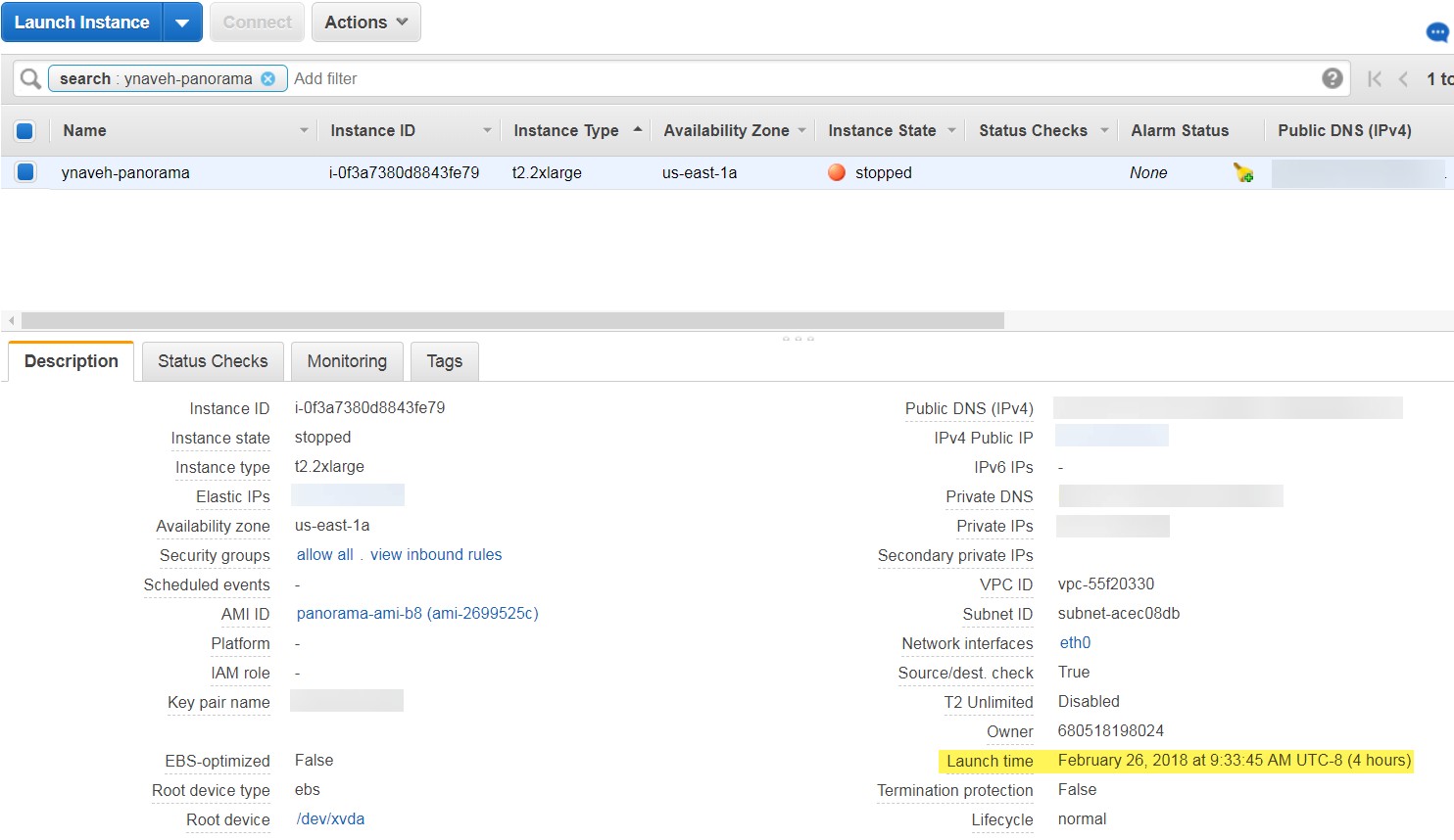
| STEP 4 | |
Shut down the Panorama virtual appliance.
|
|---|---|
| STEP 5 | | Create or assign an Elastic IP (EIP) address to the management interface. |
-
Select Services > EC2 > Elastic IPs and Allocate Elastic IP address .
-
Select a Network Border Group to specify the logical group of zones from where the public IP4v address is advertised.
-
For the Public IPv4 address pool, select Amazon’s pool of IPv4 addresses .
-
Allocate the EIP.
-
Click the IPv4 address in the Allocated IPv4 address column and Associate Elastic IP address .
-
Select the Panorama virtual appliance Instance.
-
Select the Panorama virtual appliance Private IP address to with which to associate the EIP.
STEP 6 | Power on the Panorama virtual appliance.
-
On the EC2 Dashboard, select Instance .
-
From the list, select the Panorama virtual appliance and click Actions > Instance State > Start .
STEP 7 | Configure a new administrative password for the Panorama virtual appliance.
You must configure a unique administrative password before you can access the web interface of the Panorama virtual appliance. To access the CLI, the private key used to launch the Panorama virtual appliance is required.
The new password must be a minimum of eight characters and include a minimum of one lowercase character, one uppercase character, and one number or special character.
• If you have an SSH service installed on your computer:
-
Enter the following command to log into the Panorama virtual appliance:
ssh -i <private_key.ppk> admin@<public-ip_address>
-
Configure a new password using the following commands and follow the on screen prompts:
admin> configure
admin# set mgt-config users admin password
-
If you need to activate a BYOL, set the DNS server IP address so that the Panorama virtual appliance can access the Palo Alto Networks licensing server. Enter the following command to set the DNS server IP address:
admin# set deviceconfig system dns-setting servers primary <ip_address>
-
Commit your changes with the command:
admin# commit
-
Terminate the SSH session.
• If you are using PuTTY to SSH into the Panorama virtual appliance:
-
If you are using an existing key pair and have the .ppk file available, continue to the Step 7.3. If you created a new key pair or have only the .pem file of the existing key pair, open PuTTYgen and Load the .pem file.
-
Save the private key to a local accessible destination.
-
Open PuTTY and select SSH > Auth and then Browse to the .ppk file you saved in the previous step.
-
Select Sessions and enter the public IP address of the Panorama virtual appliance. Click Open and click Yes when the security prompt appears.
-
Log in as admin when prompted.
-
Configure a new password using the following commands and follow the onscreen prompts:
admin> configure
admin# set mgt-config users admin password
-
Set the DNS server IP address so that the Panorama virtual appliance can access the Palo Alto Networks licensing server. Enter the following command to set the DNS server IP address:
admin# set deviceconfig system dns-setting servers primary <ip_address>
-
Commit your changes with the command:
admin# commit
-
Terminate the SSH session.
STEP 8 | Register the Panorama virtual appliance and activate the device management license and support licenses.
-
(VM Flex Licensing Only) Provisioning the Panorama Virtual Appliance Serial Number .
When leveraging VM Flex licensing, this step is required to generate the Panorama virtual appliance serial number needed to register the Panorama virtual appliance with the Palo Alto Networks Customer Support Portal (CSP).
-
Register Panorama.
You must register the Panorama virtual appliance using the serial number provided by Palo Alto Networks in the order fulfillment email.
This step is not required when leveraging VM Flex licensing as the serial number is automatically registered with the CSP when generated.
-
Activate the firewall management license.
-
Activate/Retrieve a Firewall Management License when the Panorama Virtual Appliance is Internet-connected.
-
Activate/Retrieve a Firewall Management License when the Panorama Virtual Appliance is not Internet-connected.
-
4. Activate a Panorama Support License.
STEP 9 | Complete configuring the Panorama virtual appliance for your deployment needs.
-
For Panorama in Log Collector Mode.
-
Add a Virtual Disk to Panorama on AWS as needed.
-
Adding at least one virtual logging disk is required before you can change the Panorama virtual appliance to Log Collector mode.
-
Begin at Step 6 to switch to Log Collector mode.
-
For Panorama in Panorama mode.
-
Add a Virtual Disk to Panorama on AWS.
-
Adding at least one virtual logging disk is required before you can change the Panorama virtual appliance to Panorama mode.
-
Set up a Panorama Virtual Appliance in Panorama Mode.
-
Configure a Managed Collector.
-
For Panorama in Management Only mode.
-
Set up a Panorama Virtual Appliance in Management Only Mode.
-
Configure a Managed Collector to add a Dedicated Log Collector to the Panorama virtual appliance.
-
Management Only mode does not support local log collection, and requires a Dedicated Log Collector to store managed device logs.
Install Panorama on AWS GovCloud
You can now deploy Panorama ™ and a Dedicated Log Collector on Amazon Web Services (AWS) GovCloud . AWS GovCloud is an isolated AWS region that meets the regulatory and compliance requirements of the US government agencies and customers. Panorama deployed on AWS GovCloud is Bring Your Own License (BYOL), supports all deployment modes (Panorama, Log Collector, and Management Only). For more information on Panorama modes, see Panorama Models.
To secure your workloads that contain all categories of Controlled Unclassified Information (CUI) data and government-oriented, publicly available data in the AWS GovCloud (US) region, the Panorama virtual appliance provides the same security features offered in the standard AWS public cloud on AWS GovCloud. The Panorama virtual appliance on AWS GovCloud and the standard AWS public cloud support the same features and capabilities.
Review the Setup Prerequisites for the Panorama Virtual Appliance to review the supported EC2 instance types. Once you are ready, refer to Install Panorama on AWS to install the Panorama virtual appliance on AWS GovCloud.
See the following procedures to add additional logging storage to your Panorama virtual appliance, or to increase the allocated CPU cores and memory:
-
Add a Virtual Disk to Panorama on AWS
-
Increase CPUs and Memory for Panorama on AWS
Install Panorama on Azure
You can now deploy Panorama™ and a Dedicated Log Collector on Microsoft Azure. Panorama deployed on Azure is Bring Your Own License (BYOL), supports all deployment modes (Panorama, Log Collector, and Management Only), and shares the same processes and functionality as the MSeries hardware appliances. For more information on Panorama modes, see Panorama Models.
STEP 1 | Log into to the Microsoft Azure portal .
STEP 2 | Set up the virtual network for your network needs.
Whether you launch the Panorama virtual appliance in an existing virtual network or you create a new virtual network, the Panorama virtual appliance must be able to receive traffic from other instances in the virtual network and perform inbound and outbound communication between the virtual network and the internet as needed.
Refer to the Microsft Azure Virtual Network documentation for more information.
-
Create a Virtual Network or use an existing virtual network.
-
Verify that the network and security components are appropriately defined.
-
Create a NAT gateway if you want to enable only outbound internet access for the subnet to which the Panorama virtual appliance belongs.
-
Create subnets. Subnets are segments of the IP address range assigned to the VNet in which you can launch Microsoft Azure instances. It is recommended that the Panorama virtual appliance belong to the management subnet so that you can configure it to access the internet if needed.
-
Add routes to the route table for a private subnet to ensure traffic can be routed across subnets in the VNet and from the internet if applicable.
-
Ensure you create routes between subnets to allow communication between:
-
Panorama, managed firewalls, and Log Collectors.
-
(Optional) Panorama and the internet.
-
Ensure that the following ingress security rules are allowed for the VNet to manage VNet traffic. The ingress traffic source for each rule is unique to your deployment topology.
See Ports Used for Panorama for more information.
-
Allow SSH (port 22 ) traffic to enable access to the Panorama CLI.
-
Allow HTTPS (port 443 ) traffic to enable access to the Panorama web interface.
-
Allow traffic on port 3978 to enable communication between Panorama, manage firewalls, and managed Log Collectors. This port is also used by Log Collectors to forward logs to Panorama.
-
Allow traffic on port 28443 to enable managed firewalls to get software and content updates from Panorama.
STEP 3 | Deploy the Panorama virtual appliance.
-
In the Azure Dashboard, select Virtual machines and Add a new virtual machine.
-
Search for Palo Alto Networks and select the latest Panorama virtual appliance image.
-
Create the Panorama virtual appliance.
STEP 4 | Configure the Panorama virtual appliance.
-
Select your Azure Subscription .
-
Select the Azure Resource Group to contain all your Azure instance resources.
-
Enter a Virtual machine name for the Panorama virtual appliance.
-
Select the Region for the Panorama virtual appliance to be deployed in.
-
(Optional) Select the Availability options . See How to use availability sets for more information.
-
Select the Image used to deploy the Panorama management server. Browse all public and private images to deploy the Panorama management server from the Panorama image on the Azure marketplace.
-
Configure the Panorama virtual appliance size. Review the Setup Prerequisites for the Panorama Virtual Appliance for sizing requirements.
-
Configure the unique Panorama virtual appliance administrator credentials.
You must configure a unique administrative password before you can access the web interface and CLI of the Panorama virtual appliance.
-
Enter a Username for the Panorama virtual appliance administrator. To ensure that your username is secure, admin is not a valid entry.
-
Enter a Password or copy and paste an SSH public key for securing administrative access to the Panorama virtual appliance.
-
Configure the Panorama virtual appliance instance Networking
-
Select an existing Virtual network or create a new virtual network.
-
Configure the Subnet . The subnet is dependent on the virtual network you selected or created in the previous step. If you selected an existing virtual network, you can choose one of the subnets for the selected virtual network.
-
Select an existing Public IP address or create a new one. This creates the management interface used to access your Panorama virtual appliance.
-
Select an existing NIC network security group or create a new security group . Network security groups control traffic to the virtual machine. Make sure that HTTPS and SSH are allowed for the Inbound rules.
-
-
Configure the instance Management settings.
-
Select whether to enable Auto-shutdown . Auto-shutdown allows you to configure a daily time to automatically shut down the virtual machine that you disable autoshutdown to avoid the possibility that a new public IP address gets assigned to the virtual machine, that logs are dropped, that logs are not or that you are unable to manage your firewalls while the Panorama virtual appliance is shut down.
-
Select whether to enable boot Monitoring . Select the Diagnostic storage account if enabled. Monitoring automatically sends boot-up diagnostic logs to your Diagnostics storage account. For more information, see Overview of Monitoring in Microsoft Azure.
-
Configure any other settings as needed.
-
-
Review the summary, accept the terms of use and privacy policy, and Create the Panorama virtual appliance.
STEP 5 | Verify that you the Panorama virtual appliance has been successfully deployed.
-
Select Dashboard > Resource Groups and select the resource group containing the Panorama virtual appliance.
-
Under Settings, select Deployments for the virtual machine deployment status.
|
|
|---|---|
| STEP 6 | |
Configure a static Public IP address.
|
| STEP 7 | | Log in to the web interface of the Panorama virtual appliance. |
-
On the Azure portal, in All Resources , select the Panorama virtual appliance and view the public IP address located in the Overview section.
-
Use a secure (https) connection from your web browser to log in to the Panorama virtual appliance using the public IP address.
-
Enter the username and password of the Panorama virtual appliance. You are prompted with a certificate warning. Accept the certificate warning and continue to the web page.
STEP 8 | Register the Panorama virtual appliance and activate the device management license and support licenses.
-
(VM Flex Licensing Only) Provisioning the Panorama Virtual Appliance Serial Number .
When leveraging VM Flex licensing, this step is required to generate the Panorama virtual appliance serial number needed to register the Panorama virtual appliance with the Palo Alto Networks Customer Support Portal (CSP).
-
Register Panorama.
You must register the Panorama virtual appliance using the serial number provided by Palo Alto Networks in the order fulfillment email.
This step is not required when leveraging VM Flex licensing as the serial number is automatically registered with the CSP when generated.
-
Activate the firewall management license.
-
Activate/Retrieve a Firewall Management License when the Panorama Virtual Appliance is Internet-connected.
-
Activate/Retrieve a Firewall Management License when the Panorama Virtual Appliance is not Internet-connected.
-
-
Activate a Panorama Support License.
STEP 9 | Complete configuring the Panorama virtual appliance for your deployment needs.
-
For Panorama in Log Collector Mode.
-
Add a Virtual Disk to Panorama on Azure as needed.
-
Adding at least one virtual logging disk is required before you can change the Panorama virtual appliance to Log Collector mode.
-
Begin at Step 6 to switch to Log Collector mode.
-
For Panorama in Panorama mode.
-
Add a Virtual Disk to Panorama on Azure.
-
Adding at least one virtual logging disk is required before you can change the Panorama virtual appliance to Panorama mode.
-
Set up a Panorama Virtual Appliance in Panorama Mode.
-
Configure a Managed Collector.
-
For Panorama in Management Only mode.
-
Set up a Panorama Virtual Appliance in Management Only Mode.
-
Configure a Managed Collector to add a Dedicated Log Collector to the Panorama virtual appliance.
-
Management Only mode does not support local log collection, and requires a Dedicated Log Collector to store managed device logs.
Install Panorama on Google Cloud Platform
You can now deploy Panorama™ and a Dedicated Log Collector on Google Cloud Platform (GCP). Panorama deployed on GCP is Bring Your Own License (BYOL), supports all deployment modes (Panorama, Log Collector, and Management Only), and shares the same processes and functionality as the M-Series hardware appliances. For more information on Panorama modes, see Panorama Models.
To deploy the Panorama virtual appliance on GCP, you need to build a custom image. To begin this process, you must download the Panorama tar.gz from the Palo Alto Networks Customer Support portal and upload it to a GCP storage bucket. You can then create the custom image and use the image to deploy the Panorama virtual appliance on GCP.
STEP 1 | Download the Panorama virtual appliance image.
-
Log in to the Palo Alto Networks Support Portal.
-
Select Updates > Software Updates and filter by Panorama Base Images .
-
Download the latest version of the Panorama on GCP tar.gz image.
STEP 2 | Upload the Panorama virtual appliance image to the Google Cloud Platform.
-
Log in to the Google Cloud Console .
-
From the Products and Services menu, select Storage .
-
Click Create Bucket , configure the new storage bucket and click Create.
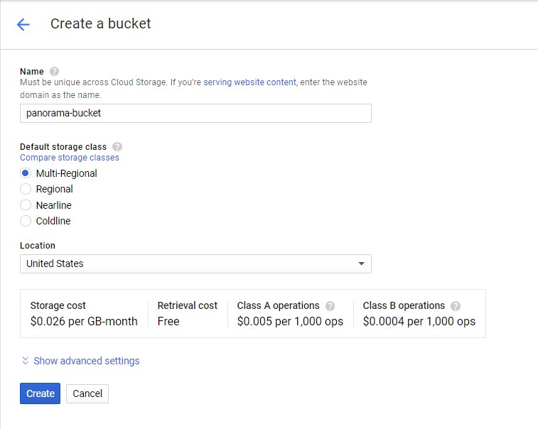
-
Select the storage bucket you created in the previous step, click Upload files , and select the Panorama virtual appliance image you downloaded.
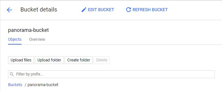
-
From the Products and Services menu, select Compute Engine > Images .
-
Click Create Image and create the Panorama virtual appliance image:
-
Name the Panorama virtual appliance image.
-
In the Source field, select Cloud Storage file from the drop-down menu.
-
Click Browse and navigate to the storage bucket where you uploaded the Panorama virtual appliance image, and Select the uploaded image.
-
-