Configuring a Point-to-Point GRE Tunnel
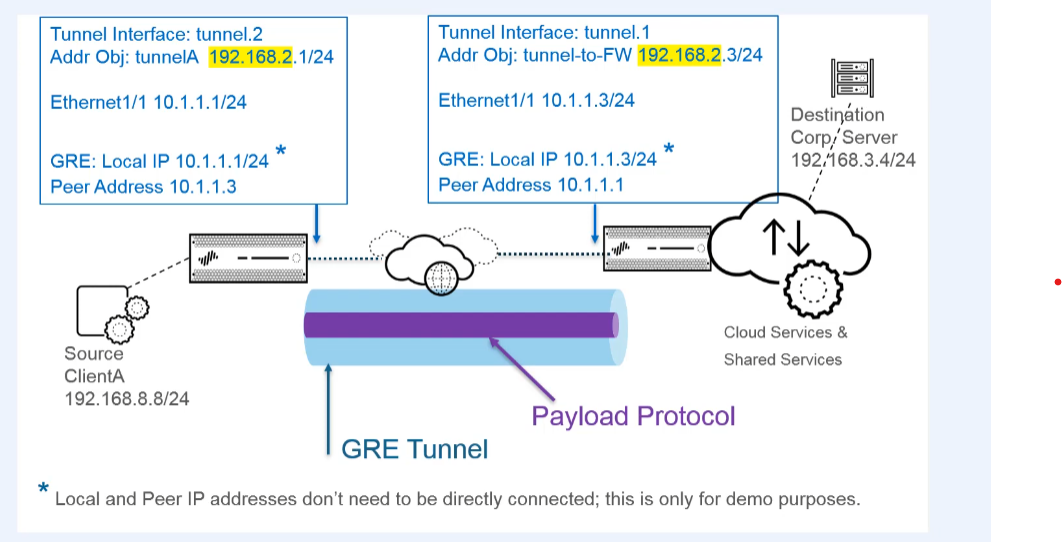
Hello, today we're creating a point-to-point GRE tunnel to direct packets from the firewall to a cloud service while they're on their way to a particular end destination. Here's a diagram of our topology. We're directing packets to the cloud service, for example, because the cloud service implements URL filtering on them.
Our firewall interface is one tunnel endpoint, and a router or another firewall in the cloud service is the other tunnel endpoint.
Firewall 1 (Local Side) Configuration
1. Create a Tunnel Interface
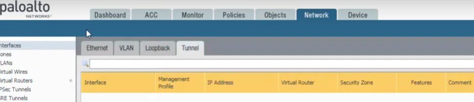
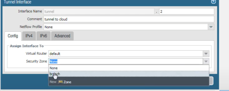
Create a tunnel interface by selecting
Network > Interfaces > Tunnel
and clicking
Add
to add a new interface. The name is
tunnel
.
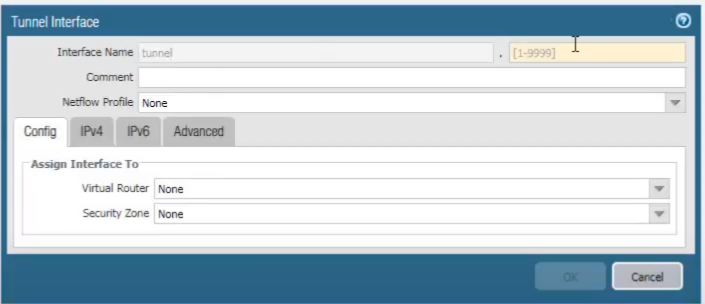
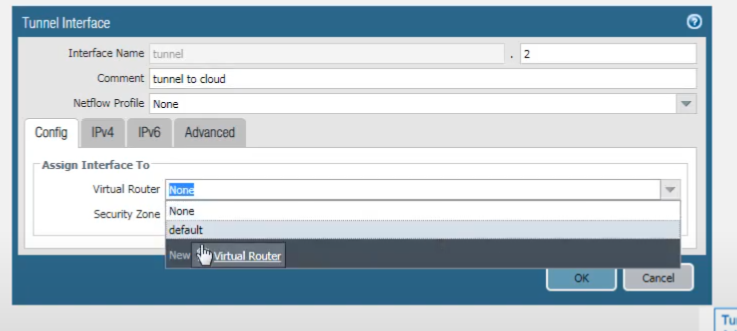
After the dot, we enter the number of the tunnel (e.g.,
tunnel.1
). We add a comment and assign the tunnel interface to a virtual router (e.g.,
default
).
We assign it to a Layer 3 security zone (e.g., creating a new zone named
GRE_Zone
or using an existing one like
Trust
or
VPN
).
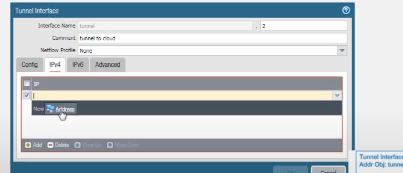
We can add an IPv4 or IPv6 address to the tunnel interface, or both. We'll select IPv4.
And add a new address object. We'll name it
Tunnel-1-IP
.
Select
IP Netmask
and enter the address
192.168.2.1/24
.
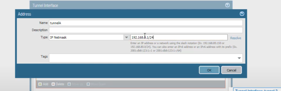
The tunnel interface addresses at each end of the tunnel should be on the same subnet, which in this case is
192.168.2.0/24
.
2. Configure Physical Interface (GRE Endpoint Source)
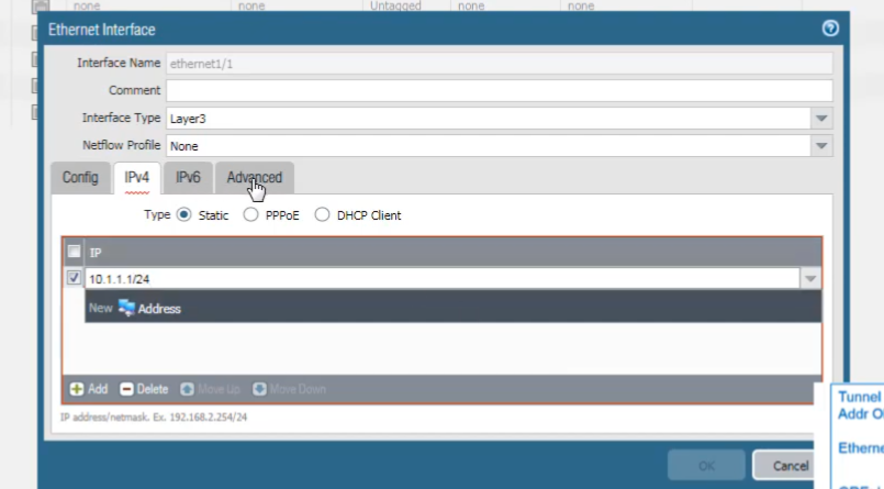
We assign an IP address to our Ethernet interface that will serve as the source for the GRE tunnel. Select
Network > Interfaces > Ethernet
, select an interface (e.g.,
ethernet1/1
). It must be of type Layer 3. Select the same virtual router used before (e.g.,
default
). Select a security zone (e.g.,
Untrust
if it's an external-facing interface).
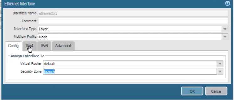
We will assign the address. Choose the IPv4 tab.
And click
Add
to assign an IP address, for example,
10.1.1.1/24
.
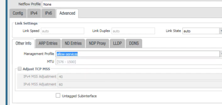
On the Advanced tab, select or create a management profile to allow services such as pings if needed for testing the physical interface.
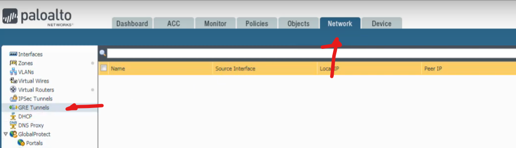
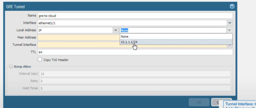
3. Create the GRE Tunnel Object
Now we create the GRE tunnel. Select Network > GRE Tunnels .
And click
Add
. For the tunnel name, we'll call it
GRE-to-Cloud
. Select the interface to use as the local GRE tunnel endpoint; this is the source interface. We select
ethernet1/1
, which we configured. For the
Local IP Address
, choose the IP address of the interface you just selected (
10.1.1.1
). The interface could have more than one IP address.
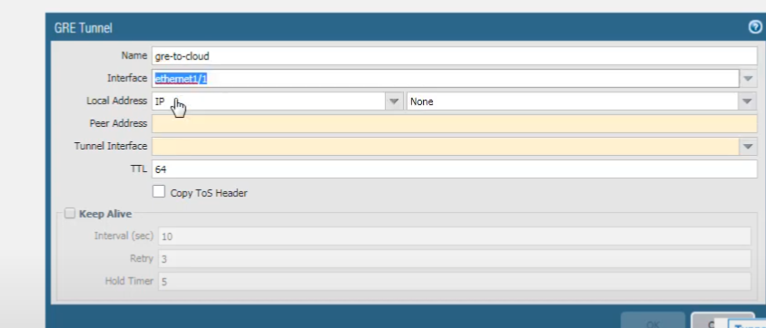
There's our address.
For the
Peer Address
, we'll add
10.1.1.3
(the public IP of the peer GRE endpoint). For the
Tunnel Interface
, select the tunnel interface you first created (
tunnel.1
).
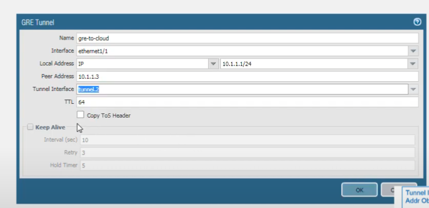
Note that the local and the peer IP addresses (
10.1.1.1
and
10.1.1.3
) don't need to be directly connected if there's routing between them; this configuration assumes they are reachable over the transport network. Accept the default TTL value of 64; that's the TTL of the IP packet encapsulating the GRE packet. If your network uses QoS and depends on Type of Service bits to enforce QoS policies, select
Copy TOS Header
to copy the TOS field from the inner IP header to the outer IP header in the encapsulated packets. This preserves the original TOS information.
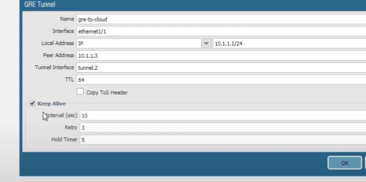
Next, we enable the Keep Alive function for the tunnel. It's a best practice so that if the tunnel goes down, the firewall removes the routes associated with the tunnel from its forwarding table and can then use your backup route.
4. Configure Static Route for GRE Traffic
We must now route the traffic that we want going to the cloud service (and ultimately to the destination server) through the GRE tunnel. Select
Network > Virtual Routers
, select our
default
virtual router, and go to
Static Routes
.
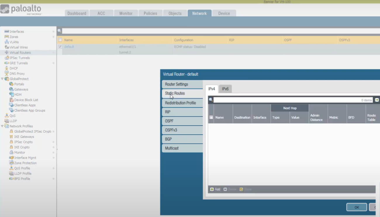
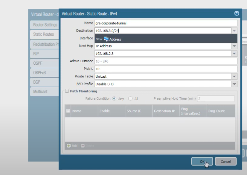
We're going to add an IPv4 static route. Name it (e.g.,
Route-To-Remote-Net-Via-GRE
). The
Interface
is the outgoing interface for our GRE tunnel, which is
tunnel.1
. The
Next Hop
is the IP address of the peer's GRE tunnel interface; enter
192.168.2.3
. The
Destination
is the network of the destination server (e.g.,
192.168.1.0/24
if that's the remote network we want to reach). Click OK.
Note: The original document screenshot shows a destination of 192.168.3.0/24 for this route, which might be for "Client A's network" if the traffic flow was reversed in that example, or if the server was in 192.168.3.0/24. For this guide, we assume the target server network is 192.168.1.0/24 as per the initial clarification of "network on the other side". Adjust the destination according to your actual topology.
Click OK.
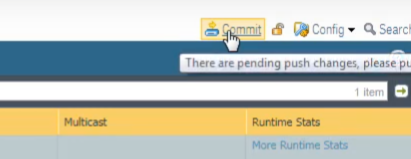
And commit the changes.
Firewall 2 (Peer/Cloud Service Side) Configuration
Now we're going to configure the device at the other end of the tunnel. Here we are logged into the firewall at the other end of the tunnel.
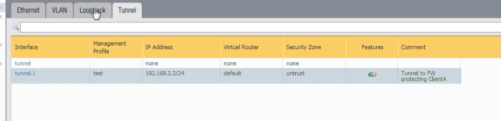
Its
tunnel.1
interface IP address is
192.168.2.3/24
.
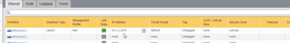
For our Ethernet interface, we have
ethernet1/1
with the IP address
10.1.1.3/24
.
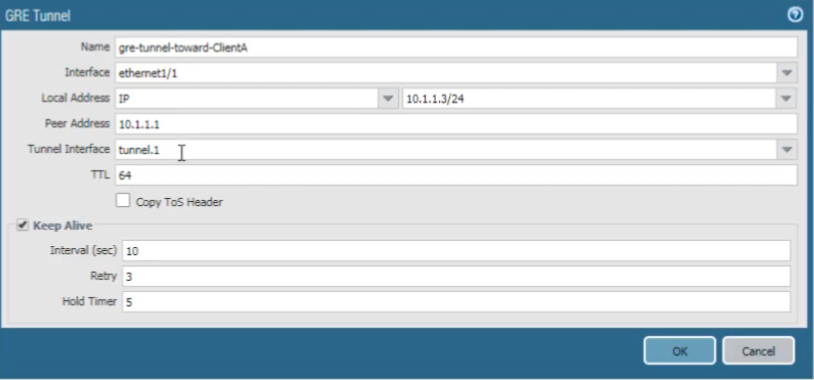
For our GRE tunnel configuration on this peer firewall, the local tunnel endpoint source is its
ethernet1/1
interface IP address (
10.1.1.3/24
). The
Peer Address
(Firewall 1's public IP) is
10.1.1.1
. The
Tunnel Interface
is the one we just configured on this peer firewall,
tunnel.1
.
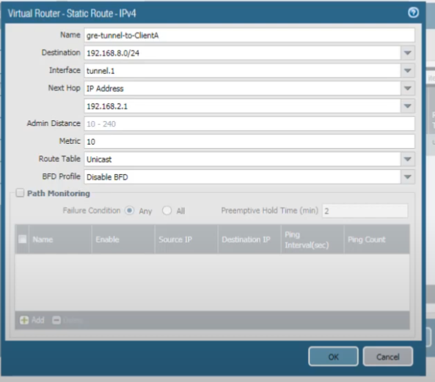
Finally, we created a static route. This route is for traffic destined to the network of Client A (e.g.,
192.168.3.0/24
, assuming Client A is in that network). We want that traffic to take
tunnel.1
, and the
Next Hop
for this route is the IP address of Firewall 1's GRE tunnel interface, which is
192.168.2.1
.
Testing the GRE Tunnel
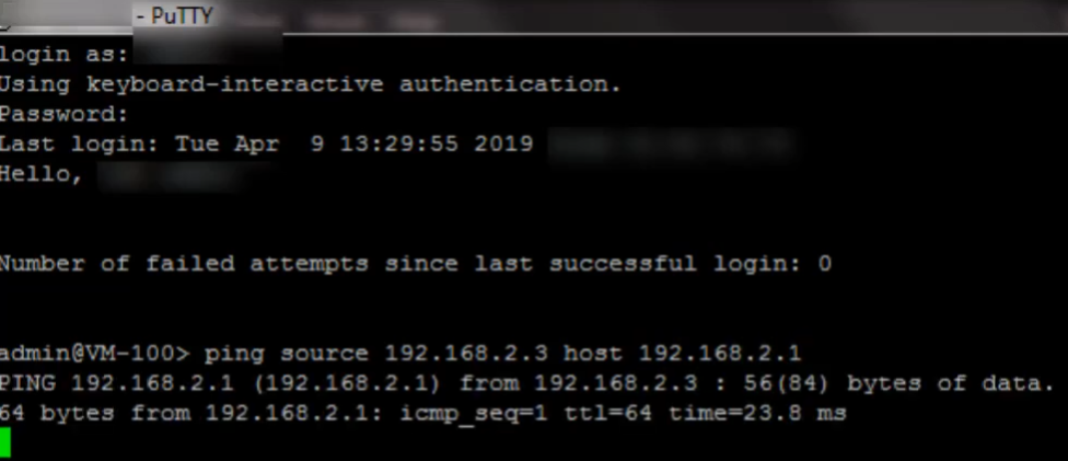
Now we ping the peer GRE tunnel interface IP address to test the GRE tunnel. Here we are logged into the second firewall (Firewall 2). We ping
192.168.2.1
(Firewall 1's tunnel.1 IP), and we see that the pings are successful. They are going over the GRE tunnel.
Remember to also configure appropriate security policies on both firewalls to allow the GRE protocol (IP Protocol 47) between the public GRE endpoints, and also to allow the actual data traffic (e.g., ICMP, TCP, UDP applications) to flow through the tunnel interfaces between the respective security zones.