🔗 OSPF Virtual Links in Palo Alto Networks
1. Overview and Purpose
A fundamental rule in OSPF is that all non-backbone areas must maintain connectivity to the backbone area (Area 0) . This ensures that inter-area routing information (Type 3 LSAs) can be properly distributed throughout the OSPF domain via Area 0. However, physical topology constraints or network design choices might result in an area becoming disconnected from Area 0.
An OSPF Virtual Link is a logical connection configured between two Area Border Routers (ABRs) that share a common non-backbone area (the "transit area"). This virtual link acts as a point-to-point connection through the transit area, effectively extending Area 0 to the ABR of the disconnected area.
The primary purposes of a virtual link are:
- Connecting a Disconnected Area to the Backbone: To provide a logical path to Area 0 for an area that lacks a direct physical connection.
- Connecting a Partitioned Backbone Area: To logically stitch together two parts of a physically partitioned Area 0 using a non-backbone area as transit (though this is generally discouraged in favor of redesigning Area 0).
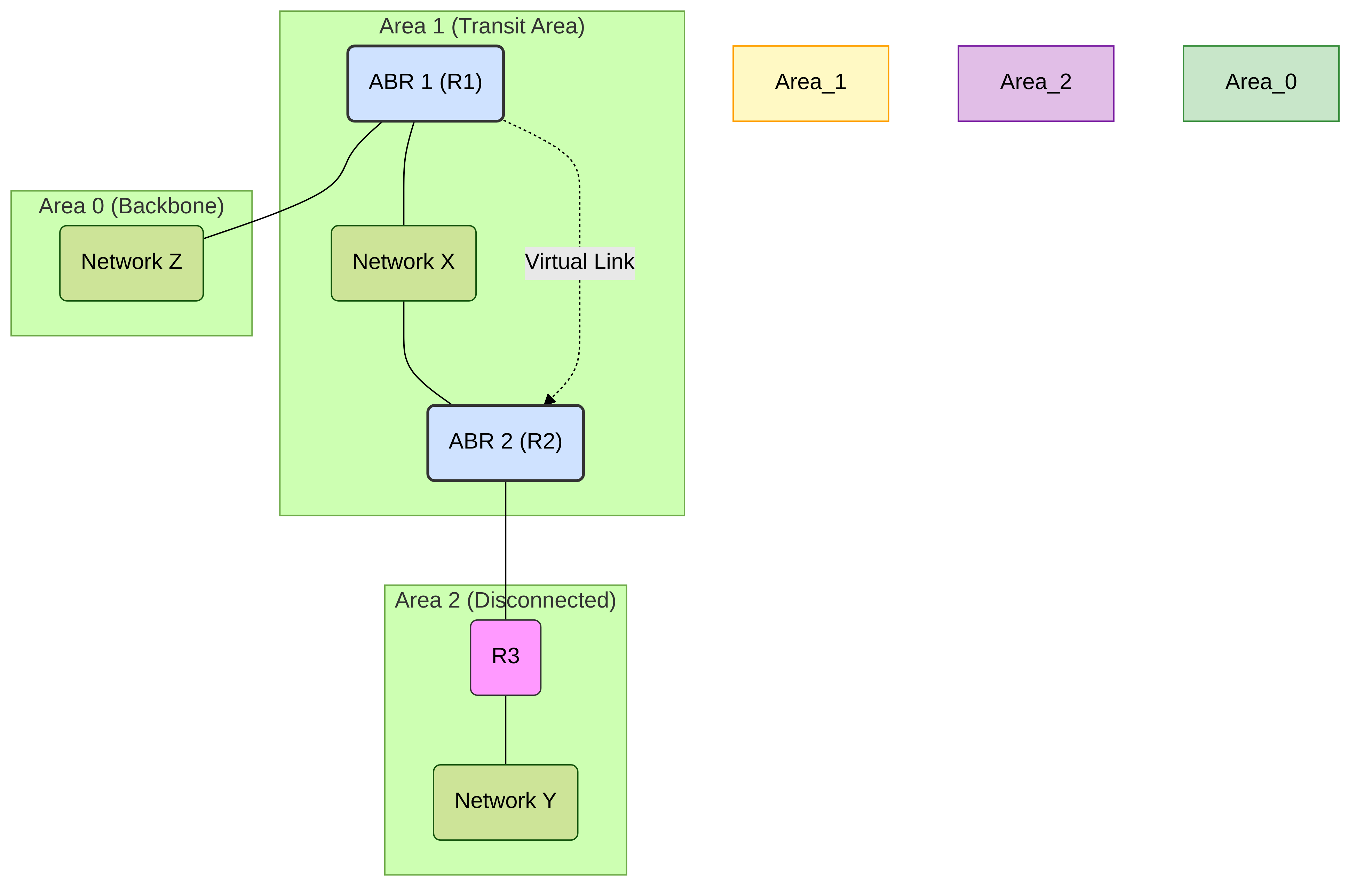
Diagram: OSPF Virtual Link connecting Area 2 to Area 0 via Transit Area 1
2. Configuring OSPF Virtual Links in PAN-OS
To configure a virtual link on a Palo Alto Networks firewall (which must be acting as an ABR involved in the virtual link):
-
Navigate to
Network > Virtual Routersand select the virtual router where OSPF is configured. -
Go to the
OSPFtab, then theAreassub-tab. - Select the OSPF area that will serve as the Transit Area for the virtual link (the area that both ABRs share and through which the link will pass). Click on its name to edit it.
- Inside the Area configuration window, click on the Virtual Link tab.
- Click Add to create a new virtual link entry.
-
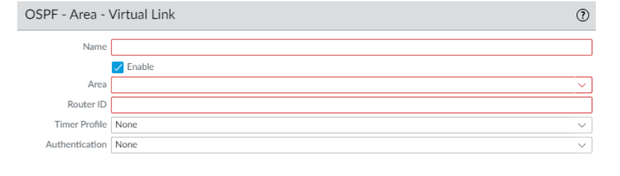
Configure the following parameters:
-
Name:
Provide a descriptive name for this virtual link configuration entry (e.g.,
VL_to_ABR2_via_Area1). This name is locally significant. - Enable: Check this box to activate the virtual link.
- Neighbor ID: Enter the Router ID of the *other* ABR that forms the remote endpoint of this virtual link.
- Transit Area: This field will be pre-populated with the Area ID you selected in step 3. Verify it's the correct common transit area.
- Hello Interval / Dead Interval / Retransmit Interval / Transit Delay: (Optional) Adjust OSPF timers specifically for the virtual link interface if needed. Generally, defaults are sufficient unless specific network conditions require tuning.
- Authentication Profile: (Optional) If OSPF authentication is enabled within the transit area or specifically for the virtual link, select the appropriate Authentication Profile containing the shared key or settings. Both ends must match.
-
Name:
Provide a descriptive name for this virtual link configuration entry (e.g.,
- Click OK to save the virtual link configuration within the transit area settings.
- Click OK again to close the Area configuration window.
- Repeat Configuration: Remember that the virtual link configuration must be mirrored on the other ABR at the opposite end of the virtual link, specifying the first ABR's Router ID as the Neighbor ID.
- Commit the changes.
For detailed steps and context, refer to the official Palo Alto Networks documentation: Configure OSPF – Palo Alto Networks (Link is for 10.1, adjust version as needed).
3. Important Considerations & Requirements
- ABR Requirement: Both routers forming the endpoints of the virtual link must be Area Border Routers (ABRs) .
- Transit Area Connectivity: The Transit Area itself must be fully connected to Area 0 (it cannot be a stub or NSSA area) and cannot be partitioned. The virtual link relies on intra-area routing within the transit area to establish the logical connection between the ABRs.
- Shared Transit Area: Both ABRs involved must share the common transit area specified in the configuration.
- Router ID Uniqueness: Each router in the OSPF domain, especially the ABRs involved, must have a unique OSPF Router ID.
- Authentication Consistency: If OSPF authentication is used, the authentication type and keys/passwords configured for the virtual link must match exactly on both ABRs.
- Cost: The cost of the virtual link is the intra-area path cost through the transit area between the two ABRs.
- Not a Replacement for Good Design: Virtual links add complexity and are often considered a workaround for suboptimal network designs. Whenever possible, directly connecting areas to the backbone is preferred. Avoid chaining multiple virtual links.
4. Monitoring and Troubleshooting Virtual Links
Once configured, you need to verify that the virtual link comes up and is stable.
4.1. CLI Commands
-
Verify Virtual Link State:
The primary command is:
show routing protocol ospf virtual-linkLook for the
Statefield, which should beP2P(Point-to-Point) indicating the virtual link adjacency is up. Other states (like Down, Point-to-Point) indicate potential issues. It also shows neighbor ID, cost, and timers. -
Check OSPF Neighbors:
The virtual link should appear as an OSPF neighbor.
show routing protocol ospf neighborLook for the neighbor Router ID configured for the virtual link. The interface should be listed as something like
vlink(Area.Neighbor ) -
Examine OSPF Interface:
The virtual link acts as a logical interface.
show routing protocol ospf interfaceFind the entry corresponding to the virtual link to check its state, cost, and timers.
-
Check LSDB for Reachability:
Ensure the ABRs have routes to each other within the transit area. Check Type 1 LSAs within the transit area.
show routing protocol ospf lsdb area
type router
4.2. GUI Monitoring
-
Runtime Stats:
Navigate to
Network > Virtual Routers > (select VR) > More Runtime Stats > OSPF.- Interface Tab: Look for the virtual link interface entry and check its state.
- Neighbor Tab: Verify the neighbor relationship over the virtual link.
4.3. Common Issues
- Mismatched Configuration: Ensure Neighbor ID, Transit Area ID, and Authentication settings match on both ABRs.
- Transit Area Issues: The transit area itself must be stable, connected to Area 0, and provide a path between the ABRs. Issues within the transit area (e.g., area partitioning, interface down) will break the virtual link.
- Router ID Conflicts: Duplicate Router IDs can prevent adjacency formation.
- Authentication Failures: Mismatched keys or authentication types.
- Firewall Policies: Although OSPF traffic over the virtual link is encapsulated within IP packets routed through the transit area, ensure underlying network connectivity and any relevant security policies between the ABRs (over the transit area path) allow OSPF protocol traffic if filtering is strict.